An Implementation of the Deutsch-Jozsa Algorithm on Molecular Vibronic Coherences Through Four-Wave Mixing: a Theoretical Study
Abstract
Time-Frequency Resolved Coherent Anti-Stokes Raman Scattering (TFRCARS) was recently proposed as a means to implement quantum logic using the molecular ro-vibrational manifold as a quantum register [R. Zadoyan et al., Chem. Phys. 266, (2001) 323]. We give a concrete example of how this can be accomplished through an illustrative algorithm that solves the Deutsch-Jozsa problem. We use realistic molecular parameters to recognize that, as the problem size expands, shaped pulses must be tailored to maintain fidelity of the algorithm.
keywords:
Four-wave mixing , coherent spectroscopy , quantum computingPACS:
03.67.Lx , 82.53.Kp1 Introduction
Logic operations for quantum computation (QC) between two or more quantum bits (qubits) have so far been experimentally demonstrated in liquid-state NMR [1], trapped ions [2], and cavity quantum electrodynamics [3]. Recently, Time-Frequency Resolved Coherent Anti-Stokes Raman Scattering (TFRCARS) in the molecular ro-vibronic Hilbert space, was proposed as an alternative approach [4]. Through measurements on room temperature iodine vapor, it was demonstrated that the elements sufficient for executing universal quantum logic, namely, the single qubit rotations and the two-qubit controlled-not gate, are naturally contained in TFRCARS. Here, we give an illustrative example of how such elements can be combined into a useful algorithm. We show how a TFRCARS interference experiment can use the molecular vibrational level structure to solve the Deutsch-Jozsa (DJ) problem [5]. The DJ problem has become a benchmark for demonstrations of algorithms on prototypes of quantum computers; having so far been used in NMR [6, 7, 8, 9, 10, 11], linear optics [12], ro-vibrational molecular wavepackets in a pump-probe experiment [13], and excitons in semiconductor quantum dots [14].
TFRCARS is a four-wave mixing experiment in which a sequence of three non-collinear, short laser pulses (labeled P, S and P’) are used to resonantly prepare and manipulate molecular ro-vibronic coherences. The P-pulse acts on a statistical state to prepare the first-order polarization where represents the rotational, vibrational and electronic quantum indices . The S and P’ pulses then allow manipulation of the coherence through stimulated transitions to sequentially prepare second- and third-order coherences, consisting of complex superpositions determined by the radiation field. Transform-limited interrogation of the evolving third-order coherence can then be accomplished through the projective measurement of gated detection of the spectrally dispersed third-order polarization, [4, 15, 16]. Energy and momentum conservation conditions, enforced through spectral and spatial filtering of , allow its detection without any interference from the incoherent background. The process can be mapped out as logic operations on the molecular register of eigenstates, by identifying the P pulse as initialize, S and P’ pulses as process, and the gate pulse as readout. The approach has several attractive features with regard to QC. Since transitions involve electronic resonances, they can be carried out on fs time scales. A very large ratio of coherence to process time is afforded, even when we allow for decoherence to be determined by the non-fundamental limit of inhomogeneous translational distribution (doppler broadening) at room temperature. Unlike NMR, which aims to manipulate effective pure states, in TFRCARS the signal is only from the polarized sub-ensemble [4]. Very large superpositions, ro-vibrational eigenstates, can be manipulated with precision. Finally, since the signal consists of a coherent radiation beam, information can be transferred effectively and can be used to cascade operations. Small scale CARS-QC experiments, using several qubits, are currently being set up at Irvine. The limited number of qubits and process steps in the presently conceived algorithms, suggest applications in quantum communication [17], and simple quantum information processing tasks, such as quantum privacy amplification and cryptography [18]. Even the simplest of propositions in quantum control of molecules [19] must contend with complications inherent in molecular state structures, such as vibrational level structures imposed by anharmonicity of electronic potential energy surfaces. As such, principles of optimal control [20] will invariably be required in devising pulse shapes tailored for various implementations [21, 22]. We highlight these considerations, by using realistic molecular parameters, intuitively obvious pulse shapes, and a clear computational task of solving the DJ problem. Finally, we note that in the short time after suggesting the mapping of 4-wave mixing onto QC [4], there have been demonstrations of the general approach by other groups as well [23, 24].
2 Deutsch-Jozsa algorithm
The DJ algorithm is one of the first examples of a quantum algorithm exhibiting a speedup compared to classical computers. The algorithm solves the following problem: “There is a finite set where is even, and an unspecified function that is promised to be either constant [ or ] or balanced [ on exactly half the inputs]. Decide with certainty whether is constant or balanced in the least number of evaluations of .” The DJ algorithm has been extensively analyzed [25]. We now describe an alternative algorithm for solving the DJ problem, one that is optimized for an interference experiment. Let be an -dimensional Hilbert-space, where . Define a basis in in one-to-one correspondence with the elements : .
-
1.
Prepare the equal coherent superposition .
-
2.
Define an operator by its action on the basis elements as: . Then: .
-
3.
Make a projective measurement on .
The output (the signal) becomes:
| (1) |
Since is either or , the terms in the sum are or , respectively. It is clear that for balanced, the sum contains an equal number of positive and negative terms. The signal in this case is zero. For constant , all the terms have the same sign, so the absolute value of the signal becomes maximal. The signal therefore distinguishes the two types of functions and hence this modified algorithm performs the same task as the standard algorithm [25]. Furthermore, it too does so using just one -evaluation.111Our algorithm is similar to one described in [26], except that it does not use a qubit tensor-product structure.
3 Scheme of proposed experiment
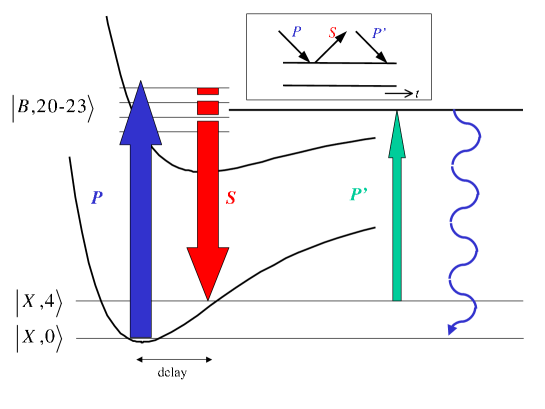
We now propose a concrete experiment on iodine (I2) vapor to perform our alternative DJ algorithm. We illustrate the proposal through numerical simulations using accurately known molecular parameters. Vibrational levels represent the basis states of . Fig. 1 shows the iodine potentials for the ground () and excited () electronic states. We choose pulse widths and processing times 1 ps, on which time scale the evolution of molecular rotations can be ignored, and therefore, we need only to be concerned with the vibrational levels on each potential. The CARS process is illustrated in Fig. 1 through the relevant time-circuit diagram (Feynman diagram in inset).
Initially the molecule is in its ground electronic state , where the first (second) index denotes electronic (vibrational) quantum numbers.
The P (pump) pulse induces the transition . A short enough P-pulse is chosen to prepare the desired number of -states with comparable amplitude. This step is the preparation of the equal coherent superposition state .
After a delay of an integer multiple of the vibrational period on the B state, the S (Stokes) pulse arrives to induce the transition . The delay is kept short (once or twice the vibrational period of the B state), so the S pulse acts on the same superposition as that prepared by the P-pulse. Otherwise, the S-pulse must be shaped to compensate for dispersion of the vibrational packet due to the anharmonicity of the B-state. The S pulse is designed to encode the function . This is done by phase-shifting its spectral components (colors), corresponding to the transitions (or ), using a phase-mask. We need only consider shifts and shifts here, i.e., the mask element multiplies the spectral component of the pulse by . A mask with a specific sequence of phase factors is therefore in one-to-one correspondence with a function . Note, the S pulse provides a many-to-one mapping of the B-state vibrations on the X-state vibrations, and generates a broad coherent superposition . However, only the coherence carries the processed phase information. This step corresponds to the application of , i.e., the computation of .
The amplitude transferred to the coherence is measured by applying the P’(probe) pulse, and then collecting the time-integrated spectrally dispersed anti-Stokes radiation over a pre-selected transition. For the P’ pulse which induces the transition, it is sufficient to select pulse characteristics that provide a one-to-one map of vibrational levels. Thus, for P’ centered on the transition, as long as the spectral width of the pulse is narrower than the vibrational spacing near = 22 of 85 cm-1 (therefore a P’ pulsewidth longer than 0.7 ps), we are guaranteed the unique projection . The desired signal is therefore obtained by dispersing the anti-Stokes radiation through a monochromator to detect the spectral amplitude on the transition. It is useful to note here that by limiting the detection window at the rotational band origin, where rotational recursions occur on a timescale 10 ps, it is possible to eliminate all potential interferences from rotational evolution.
Let us summarize the scheme:
1) Preparation: The P pulse prepares the equal coherent superposition.
2) Computation: The phase-masked S pulse performs the operation.
3) Measurement: The coherence is measured as the time integrated spectrally-dispersed CARS signal on the transition, after application of the vibrationally selective probe pulse. This signal is proportional to the absolute value of the coherence . The output characterizes .
4 Pulse design
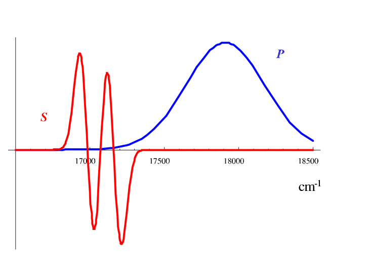
We require an transition scheme with the following properties: a) For the general DJ algorithm should assume values. Here we consider for definiteness the case of (equivalent to two and three qubits). b) The Franck-Condon (FC) overlap between and should be as large as possible and roughly constant for all () and () pairs, in order to maximize the efficiency of coherent transfer by the pulses. c) By choosing a large frequency shift between the P and S pulses it is guaranteed that the single time-circuit diagram of Fig. 1 describes the CARS process. The following values satisfy the above criteria: ; for , and for . The product of FC factors characterizes the overall strength of the transitions. The product is largest and roughly constant around , which motivates our choice of the values. In Fig. 2, we show the chosen pulse-shapes for P and S in the frequency domain for . P is broad, covering . S is red-shifted, and phase-masked. Fig. 2 shows the effect of the mask, corresponding to a balanced function . Both the P pulse, and the S pulse before masking have durations of fs. The P’ pulse which must provide vibrational selectivity, is the same color as S but its duration is taken to be 1 ps.
5 Simulations
We use Morse functions for the and electronic potentials with parameters =12550 cm-1, =2.666 Å, =1.858Å-1, =4500 cm-1, =3.016 Å, =1.850Å-1, the energy difference between the minima of the potentials is 15647 cm-1 (see Fig. 1). We calculate the vibrational eigenfunctions on both surfaces using the sinc-DVR method, and obtain the FC factors [27]. The time-evolution is explicitly integrated using the energy-representation. Time-ordering of the P and S pulses was not enforced: contributions from (P,S) and (S,P) sequences were added coherently. Only the Liouville pathway depicted in Fig. 1 was taken into account. No decoherence mechanism was included (decoherence, which occurs with , can be neglected on the execution time-scale of 1-2 ps). After the application of the two pulses, the prepared vibrational coherence (which is an explicit functional of the phase mask and the delay between the P and S pulses) preserves its magnitude and oscillates with the beat-frequency. By explicit calculation of the time-integrated CARS spectrum, using the perturbative evaluation of as described in detail in Ref. [4], we verify that the experimentally observable spectral component is proportional to . In what follows we simply consider as the signal.
6 Results
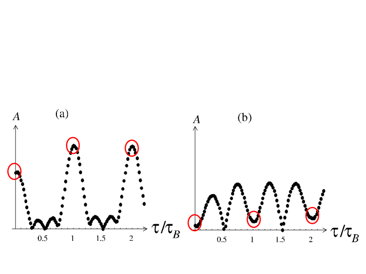
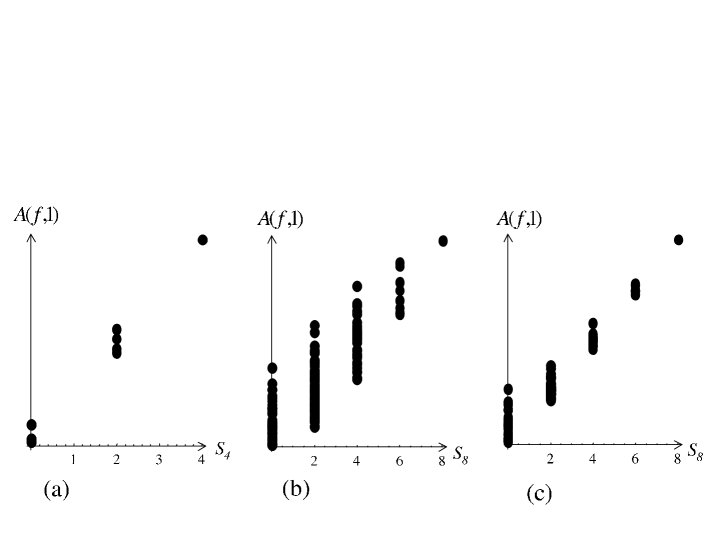
The signal as a function of delay-time between the P and S pulses was computed for all different phase-masks (i.e., for all possible different encoded functions, including those that are neither constant nor balanced). Fig. 3 shows the signals as functions of the delay time between the P and S pulses for a constant and a balanced function. For the constant function (left) the signal is large at integer multiples of the () period, while the signal is close to zero for the balanced function (right). This is therefore a clear experimental signature that distinguishes constant from balanced functions. Notice, however, that the signal from the balanced function is not exactly zero. In Fig. 4a, we show the signal for all different encoded functions vs. [Eq. (1)] (only points are actually shown, since the signal is symmetric in ). For balanced functions , so they should yield zero signal. For the two constant functions , so they should give maximal signal. For the other functions , so they should give half the signal amplitude. In reality, as expected from Fig. 3, there is a spread along the signal axis, indicating that not all balanced functions yield exactly zero signal. Fig. 4b shows the results for case. Here the spread of signals corresponding to the same class of functions is significantly larger, thus reducing the fidelity of distinguishing constant from balanced functions. It is useful to introduce a formal fidelity measure in order to quantify the performance of the algorithm. Perhaps the simplest measure is the distinguishability , which we define as the ratio of signal strengths
| (2) |
where the maximum is taken over all balanced signals. In the ideal case all so . A second measure is the Pearson’s correlation coefficient for a straight line interpolation between the signal and , which also accounts for the spread in the other (neither constant nor balanced) functions. This measure is important in case one decides to use our algorithm to also distinguish these other functions. In Table 1 we present these fidelities for different values and for different delay times. The reasons leading to a degradation in fidelity are the following: I) Non-uniform FC factors, causing different to be transferred with slightly different amplitude by the and S pulses. II) Spectral breadth of the laser-pulses, with the same consequence as I). These effects lead to non-uniformity in the prepared and projected coherent superpositions, thus misrepresenting and somewhat. III) Anharmonicity of the potential, leading to wavepacket dispersion on both the and potentials. In order to explore these effects, we performed simulations for the case, where all FC factors were artificially set equal (a pulse achieving this effect can in principle be shaped by amplitude masking), and the P pulse was spectrally broadened, by reducing its duration to fs. We refer to this as the “tailored” case. The results are presented in Fig. 4c, and the improvement in distinguishability is remarkable. This convincingly demonstrates the role of the non-uniform superposition in fidelity degradation. The solution, a spectrally broader P pulse together with tailoring the amplitudes of the P and S pulses to compensate for the non-uniformity of the FC factors, greatly improves the fidelity of the algorithm. To test the role of anharmonicity we also performed simulations at delays . Obviously, at zero delay anharmonicity cannot play a role. On the other hand anharmonicity should be more significant at than at . These expectations are confirmed in Table 1: a significant improvement in fidelity is seen when comparing the bare results to the tailored results, but only for . In contrast, for the fidelity remains low. The degradation for large values at large delay should be attributed to wavepacket dispersion due to anharmonicity. The simple solution is to apply the S pulse at or . The choice is actually preferable since interference from the time-reversed (S,P) sequence at , as well as higher order processes (6-wave mixing etc.) not accounted for in our simulations, lead to smaller signal strength. Optimization of the phases of the S and P pulses (chirping) is another option that can be used for compensating for anharmonicity effects [28].
7 Discussion and Conclusions
The CARS-QC proposal [4] is a promising new implementation of quantum logic, with potential near-term implications for quantum communication. Our main purpose in this work was to test the feasibility of this proposal by studying in detail the implementation of a benchmark quantum algorithm. We chose the Deutsch-Jozsa (DJ) problem for its conceptual and technical simplicity, and devised a modified algorithm that only requires quantum interference, not entanglement. This allowed us to directly test aspects related to the preparation of input vibrational superposition states and their dynamical evolution. To maintain fidelity, it is necessary to devise pulses that compensate for non-uniform Franck-Condon factors and counteract anharmonicity effects. These can be achieved through amplitude masking and frequency chirping using spatial light modulators [29], to optimally tailor the fields for a given choice of delay between pulses. Here, we have indicated that intuitively obvious pulses already allow a clear demonstration of how computational algorithms may be implemented in TFRCARS. The strategy in the laboratory demonstration of this, and similar algorithms involving rotation-vibration-electronic qubits, will be to rely on genetic algorithms to design pulses optimized for particular tasks [30, 31, 32].
Acknowledgements
D.A.L. gratefully acknowledges support from NSERC. The QC effort at Irvine is supported through the US AFOSR, under grant F49620-01-1-0449.
References
- [1] D.G. Cory, R. Laflamme, E. Knill, L. Viola, T.F. Havel, N. Boulant, G. Boutis, E. Fortunato, S. Lloyd, R. Martinez, C. Negrevergne, M. Pravia, Y. Sharf, G. Teklemariam, Y.S. Weinstein, W.H. Zurek, NMR Based Quantum Information Processing: Achievements and Prospects, Fortschritte der Physik 48 (2000) 875.
- [2] C. A. Sackett, D. Kielpinski, B. E. King, C. Langer, V. Meyer, C. J. Myatt, M. Rowe, Q. A. Turchette, W. M. Itano, D. J. Wineland, and C. Monroe, Experimental entanglement of four particles, Nature 404 (2000) 256.
- [3] A. Rauschenbeutel, G. Nogues, S. Osnaghi, P. Bertet, M. Brune, J.M. Raimond, and S. Haroche, Coherent Operation of a Tunable Quantum Phase Gate in Cavity QED, Phys. Rev. Lett. 83 (1999) 5166.
- [4] R. Zadoyan, D. Kohen, D.A. Lidar, and V.A. Apkarian, The manipulation of massive ro-vibronic superpositions using time-frequency-resolved coherent anti-Stokes Raman scattering (TFRCARS): from quantum control to quantum computing, Chem. Phys. 266 (2001) 323.
- [5] D. Deutsch and R. Jozsa, Rapid Solution of Problems by Quantum Computation, Proc. Roy. Soc. London Ser. A 439 (1992) 553.
- [6] I.L. Chuang, L.M.K. Vandersypen, X. Zhou, D.W. Leung and S. Lloyd, Experimental realization of a quantum algorithm, Nature 393 (1998) 143.
- [7] J.A. Jones and M. Mosca, Implementation of a Quantum Algorithm to Solve Deutsch’s Problem on a Nuclear Magnetic Resonance Quantum Computer, J. Chem. Phys. 109 (1998) 1648.
- [8] N. Linden, H. Barjat and R. Freeman, An implementation of the Deutsch-Jozsa algorithm on a three-qubit NMR quantum computer, Chem. Phys. Lett. 296 (1998) 61.
- [9] K. Dorai, Arvind and A. Kumar, Implementing quantum-logic operations, pseudopure states, and the Deutsch-Jozsa algorithm using noncommuting selective pulses in NMR, Phys. Rev. A 61 (2001) 042306.
- [10] R. Marx, A.F. Fahmy, J.M. Myers, W. Bermel and S.J. Glaser, Approaching five-bit NMR quantum computing, Phys. Rev. A 62 (2000) 012310.
- [11] J. Kim, J.-S. Lee, S. Lee, and C. Cheong, Implementation of the refined Deutsch-Jozsa algorithm on a three-bit NMR quantum computer, Phys. Rev. A 62 (2000) 022312.
- [12] S. Takeuchi, Experimental demonstration of a three-qubit quantum computation algorithm using a single photon and linear optics, Phys. Rev. A 62 (2000) 032301.
- [13] J. Vala, Z. Amitay, B. Zhang, S.R. Leone, and R. Kosloff, Experimental Implementation of the Deutsch-Jozsa Algorithm for Three-Qubit Functions using Rovibrational Molecular Wave Packets Representation, eprint quant-ph/0107058.
- [14] P. Chen, C. Piermarocchi, and L. J. Sham, Control of Exciton Dynamics in Nanodots for Quantum Operations, Phys. Rev. Lett. 87 (2001) 067401.
- [15] S. Mukamel, Principles of Nonlinear Optical Spectroscopy, Oxford Univ. Press, Oxford, 1995.
- [16] R. Zadoyan and V.A. Apkarian, Imaging the molecular rovibrational coherence through time-gated, frequency-resolved coherent anti-Stokes Raman scattering, Chem. Phys. Lett. 326 (2000) 1.
- [17] D.P. DiVincenzo, The Physical Implementation of Quantum Computation, Fortschritte der Physik 48 (2000) 771.
- [18] D. Deutsch, A. Ekert, R. Jozsa, C. Macchiavello, S. Popescu and A. Sanpera, Quantum privacy amplification and the security of quantum cryptography over noisy channels, Phys. Rev. Lett. 77 (1996) 2818, erratum - ibid. 80 (1998), 2022.
- [19] S. Rice, M. Zhao, Optical Control of Molecular Dynamics, John Wiley, NY, 2000.
- [20] A.P. Peirce, M.A. Dahleh, H. Rabitz, Optimal control of quantum-mechanical systems: Existence, numerical approximation, and applications, Phys. Rev. A 37 (1988) 4950.
- [21] C. M. Tesch, L. Kurtz, R. de Vivie-Riedle, Applying optimal control theory for elements of quantum computation in molecular systems, Chem. Phys. Lett. 343 (2001) 633.
- [22] J. P. Palao, R. Kosloff, Molecular quantum computing by an optimal control algorithm for unitary transformations, quant-ph/0204101 (2002).
- [23] A.N. Naumov, A. Materny, W. Kiefer, M. Motzkus, A.M. Zhelticov, Reversible Computations and Ultrafast Logic Gates by Coherent Multiwave Mixing Supplemented with Quantum Control, Laser Physics 11 (2001) 1319.
- [24] V.V. Lozovoy and M. Dantus, Photon echo pulse sequences with femtosecond shaped laser pulses as a vehicle for molecular-based quantum computation, Chem. Phys. Lett. 351 (2002) 213.
- [25] See for example R. Cleve, A. Ekert, C. Macchiavello and M. Mosca, Quantum algorithms revisited, Proc. Roy. Soc. London Ser. A 454 (1998) 339.
- [26] D. Collins, K.W. Kim, and W.C. Holton, Deutsch-Jozsa algorithm as a test of quantum computation, Phys. Rev. A 58 (1998) 1633.
- [27] D.T. Colbert and W.H. Miller, A novel discrete variable representation for quantum mechanical reactive scattering via the S-matrix Kohn method, J. Chem. Phys. 96 (1992) 1982.
- [28] C.J. Bardeen, J. Che, K.R. Wilson, V.V. Yakovlev, V.A. Apkarian, C.C. Martens, R. Zadoyan, B. Kohler, M. Messina, Quantum control of I2 in the gas phase and in condensed phase solid Kr matrix, J. Chem. Phys. 106 (1997) 8486.
- [29] A.M. Weiner, Femtosecond optical pulse shaping and processing, Prog. Quantum Electronics 19 (1995) 161.
- [30] R.S. Judson and H. Rabitz, Teaching lasers to control molecules, Phys. Rev. Lett. 68 (1992) 1500.
- [31] T. Brixner, A. Oehrlein, M. Strehle, G. Gerber, Feedback-controlled femtosecond pulse shaping, Appl. Phys. B 70 (2000) S119.
- [32] Feedback control for shaping of pulses but using acousto-optic-modulation (AOM) has also been implemented: C. J. Bardeen, V. V. Yakovlev, K. R. Wilson, S. D. Carpenter, P. M. Weber, W. S. Warren, Feedback quantum control of molecular electronic population transfer, Chem. Phys. Lett. 280 (1997) 151.
| 4 | 99/86 | 99/90 | 99/85 |
|---|---|---|---|
| 6 | 95/79 | 95/78 | 91/69 |
| 8 | 84/60 | 84/62 | 73/41 |
| 8t | 99/89 | 97/73 | 81/43 |