Optimum detection for extracting maximum information from symmetric qubit sets
Abstract
We demonstrate a class of optimum detection strategies for extracting the maximum information from sets of equiprobable real symmetric qubit states of a single photon. These optimum strategies have been predicted by Sasaki et al. SasakiBarnettJozsa99 . The peculiar aspect is that the detections with at least three outputs suffice for optimum extraction of information regardless of the number of signal elements. The cases of ternary (or trine), quinary, and septenary polarization signals are studied where a standard von Neumann detection (a projection onto a binary orthogonal basis) fails to access the maximum information. Our experiments demonstrate that it is possible with present technologies to attain about 96 % of the theoretical limit.
pacs:
03.67.Hk, 03.65.Ta, 42.50.–pI Introduction
In communications systems a sender, Alice, represents messages, for example the alphabet , by a given set of letters such as . She transmits sequences of the letters, in the form of codewords, through a communication channel. A receiver, Bob, detects codewords and thereby retrieves the message. To design an optimum communication system, one should first know basic properties of distinguishing the letter set over a channel. These are specified by conditional probabilities that Bob finds the outcome when Alice selected the letter . The matrix of these conditional probabilities, , is called the channel matrix. All the physical properties of the channel and of the detector are modeled through this channel matrix.
When a communication system operates in quanta, the channel matrix will be determined by the rules of quantum mechanics. The physical carrier conveying a letter should explicitly be described by a quantum state , which we refer to as the letter state. For example, if the letters are conveyed by weak pulses of laser light, the corresponding quantum states are usually nonorthogonal coherent states. Such nonorthogonal states can never be distinguished perfectly, even in principle. Therefore even if a channel and a detector are completely noiseless, quantum mechanics imposes an inevitable source of error or ambiguity in signal detection.
A detection process is represented mathematically by the probability operator measure (POM), which consists of nonnegative (generally not normalized) Hermitian operators satisfying the resolution of the identity Helstrom_QDET ; Holevo_book ; Peres_book :
| (1) |
Each element is associated with the measurement outcome and hence implies the output letter . If a channel is noiseless and hence quantum limited, then the channel matrix is given by
| (2) |
The primary concern in quantum communication is to determine the optimum detection strategy to distinguish among the letter states . Each state encodes the classical information embodied in the classical letter , which is selected with known prior probability .
The meaning of ‘optimum’ depends on a task that we are going to do. The simplest requirement is that Bob wants to decide which letter state he has received among the set with the smallest error. This usually means minimizing the average error probability, or bit error rate Holevo73_condition ; YuenKennedyLax75 . A second possibility is for Bob to eliminate all errors by allowing the possibility of inconclusive results by means of unambiguous state discrimination Ivanovic87 ; Dieks88 ; Peres88 ; Jaeger95 ; Barnett97RSL ; CheflesBarnett98 ; Chefles98_USD ; CheflesContemp . The optimum strategy in this case will be the one that minimizes the probability of inconclusive outcomes. This type of detection has been proposed for quantum key distribution HuttnerPeres .
For the communication of messages, however, Bob does best by devising a detection strategy so as to retrieve Alice’s message with the greatest probability. This does not necessarily mean minimizing either or , but instead means reducing the uncertainty in some random variable . Such a detection strategy is directly related to reliable communication by coding technique and is actually used as a basic building block for effective decoding procedures of codeword states formed from the letter states . (A more detailed explanation of this point is given in Appendix.)
The reduction of the uncertainty caused by a detection is quantified by the Shannon mutual information between the input (Alice’s) and output (Bob’s) random variables, and . This mutual information can be regarded as the amount of information extracted from . Bob’s optimum strategy will be the one that maximizes . Other figures of merit have also been considered and these include the fidelity Schumacher95 ; Claire01 .
The optimum conditions are already known for minimizing the error probability Holevo73_condition ; YuenKennedyLax75 . It is not an easy task, however, to find the optimum detection strategies from these conditions. In fact, optimum strategies are only known for some special cases such as the set of binary states, sets of symmetric states Holevo73_condition ; YuenKennedyLax75 ; Osaki96_OptPOM ; BanKurokawa97_SqRt ; Sasaki98a and multiply symmetric states Barnett01 . Unambiguous state discrimination is possible if and only if the letter states are linearly independent and an explicit method for constructing the optimum strategy has been given in this case Chefles98_USD ; CheflesContemp . Finding optimum solutions for is much more difficult than those for and due to the nonlinearity of logarithmic function of with respect to a POM. Optimum solutions are known only for the set of binary pure states Levitin95_QCM94 ; Osaki2000_QCM98 and for sets of real symmetric qubit states with equal prior probabilities Davies78 ; SasakiBarnettJozsa99 .
It seems intuitively reasonable that we might obtain most information by minimizing either the average error probability or the probability of inconclusive outcomes . In fact, the maximum mutual information for binary states is attained by the same strategy that realizes the minimum average error probability. There are, however, cases where the maximum information must be obtained neither by minimizing nor Davies78 ; SasakiBarnettJozsa99 ; Shor2001 .
Devices capable of demonstrating near optimum detection at the single photon level have been demonstrated in the laboratory. The simplest of these is discrimination between the set of binary photon polarization states with the minimum allowed average error probability Barnett97_exp . Unambiguous discrimination between two non-orthogonal polarization states has also been demonstrated Huttner96a ; Clarke00a . A set of more than three polarization states is linearly dependent and hence it is not possible to carry out unambiguous state discrimination. Clarke et al. have demonstrated state discrimination with near minimum error probability for both the trine and tetrad polarization states Clarke01b . They have also demonstrated the ability to extract more information than is possible by the best, standard von Neumann measurement (a projection onto binary orthogonal polarization states).
In this paper we describe our experimental implementation of a class of optimum strategies for maximizing the mutual information, as predicted by Ref. SasakiBarnettJozsa99 . One of these is the ternary or trine set of states discussed by Clarke et al. Clarke01b . We have improved upon the information yield obtained by these authors and have also measured the information obtained from signals formed from five and seven possible polarizations. Our letter states are implemented physically as single photon polarizations. The required equiprobable real symmetric qubit states are then states of linear polarization. Such sets of states have previously found application in quantum key distribution PhoenixTownsend95 ; PhoenixBarnettChefles00 . From the view point of fundamental interests, they might be the simplest system with which to test the peculiar effect predicted by Davies’ theorem. According to the theorem, there must exist at least one solution, that maximizes the mutual information, which has possible outputs, where is bounded by with being the dimension of the Hilbert space supported by Alice’s set Davies78 . For real state sets, this bounding inequality becomes SasakiBarnettJozsa99 . Thus for a single photon polarization system, one can always optimize the mutual information by constructing a device with just three possible outputs. This is true regardless of the number of letter states. In the case of ternary or trine signals, the optimum measurement consists of three symmetric state vectors with the length less than the unity, and has been demonstrated experimentally in Ref. Clarke01b . In the cases of quinary and septenary signals, the optimum strategies consist of three nonorthogonal state vectors with different lengths. In the septenary case, there are two different configurations of measurement state vectors. We study how each of these strategies work and the extent to which they allow us to access the theoretical maximum amount of mutual information.
II Real symmetric qubit sets and optimum detection
Let be the orthogonal basis of linear polarization states of a single photon. Then the real symmetric qubit states are defined as
We assume that each state is selected with equal prior probability . This set is one of the few quantum state sets for which optimum strategies for the accessible information are explicitly known Levitin95_QCM94 ; Osaki2000_QCM98 ; Davies78 ; SasakiBarnettJozsa99 .
For , the signal states cannot be distinguished perfectly, thus . The minimum average error probability is
| (4) |
which is attained by the POM Helstrom_QDET ; BanKurokawa97_SqRt
| (5) | |||||
This POM is unique in leading to the minimum error probability and has the same number of POM elements, corresponding to the measurement outcomes, as the letter states.
In contrast, maximizing the mutual information requires a POM with three rank-one elements at most, corresponding to just three measurement outcomes SasakiBarnettJozsa99 . Although it is also possible to construct optimum POMs with elements more than three, a strategy with minimum outputs is often the one desired in practice.
If is even, a von Neumann measurement, i.e. a pair of orthogonal projectors, can be the optimum strategy with minimum outputs. If is odd, then at least three outputs are required and a standard von Neumann measurement fails in maximizing the mutual information. The three rank-one elements required for the optimum POM are specified as follows:
| (7) | |||||
| with | (11) |
where is determined from
| (12) |
for an integer parameter within the range . We will refer to the unnormalized vectors given in Eq. (11) as measurement state-vectors.
| 0 | 0.5 | 0.5 | |
| 0.5 | 0 | 0.5 | |
| 0.5 | 0.5 | 0 |
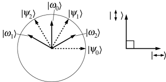
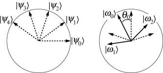
In the case of (ternary or trine), the optimum POM is given by which results in the set of three measurement state-vectors with equal norms. The signal and measurement state-vectors are schematically shown in Fig. 1. In this figure, each arrow represents the polarization direction where the horizontal and the vertical directions correspond to the two unit bases and , respectively. The length of each arrow represents the norm of the associated state vector, e.g. or .
The optimum measurement in this case means that the state vectors and are orthogonal, and thus
| (13) |
The other two possible measurement outcomes occur with equal probabilities. This situation is summarized in Table 1.
In the cases of (quinary) and (septenary), Eq. (11) results in the three measurement state-vector with two distinct norms. The relationship between the quinary letter states and the three measurement state-vectors (with ) is depicted in Fig. 2.
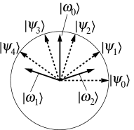
The channel matrix in this case is summarized in Table 2.
| 0 | 0.309 | 0.809 | 0.809 | 0.309 | |
| 0.5 | 0.191 | 0 | 0.191 | 0.5 | |
| 0.5 | 0.5 | 0.191 | 0 | 0.191 |
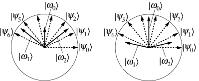
In the septenary case, there are two different POMs with three elements given by Eq. (11), with and in Eq. (12) respectively. They are depicted in Fig. 3 and summarized in Tables 4 and 4. In either case, there are combinations of that give , although is not necessarily equal to (a difference from the ternary case).
| 0 | 0.069 | 0.223 | 0.346 | 0.346 | 0.223 | 0.069 | |
| 0.5 | 0.154 | 0 | 0.154 | 0.5 | 0.777 | 0.777 | |
| 0.5 | 0.777 | 0.777 | 0.5 | 0.154 | 0 | 0.154 |
| 0 | 0.178 | 0.579 | 0.901 | 0.901 | 0.579 | 0.178 | |
| 0.5 | 0.322 | 0.099 | 0 | 0.099 | 0.322 | 0.5 | |
| 0.5 | 0.5 | 0.322 | 0.099 | 0 | 0.099 | 0.322 |
The method to implement the optimum POM with minimum outputs, as given in Eq. (11), is prescribed in detail in Ref. SasakiBarnettJozsa99 . In short, the nonorthogonal measurement basis is considered as the projection of a three-dimensional orthonormal basis in an enlarged space. Such an enlarged space is achieved by introducing another independent binary basis.
In practice, the concept described above is realized as the polarization Mach–Zehnder interferometer shown in Fig. 4. The four-dimensional space is composed of , where subscripts represent the optical paths () indicated in Fig. 4. Our letter states present in the subspace spanned by the first two of these vectors. The additional port (at in Fig. 4) with an input of vacuum state enlarges the space.
The unitary operation of the Mach–Zehnder part (indicated as in Fig. 4) can be written as
| (14) | |||||
| (27) | |||||
where is twice the angle of HWP1. (This represents the angle of one of the unit basis in the enlarged space relative to the signal plane.) In our setup, the inputs are and hence . Thus the apparatus of Fig. 4 actually couples a three-dimensional state space.
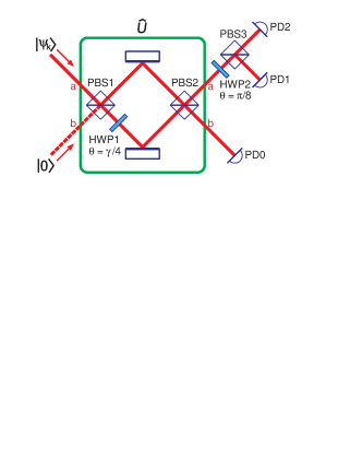
PD0 detects components whose amplitude is given by
| (28) |
Its null result guarantees that the signal was not . On the other hand, and components are further mixed at HWP2 and PBS3, resulting in amplitudes of
| (29) |
which are then detected at PD1 and PD2. By inspecting Eqs. (28) and (29), it can be seen that given in Eq. (11) were reproduced. When the condition Eq. (12) is satisfied, the null result at PD1 or PD2 excludes one of the possible signals ( with and ).
III Experiment
The principle described in the previous section is realized in an actual setup to confirm the theoretical results. In the experiment, the polarization basis correspond to P- (within the paper plane in Fig. 5) and S- (perpendicular to the paper plane) polarizations, respectively.
The light source is a He–Ne laser (Spectra–Physics, model 117A) operating at the wavelength of 632.8 nm. The laser light of 1 mW is first attenuated by the attenuator ATN1 by a factor of , purified to the horizontally polarized state by the polarizing beam splitter PBS0. The half waveplate HWP0, driven by a stepping motor, works as a modulator to produce the set . Then the beam is further attenuated by ATN2 by a factor of . At the input of the Mach–Zehnder interferometer, the light power is of order fW ( photon/sec). In other words, the beam contains about photons in one meter, whereas our detecting circuit is shorter than that.
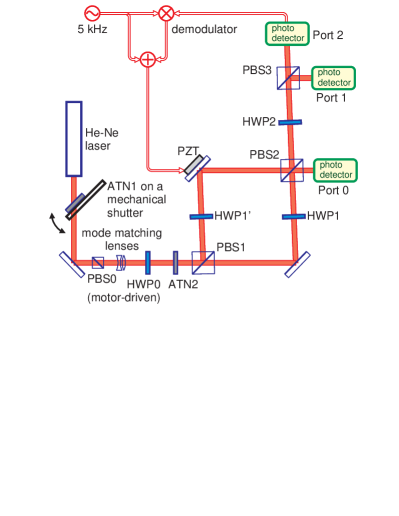
The polarization Mach–Zehnder interferometer is composed of two PBSs, PBS1 and PBS2. Each PBS is carefully mounted so as to operate with an extinction ratio of (see below and Ref. pmzexp ). Each path of the Mach–Zehnder contains one half waveplate, HWP1 and HWP. The angle of HWP1 is adjusted to a quarter of in Eq. (12) so that the polarization of the light is rotated by , whereas HWP is inserted for symmetry and thus adjusted not to affect the polarization state.
The beams from the two paths are superimposed at PBS2, resulting in two output beams from the Mach–Zehnder. The one corresponds to path in Fig. 4 is detected directly at Port 0. The beam in path in Fig. 4 is delivered to HWP2 at an angle of and then to PBS3, in order to visualize the interference of the beams from the two paths. The two outputs from PBS3 are detected at Ports 1 and 2.
The relative path length of the Mach–Zehnder is adjusted to be a proper operating point (which is the minimum at either of Port 1 or 2) by a PZT actuator through a feedback system utilizing the modulation-demodulation method. Once the relative path length is adjusted, a sample-and-hold circuit keeps the mirror position fixed during a measurement sequence (see below) which lasts typically 20–30 seconds.
There are two photodetectors at each port, a silicon photodiode and an APD (avalanche photodiode, EG & G, SPCM–AQ–141–FC) guided through a multimode optical fiber. The former is for alignment purpose (with increased light) and the photon counting process is carried out with the latter, by mechanically switching the beam between them. The coupling efficiency of the fiber is measured to be –, including the coupling lens and the connectors before the APD. The output from each APD is sent to a pulse counter (EG & G ORTEC, model 995) to count the number of photon-induced pulses.
The counters are activated simultaneously by a common trigger, typically of one-second duration and five-time repetition. The numbers of counts in each duration are read by a computer from all counters, so that we can analyze statistical errors. This procedure is repeated for each signal with , composing a full sequence of measuring the mutual information. The ratio of counts in the three APDs provides the channel matrix from which the mutual information is derived.
As is discussed in Section II, in the optimum detection scheme proposed, the mutual information is increased by excluding one of the possible signals. Thus, realizing zero probabilities at the output ports is essential in achieving a high mutual information. In practice, however, there are several causes that increase the probability at the output where ideally zero is expected. Among them, the most pronounced ones are the pulses from an APD without any light (APD error), the finite extinction ratio of a PBS (PBS error), and the finite contrast of interference (interferometer error).
Without any light at all, the average dark counts of the APDs were measured to be slightly less than 100 count/sec. Although the whole interferometer is enclosed in a box, the environmental light increases the number of counts to around 300 count/sec, even if no laser light is injected. When the laser light is injected, the leak light due to the imperfection of the interferometer is added, and was measured to the average count of around 1000 count/sec for the output port at which no count is expected ideally (see Tables 1–4). The last increment is considered as the contributions from the PBS errors and the interferometer error. At the ports for which finite counts are expected, we had the counts of order count/sec at most, which is within the linear range of APDs.
In general, a PBS has an angular-dependent separation of two polarization components. In our case, it turned out to be possible to achieve the separation better than for both polarization components, by carefully aligning the angle of incidence slightly ( rad) different from the standard value . Then the expected contrast is , which we thought sufficient for our experiment. We adopted this angle in our polarization Mach–Zehnder interferometer, resulting in a parallelogram arrangement (see Fig. 5).
The actual contrast obtained with this interferometer can be as high as
| (30) |
though the typical values under normal experimental conditions were slightly lower than this. Thus, this is limited not by the PBS imperfection but by, e.g., the spatial mode mismatch of the two beams.
In order to analyze the performance of our detecter circuit, we measured not only the mutual information of the optimum detection scheme but also its dependence on the relative angle between the signal set and the measurement state vectors . This is relevant to, for example, the possible rotation of polarization in the transmitting fiber. We measured the mutual information against the signal set where
as a function of the initial offset angle (the optimum detection corresponds to ). The relation between and is depicted in Fig. 6 for the case of quinary signals. In the experiment, was changed in steps of radian (two degrees).
IV Results


We carried out the optimum measurements described in Section II for the sources comprising the ternary (trine), quinary and septenary states. For the septenary signal states, both of the two optimum detection schemes (with and in Eq. (12) ) were tested.
Fig. 8 shows the relative output counts at the three detectors as the polarization of the input light is varied in the ternary case. This relative power corresponds to the probability for the measurement outcome to occur for a single input photon.


For the polarization angles we are performing the state discrimination with the minimum error probability, while for the angles we are realizing a measurement that allows unambiguous elimination of one possibility among the three letter states. These measurements were referred to as the trine and anti-trine measurements in Ref. Clarke01b . These authors found an rms deviation of from the theoretical value given in Table 1. Our results indicate a lower value of . The reason for our lower value is that we have been able to achieve a smaller PBS error.
The data depicted in Fig. 8 leads to the mutual information presented in Fig. 8. At the optimum operating point, corresponding to the best detection strategy, we clearly find that the mutual information exceeds that attainable with the best von Neumann measurement. Our value also exceeds that obtained earlier by Clarke et al. Clarke01b represented as triangles in our figure. The reason for this is again the smaller PBS error. Our experimental value is slightly lower than the theoretical maximum and this is due mainly to a residual PBS error of approximately and also to the imperfect contrast of interference. It was found pmzexp that despite the PBS error is not the limiting factor of the interference contrast, it has non-negligible effects on the mutual information.
Fig. 10 shows the relative output counts at our three detectors for the quinary case. These provide the data with which to calculate the mutual information depicted in Fig. 10. Our data show a marginal increase in the mutual information beyond the value that may be attained with the best von Neumann measurement. The difference between our experimental result and the theoretical value is again principally attributable to the PBS error and the imperfect contrast.
As mentioned earlier, the optimum detection scheme increases the amount of the mutual information by excluding one of the possible signals. With three detectors, only three signals can be excluded at most, and the remaining signals do not contribute the mutual information very much. This fact reduces the maximum mutual information in quinary case (and in septenary case as well) from that in ternary case. Although the absolute difference (of ) between the experimental and ideal values in the quinary case is similar to that in the ternary case, the excess from the von Neumann measurement became only marginal.

Fig. 11 shows the mutual informations derived with the two possible optimum detection schemes for the septenary case. Even in an ideal case, the increase in the attainable mutual information over that found using the best von Neumann measurement is quite small. In both cases our experimental values failed to reach even the value attainable by means of the best von Neumann measurement.
The result with shows a higher mutual information than that with . This difference is not by an experimental failure, but due to the difference in the influences of inperfect contrast between the two cases. The reduced contrast increases the light leaking towards the port where ideally no light is expected, which in turn reduces the mutual information. The absolute amount of leak light is proportional to the amount of light interfering. This qualitatively explains the difference of experimental results with and . In the former case the interfering light is greater than the latter, thus the influence on the mutual information is larger.
V Discussion and concluding remarks
Our ability to communicate classical information by means of a quantum channel is limited by the existence of non-orthogonal quantum states and the associated restrictions in discriminating among them. These factors are fundamental to quanta as distinct from classical information theory and make quantum key distribution possible PhoenixTownsend95 ; PhoenixBarnettChefles00 .
The optimum use of a quantum communication channel is closely related to the maximization of mutual information, as discussed in Appendix. The accessible information is obtained by maximizing the mutual information through the selection of the detection process. There are only a very few examples of signal states for which the accessible information is known Levitin95_QCM94 ; Osaki2000_QCM98 ; Davies78 ; SasakiBarnettJozsa99 . One such example is that of the real symmetric qubit states SasakiBarnettJozsa99 .
In this paper we have described our polarization Mach–Zehnder interferometer that was designed to extract the accessible information from signals formed from symmetric polarization states. For the ternary (trine) states, our results proved an amount of information close () to the theoretical limit. Our value for the mutual information exceeds that reported in an earlier experiment Clarke01b . The difference between our measured value for the mutual information and the theoretical limit is due principally to the leakage of the ‘wrong’ polarization through our polarizing beam splitters and also to the imperfect contrast. The effect of this leakage is more pronounced when we consider the quinary and septenary signal states. Our experiments suggest that optimum quantum communication based on the ternary (trine) polarization states, for example the quantum key distribution by the Phoenix–Barnett–Chefles protocol PhoenixBarnettChefles00 , should be feasible. Schemes based on the quinary and septenary states will present a greater challenge.
In the light of fundamental interests, the quinary and septenary states meet with the simplest cases where the maximum amount of information can be extracted by a detection in which the number of possible outputs is less than that of input states. Davies’ theorem predicted that a device with three possible outputs suffices for any real polarization system of a single photon. In our experiment, Davies’ theorem has been tested within the PBS error. For the complete confirmation, further study might be necessary, e.g. comparing the minimum-output optimum detection with the one corresponding the group covariant optimal solution which consists of the same number of outputs as inputs.
Acknowledgements.
We are grateful to Dr. Izutsu, Professor Hirota, Dr. Riis, and Dr. Clarke for discussion and encouragement. This work was supported, in part, by the British Council, the Royal Society of Edinburgh, and by the Scottish Executive Education and Lifelong Learning Department.*
Appendix A Mutual information
In this Appendix we give the definition of the mutual information and explain its functional meaning. Primary concerns of information theory are how to represent messages as effectively as possible and how to transmit messages as precisely as possible. The mutual information is related with the second problem.
A sender has a source of messages and selects one of a known set with given prior probabilities . This source may be characterized by the random variable . The sender represents each of these messages by a sequence of a given set of letters such as . These are the symbols running through the transmission channel. Each message is then represented by a codeword formed from a sequence of letters. This is source coding. Information theory tells us that the effectiveness of source coding can be measured by the minimum of the average length required for a codeword and that it is given by the Shannon entropy
| (32) |
This is a measure of uncertainty in the random variable . It takes its maximum value when all elements appear with equal probability, that is, when we know nothing better than a random guess for each element. This measure of uncertainty is regarded as the amount of information required to represent .
A channel is usually subject to various types of noise disturbances. Information theory provides means and limits for reliable information transmission with such noisy channels. The key idea is to introduce some redundancy in the codeword representation prior to transmission so as to allow the correction of errors at the receiving side. This entails adding some redundant letters to the codewords and hence increases their length. This is channel coding. The mutual information quantifies how much redundancy is required for error-free transmission.
The output from the source encoder is a sequence of the letters forming the codewords representing the messages. For such sequences one can find the frequencies of appearance for each letter . Thus we can define a random variable for the outputs from the source encoder. This is the set of inputs to the channel. A mathematical model for the channel is specified by the set of possible outputs and the conditional probability for each input. Given , , and , we can determine the existence or nonexistence of encoders and decoders that achieve a given level of transmission performance.
The mutual information is defined between the input and output random variables and . Here
| (33) |
is the probability of having . The uncertainty of the input random variable is measured by the Shannon entropy
| (34) |
defined in a similar way to Eq. (32).
If the receiver detects the output signal , then he is now more certain about . The new probability distribution conditioned by is given as
| (35) |
One can then define the average conditional entropy by
| (36) |
This quantifies the remaining uncertainty of after having the knowledge on the conditioning variable . The information extracted by the receiver is naturally defined by the reduction of the uncertainty,
| (37) | |||||
This is the mutual information between and .
Now let us consider a block coding of length . The output from the source encoder is a letter sequence, which is devided into blocks (message blocks) of length (). Each block is supplemented by an additional block (correction block) of letters to compose a transmission codeword :
where each is an element of possible letters . Note that although there are possible sequences of length in total, only part of them, i.e. sequences, are used as codewords. This redundancy, together with appropriate choice of correction blocks, allows us to recover the possible errors in transmission.
The input codeword will be disturbed in the channel so as to come out as a different sequence . The channel decoder processes this output codeword to assign an appropriate sequence which should be the correct input codeword. The average error in this decoding should be as small as possible, while the redundancy should also be as small as possible. In other words, keeping the ratio , so-called the transmission rate, as large as possible, we wish to attain a small error in decoding.
Let us suppose that encoding is made under the constraint that the frequency of ’s occurring in the set of codewords is . Information theory says that by an appropriate design of the coding scheme it is possible to transmit the messages with an error probability as small as desired if is satisfied. For the fixed channel model , one may further adjust prior probabilities to maximize the mutual information. The maximum value
| (39) |
is called the channel capacity. Then the channel coding theorem tells us Shannon48 ; Gallager_book ; Cover&Thomas_book that if holds there exists a coding scheme which transmits messages with an error probability as small as desired. Thus the mutual information is related to the ultimate use of the channel.
The basic frameworks described above also apply to a quantum limited channel. However a new ingredient comes into play, which is a quantum effect in the detection process. Let us consider the simplest case where the letter set is conveyed by a set of pure states , possibly a nonorthogonal set, through a noiseless channel. Then the channel model is specified by a POM and the channel matrix . The POM describes the measurement process and gives it a quantum prescription for generating the output letters .
In the conventional (classical) context, the channel matrix is given and fixed. In quantum domain, however, one may ask what is the best possible POM for the given set of letter states . This is actually a nontrivial problem as discussed in Introduction. The problem can be decomposed into several steps. First we can consider the maximization of the mutual information with respect to a POM for the fixed and prior probabilities . The maximum value
| (40) |
is called the accessible information of . We can then consider the maximization of the accessible information over prior probabilities , and may define the quantity as
| (41) |
This would be a natural extension from the conventional idea. However, this is not in general the maximum bound for the transmission rate for error-free communication, and hence it is not the channel capacity. In fact, there is the peculiar quantum interference effect in quantum detection of codeword states, which was not taken into account in the conventional theory. The true capacity for a pure state channel is given by Hausladen et al. Hausladen96_coding . The general theory for a mixed state channel is given by Holevo Holevo96_coding1 and by Schumacher and Westmoreland Schumacher97_coding .
To realize reliable transmission ensured by quantum theory of the channel capacity, one may need quantum computation for the decoding process Sasaki98a ; Sasaki98_realization . This is, however, far beyond present technologies. If only a quantum detection on each letter state is available, then and practically specify the limit of communication ability. Let us suppose again that encoding is made such that (i.e. ) occurs in the set of codewords (i.e. ) with the probability . We further suppose that is the POM attaining the accessible information for and the receiver applies this detection separately on each letter states to get output sequences . If holds, then a reliable transmission of the letters with an arbitrarily small error is possible by an appropriate classical coding. The optimum POM for the accessible information is thus an important concern for devising a good code for a quantum limited channel.
References
- (1) C.W. Helstrom, Quantum Detection and Estimation Theory (Academic Press, New York, 1976).
- (2) A.S. Holevo : Probabilistic and Statistical Aspects of Quantum Theory (North-Holland, Amsterdam, 1982).
- (3) A. Peres: Quantum Theory: concepts and methods, 279 (Kluwer Academic Publishers, Dortrecht, 1993).
- (4) A.S. Holevo, J. Multivar. Anal. 3, 337 (1973).
- (5) H.P. Yuen, R.S. Kennedy, and M. Lax, IEEE Trans. Inf. Theory 21(2), 125 (1975).
- (6) I.D. Ivanovic, Phys. Lett. A 123, 257 (1987).
- (7) D. Dieks, Phys. Lett. A 126, 303 (1988).
- (8) A. Peres, Phys. Lett. A 128, 19 (1988).
- (9) G. Jaeger and A. Shimony, Phys. Lett. A 197, 83 (1995).
- (10) S.M. Barnett, Phil. Trans. R. Soc. Lond. A 255, 2279 (1997).
- (11) A. Chefles and S.M. Barnett, J. Mod. Opt., 45, 1295 (1998).
- (12) A. Chefles, Phys. Lett. A 239, 339 (1998).
- (13) A. Chefles, Contemp. Phys. 41, 401 (2000) and references therein.
- (14) B. Huttner and A. Peres, J. Mod. Opt. 41, 2397 (1994).
- (15) B. Schumacher, Phys. Rev. A 51, 2738 (1995).
- (16) S.M. Barnett, C.R. Gilson, and M. Sasaki, J. Phys. A: Math. Gen. (in press).
- (17) M. Osaki, M. Ban, and O. Hirota, Phys. Rev. A 54, 1691 (1996).
- (18) M. Ban, K. Kurokawa, R. Momose, and O. Hirota, Inter. J. Theor. Phys. 36, 1269 (1997).
- (19) M. Sasaki, K. Kato, M. Izutsu, and O. Hirota, Phys. Rev. A 58, 146 (1998).
- (20) S.M. Barnett, Phys. Rev. A 64, 030303(R) (2001).
- (21) L.B. Levitin, Quantum Communication, and Measurement (Eds. V.P. Belavkin, O. Hirota, and R.L. Hudson, Prenum, New York, 1995), 439.
- (22) M. Osaki, M. Ban, and O. Hirota, Quantum Communication, Computing, and Measurement 2 (Eds. P. Kumar, G M. D’Ariano, and O. Hirota, Kluwer academic/Prenum publishers, New York, 2000) 17.
- (23) E.B. Davies, IEEE Trans. Inf. Theory IT-24, 596 (1978).
- (24) M. Sasaki, S.M. Barnett, R. Jozsa, M. Osaki, and O. Hirota, Phys. Rev. A 59, 3325 (1999).
- (25) P.W. Shor, “On the Number of Elements Needed in a POVM Attaining the Accessible Information”, to appear in Quantum Communication, Computing, and Measurement 3 (Eds. O. Hirota and P. Tombesi, Kluwer, Dordrecht, 2001). Also available as ArXiv:quant-ph/0009077.
- (26) S.M. Barnett and E. Riis, J. Mod. Opt. 44, 1061 (1997).
- (27) B. Huttner, A. Muller, J.D. Gautier, H. Zbinden, and N. Gisin, Phys. Rev. A 54, 3783 (1996).
- (28) R.B.M. Clarke, A. Chefles, S.M. Barnett, and E. Riis, Phys. Rev. A 63, 040305 (2001).
- (29) R.B.M. Clarke, V.M. Kendon, A. Chefles, S.M. Barnett, E. Riis, and M. Sasaki, Phys. Rev. A 64, 012303 (2001).
- (30) S.J.D. Phoenix and P.D. Townsend, Comtemp. Phys. 36, 165 (1995) and references therein.
- (31) S.J.D. Phoenix, S.M. Barnett, and A. Chefles, J. Mod. Opt. 47, 507 (2000).
- (32) J. Mizuno et al., paper in preparation (2001).
- (33) C.E. Shannon, Bell System Tech. J. 27, 379 (Part I) and 623 (Part II) (1948).
- (34) R.G. Gallager: Information Theory and Reliable Communication (John Wiley and Sons, New York, 1968).
- (35) T. Cover and J. Thomas: Elements of Information Theory (John Wiley and Sons, New York, 1991).
- (36) P. Hausladen, R. Jozsa, B. Schumacher, M. Westmoreland, and W.K. Wootters, Phys. Rev. A 54, 1869 (1996).
- (37) A.S. Holevo, IEEE Trans. Inf. Theory IT-44, 269 (1998).
- (38) B. Schumacher and M. Westmoreland, Phys. Rev. A 56, 131 (1997).
- (39) M. Sasaki, T.S. Usuda, M. Izutsu, and O. Hirota, Phys. Rev. A 58, 159 (1998).