Quantum Teleportation with a Complete Bell State Measurement
Abstract
We report a quantum teleportation experiment in which nonlinear interactions are used for the Bell state measurements. The experimental results demonstrate the working principle of irreversibly teleporting an unknown arbitrary quantum state from one system to another distant system by disassembling into and then later reconstructing from purely classical information and nonclassical EPR correlations. The distinct feature of this experiment is that all four Bell states can be distinguished in the Bell state measurement. Teleportation of a quantum state can thus occur with certainty in principle.
pacs:
PACS Number: 03.65.Bz, 03.67.Hk, 42.50.Dv, 42.65.KyThe idea of quantum teleportation is to utilize the nonlocal correlations between an Einstein-Podolsky-Rosen pair of particles [1] to prepare a quantum system in some state, which is the exact replica of an arbitrary unknown state of a distant individual system [2]. Three experiments in this direction were published recently [3, 4, 5].
The following conditions must be satisfied in any claim for quantum teleportation: (i) the input quantum state, which is teleported in the experiment must be an arbitrary state, (ii) there must be an output quantum state which is an “instantaneous copy” of the input quantum state, and (iii) the Bell state measurement (BSM) must be able to distinguish the complete set of the orthogonal Bell states so that the input state can be teleported with certainty.
In this Letter, we experimentally demonstrate a quantum teleportation scheme which satisfies all three of the above conditions. The input state is an arbitrary polarization state and the BSM can distinguish all four orthogonal Bell states so that the state has a certainty to be teleported in principle. This is because the BSM is based on nonlinear interactions which are necessary and non-trivial physical processes for correlating the input state and the entangled EPR pair [6, 7].
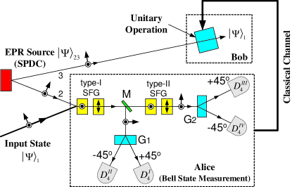
The basic elements of the experiment are schematically shown in Fig. 1. Just as the original proposal of quantum teleportation [2], it consists of four essential parts: (a) the input state, (b) the EPR pair, (c) Alice (who performs the BSM of the input state and her EPR particle), and (d) Bob (who carries out unitary operations on his EPR particle). The input quantum state is an arbitrary polarization state given by,
| (1) |
where and represent the two orthogonal linear polarization bases (specifically in this paper) (horizontal) and (vertical) respectively. and are two arbitrary complex amplitudes with respect to the and
bases and they satisfy the condition . The EPR pair shared by Alice and Bob is prepared by spontaneous parametric down conversion (SPDC) as,
| (2) |
with the subscripts 2 and 3 as labeled in Fig.1 [8]. The complete state of the three particles before Alice’s measurement is then,
| (3) | |||
| (4) |
The four Bell states which form a complete orthonormal basis for both particle 1 and particle 2 are usually represented as,
State (4) can now be re-written in the following form based on the above orthonormal Bell states,
| (5) |
To teleport the state of particle 1 to particle 3 reliably, Alice must be able to distinguish her four Bell states by means of the BSM performed on particle 1 and her EPR particle (particle 2). She then tells Bob through a classical channel to perform a corresponding linear unitary operation on his EPR particle (particle 3) to obtain an exact replica of the state of particle 1. This completes the process of quantum teleportation.
The distinct feature of the scheme shown in Fig.1 is that the BSM is based on nonlinear interactions: optical Sum Frequency Generation (SFG) (or “upconversion”). Four SFG nonlinear crystals are used for “measuring” and “distinguishing” the complete set of the four Bell states. Photon 1 and photon 2 may interact either in the two type-I crystals or in the two type-II crystals to generate a higher frequency photon (labeled as photon 4). The projection measurements on photon 4 (either at the or at the direction) correspond to the four Bell states of photon 1 and photon 2, and .
Let us now discuss the BSM in detail (see Fig.1). The first type-I SFG crystal converts two polarized photons into a single horizontal polarized photon . Likewise, the second type-I SFG crystal converts two polarized photons into a single vertical polarized photon . The first and the last terms on the right-hand side in Eq.(4) thus become,
Dichroic beamsplitter reflects only SFG photons to the polarization projector . Two detectors and are placed at the and output ports of respectively. Denoting the and polarization bases by and , the state may be re-written as,
| (6) | |||
| (7) |
which gives,
| (8) | |||||
| (9) |
i.e., if detector ( is triggered, the quantum state of Bob’s EPR photon (photon 3) is:
and, if detector ( is triggered, the quantum state of Bob’s photon is:
As we have analyzed above, the and the polarized type-I SFG components in Eq.(7) correspond to the superposition of and which are the respective Bell states and .
Similarly, the other two Bell states are distinguished by the type-II SFG’s. The states and are made to interact in the first and the second type-II SFG crystals respectively to generate a higher frequency photon with either horizontal (the first type-II SFG) or vertical (the second type-II SFG) polarization. A polarization projector is used after the type-II SFG crystals and two detectors and are placed at the and the output ports of respectively. On the new bases of and for the SFG photon, the second and the third terms on the right-hand side in Eq.(4) thus become,
| (10) | |||
| (11) |
which gives,
| (12) | |||||
| (13) |
i.e., if detector ( is triggered, the quantum state of Bob’s photon is:
and if detector ( is triggered, the quantum state of Bob’s photon is:
The and the polarized type-II SFG components correspond to the superposition of and which are the Bell states and respectively.
To obtain the exact replica of the state of Eq.(1), Bob needs simply to perform a corresponding unitary transformation after learning from Alice which of her four detectors, , , , or , has triggered [9].
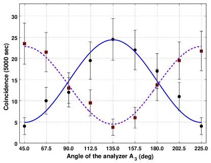
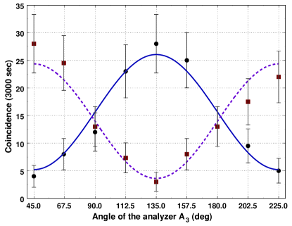
To demonstrate the working principle of this scheme, we measure the joint detection rates between detectors -, -, - and -, where is Bob’s detector (see Fig.4). In these measurements we choose the input state as a linear polarization state. For a fixed input polarization state, the angle of the polarization analyzer which is placed in front of Bob’s detector is rotated and the joint detection rates are recorded. Figure 2 shows two typical data sets for - and -. The input polarization state is . Clearly, these data curves confirm Eq.(9). The different phases of the two curves reflect the phase difference between the two states in Eq.(9). Experimental data for - and - show similar behavior, see Fig. 3, which confirm Eq.(13).
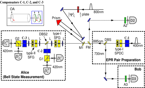
We now discuss the details of the experimental setup. The schematic of the experimental setup is shown in Fig. 4. The input polarization state is prepared by using a plate from a femtosecond laser pulse (pulse width 100fsec and central wavelength = 800nm) [10]. The EPR pair (730nm-885nm photon pair) is generated by two non-degenerate type-I SPDC’s. The optical axes of the first and the second SPDC crystals are oriented in the respective horizontal () and vertical () directions. The SPDC crystals are pumped by a polarized 100fsec laser pulse with 400nm central wavelength. The BBO crystals (each with thickness 3.4mm) are cut for collinear non-degenerate phase matching. Since the two crystals are pumped equally, the SPDC pair can be generated either in the first BBO as () or in the second BBO as () with equal probability (885 and 730 refer to the wavelengths in nanometer). In order to prepare an EPR state in the form of Eq.(2) (a Bell state), these two amplitudes have to be quantum mechanically “indistinguishable” and have the expected relative phase. A Compensator (C-1) is used for this purpose and it consists of two parts: a thick quartz rod and two thin plates. The thick quartz rod is used to compensate the time delay between the two amplitudes and the , and two thin quartz plates are used to adjust the relative phase between them by angular tilting. A dichroic beamsplitter is placed behind the SPDC crystals to separate and send the photon 2 (885nm) and photon 3 (730nm) to Alice and Bob respectively. To check the EPR state, a flipper mirror is used to send the photon 2 (885nm) to a photon-counting detector for EPR correlation measurement. Both the space-time and polarization correlations must be checked before teleportation measurements, in order to be certain of having high degree EPR entanglement and the expected relative phase between the and the amplitudes (see Ref.[11] for details). Once the EPR state in Eq.(2) is prepared, is flipped-down and photon 2 (885nm) is given to Alice for BSM with photon 1.
The BSM consists of four SFG nonlinear crystals, two projectors ( and ), four single photon counting detectors (, , , and ) and two compensators as well as other necessary optical components. The input photon (800nm) and photon 2 (885nm) may either interact in the two type-I or in the two type-II SFG crystals. Two pairs of lenses () are used as telescopes to focus the input beams onto the crystals. The vertical (horizontal) polarized amplitudes of the input photon (800nm) and the vertical (horizontal) polarized photon 2 (885nm) interact in the first (second) type-I SFG to generate a 420nm horizontal (vertical) polarized photon [12] . The horizontal (vertical) polarized amplitudes of the input photon and the vertical (horizontal) polarized photon 2 interact in the first (second) type-II SFG to generate a 420nm horizontal (vertical) polarized photon. The 420nm photons generated in the type-I SFG process is reflected to detectors and (after passing through C-2 and a polarization projector ) by a dichroic beamsplitter and similarly for the 420nm photons created in two type-II SFG processes. It is very important to design and adjust the Compensators (C-2 and C-3) correctly in order to make the horizontal and the vertical components of the 420nm SFG quantum mechanically indistinguishable and to attain the expected relative phase. These two compensators are similar to C-1.
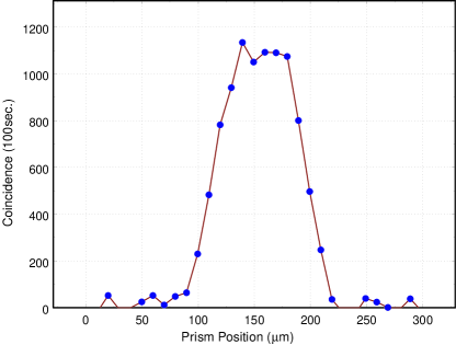
Since the input state (photon 1) and photon 2 should overlap inside the SFG crystals exactly, a prism is used to adjust the path-length of the input pulse [13]. is a dichroic mirror which reflects the 800nm photons while transmitting the 885nm ones. In order to be sure that the SFG process occurs with a single-photon input, we measured the coincidence counting rate between one of Alice’s detectors and Bob’s detector by moving the position of the prism. Fig. 5 shows a typical data curve of the measurement. It is clear that SFG only occurs when the input pulse (photon 1) and photon 2 (single-photon created by the SPDC process) overlap perfectly inside the SFG crystals [14].
Readers might have noticed that the efficiency in the teleportation measurement is a lot lower than the SFG demonstration. The reason why we get such a low coincidence counting rate in Figs.2 and 3 as compared to Fig.5 is that very small pinholes had to be placed in front of Alice’s detectors for the teleportation measurement to ensure good spatial mode overlap. The improvements of the SFG and the collection efficiencies while preserving good spatial mode overlap are now underway.
In summary, we have shown a proof-of-principle experimental demonstration of quantum teleportation with complete a Bell state measurement. The two main features lie at the heart of our scheme: (i) EPR-Bohm type quantum correlation and (ii) the BSM using nonlinear interactions. Single photon SFG is used as the BSM and the working principle is demonstrated by observing correlations between the joint measurement of Alice and Bob. In the current experiment, femtosecond laser pulses are used to prepare the input polarization state to reduce data collection time. Recent research on nonlinear optics at low light levels may enable high-efficiency SFG at single-photon level in the near future [15].
We would like to thank C.H. Bennett and M.H. Rubin for helpful discussions. This work was supported in part by the Office of Naval Research, ARDA, and the National Security Agency.
REFERENCES
- [1] A. Einstein, B. Podolsky, and N. Rosen, Phys. Rev. 47, 777 (1935).
- [2] C.H. Bennett et al., Phys. Rev. Lett. 70, 1895 (1993).
- [3] D. Bouwmeester et al., Nature 390, 575 (1997).
- [4] D. Boschi et al., Phys. Rev. Lett. 80, 1121 (1998).
- [5] A. Furusawa et al., Science 282, 706 (1998).
- [6] L. Vaidman and N. Yoran, Phys. Rev. A 59, 116 (1999); N. Lütkenhaus, J. Calsamiglia, and K.-A. Suominen, ibid. 59, 3295 (1999).
- [7] D.N. Klyshko, JETP 87, 639 (1998).
- [8] Note that any one of the four Bell states can be used for this purpose.
- [9] Complete BSM using SFG is also useful for other applications, see C.H. Bennett and S.J. Wiesner, Phys. Rev. Lett. 69, 2881 (1992).
- [10] In this experiment, the input state is a polarization state of a femtosecond laser pulse. Only one out of approximately photons, all in the same polarization state, in each laser pulse is actually “upconverted” in the SFG process. It can be easily shown that each photon has the polarization state of Eq.(1) by considering the correspondence principle. What is being teleported is the state or qubit associated with this photon. (Note, quantum teleportation does not teleport the “quantum” but rather, the state of the quantum). In principle, it does not prevent one to use a single-photon qubit as the input state in this experiment. Due to the low efficiency of SFG, one needs to wait a much longer time for teleportation to occur.
-
[11]
Y.-H. Kim, S.P. Kulik, and Y.H. Shih, Phys.
Rev. A 62, 011802(R), (2000);
quant-ph/0007067. - [12] Note that there are five different wavelengths which are tunable as long as the two phase matching conditions (for SPDC and for SFG) are satisfied. Also five independent relative phases which affect the output state can be varied.
- [13] 800nm input pulse and 400nm pump pulse (which pumps the SPDC crystals) are actually drawn from a single Ti:Sapphire laser to ensure that they have the same repetition period.
- [14] The efficiency of SFG (from the SPDC photons) is roughly estimated to be 0.11%. The SFG crystals used for the data shown in this paper are BBO’s with 2mm thickness.
- [15] S.E. Harris and L.V. Hau, Phys. Rev. Lett. 82, 4611 (1999).