Quantum computing via measurements only
A quantum computer promises efficient processing of certain computational tasks that are intractable with classical computer technology [1]. While basic principles of a quantum computer have been demonstrated in the laboratory [2], scalability of these systems to a large number of qubits [3], essential for practical applications such as the Shor algorithm, represents a formidable challenge. Most of the current experiments are designed to implement sequences of highly controlled interactions between selected particles (qubits), thereby following models of a quantum computer as a (sequential) network of quantum logic gates [4, 5]. Here we propose a different model of a scalable quantum computer. In our model, the entire resource for the quantum computation is provided initially in form of a specific entangled state (a so-called cluster state) of a large number of qubits. Information is then written onto the cluster, processed, and read out form the cluster by one-particle measurements only. The entangled state of the cluster thus serves as a universal substrate for any quantum computation. Cluster states can be created efficiently in any system with a quantum Ising-type interaction (at very low temperatures) between two-state particles in a lattice configuration.
We consider two and three-dimensional arrays of qubits that interact via an Ising-type next-neighbor interaction [6] described by a Hamiltonian [7] whose strength can be controlled externally. A possible realization of such a system is discussed below. A qubit at site can be in two states or , the eigenstates of the Pauli phase flip operator (). These two states form the computational basis. Each qubit can equally be in an arbitrary superposition state , . For our purpose, we initially prepare all qubits in the superposition , an eigenstate of the Pauli spin flip operator (). is then switched on for an appropriately chosen finite time interval, by which a unitary transformation is realized. Since acts uniformly on the lattice, entire clusters of neighboring particles become entangled in one single step. The quantum state , the state of a cluster () of neighboring qubits, which is thereby created provides in advance all entanglement that is involved in the subsequent quantum computation. It has been shown [6]
that the cluster state is characterized by a set of eigenvalue equations
| (1) |
where ngbh() specifies the sites of all qubits that interact with the qubit at site . The eigenvalues are determined by the distribution of the qubits on the lattice. The equations (1) are central for the proposed computation scheme. As an example, a measurement on an individual qubit of a cluster has a random outcome. On the other hand, (1) imply that any two qubits at sites can be projected into a Bell state by measuring a subset of the other qubits in the cluster. This property will be used to define quantum channels that allow us to propagate quantum information through a cluster.
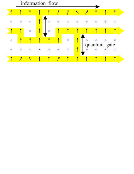
Here we will show that a cluster state can be used as a “substrate” on which any quantum circuit can be imprinted by one-qubit measurements. In Figure 1 this scheme is illustrated. For simplicity, we assume that in a certain region of the lattice each site is occupied by a qubit. This requirement is not essential as will be explained below (see d)). In the first step of the computation, a subset of qubits is measured in the basis of which effectively removes them. In Fig. 1 these qubits are denoted by “”. The state is thereby projected into a tensor product of measured particles on one side and an entangled network on the other side: . The entangled state is related to the cluster state on the network by a local unitary transformation which depends on the set of measurement results . still satisfies (1) for all and thus belongs to the same class of entangled states as the original cluster state . The measurement results enter in the signs in (1) for .
To process quantum information with this network, it suffices to measure its particles in a certain order and in a certain basis. Quantum information is thereby propagated horizontally through the cluster by measuring the qubits on the wire while qubits on vertical connections are used to realize two-bit quantum gates. The basis in which a certain qubit is measured depends in general on the results of the preceding measurements. The processing is finished once all qubits except a last one on each wire have been measured. At this point, the results of previous measurements determine in which basis these “output” qubits need to be measured for the final read-out.
In the following, we will show that any quantum logic circuit can be implemented on a cluster state. The purpose of this is twofold. First, it serves as an illustration of how to implement a particular quantum circuit in practice. Second, in showing that any quantum circuit can be implemented on a sufficiently large cluster state we demonstrate universality of the proposed scheme. For pedagogical reasons we will first explain a scheme with one essential modification with respect to the proposed scheme: before the entanglement operation , certain qubits are selected as input qubits and the input information is written onto them, while the remaining qubits are prepared in . This step weakens the scheme since it affects the character of the cluster state as a genuine resource. It can, however, be avoided (see e)). Points a) to c) are concerned with the basic elements of a quantum circuit, quantum gates and wires, point d) with the composition of gates to circuits.
a) Information propagation in a wire for qubits. A qubit can be teleported from one site of a cluster to any other site. In particular, consider a chain of an odd number of qubits 1 to prepared in the state and entangled by . The state of qubit 1, , can now be transfered to site by performing -measurements (bases ) at qubit sites with measurement outcomes . The resulting state is . The output state is related to the input state by a unitray transformation which depends on the outcomes of the -measurements at sites 1 to . A similar argument can be given for an even number of qubits. The effect of can be corrected for at the end of a computation as will be shown below (see d)). It is noteworthy that not all classical information gained by the -measurements needs to be stored to identify the transformation . Instead, is determined by the values of only two classical bits which are updated with every measurement.
b) An arbitrary rotation can be achieved in a chain of 5 qubits. Consider a rotation in its Euler representation . The qubits are initially in the state and entangled by . Then, qubits 1 to 4 are measured in the order implied by their numbering. Qubit 1 is measured in the direction of . (Measuring in the direction of means measuring the operator .) The directions for the remaining measurements are all in the --plane. Their angles with respect to the -axis are equal to the respective Euler angles ( for qubits 2,3,4) up to a sign . The signs of the angles depend on the results of previous measurements. The final state is then with . Again, the extra transformation can be read off from the measurement results and corrected at the end.
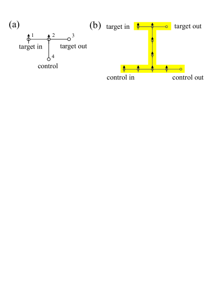
c) To perform the gate between a control qubit and a target qubit , four qubits, arranged as depicted Fig. 2a, are required. During the action of the gate, the target qubit is transfered from to . The following procedure has to be implemented. Be qubit 4 the control qubit. First, the state is prepared and then the entanglement operation performed. Second, of qubits 1 and 2 is measured. The measurement results correspond to projections of the qubits into or , . The quantum state created by this procedure is , where The input state is acted upon by the CNOT and successive - and -rotations , depending on the measurement results . These unwanted extra rotations can be accounted for as in a) and b). For practical purposes it is more convenient if the control qubit is, like the target qubit, transfered to another site during the action of the gate. When a CNOT is combined with other gates to form a quantum circuit it will be used in the form shown in Fig. 2b.
To explain the working principle of the CNOT-gate we will, for simplicity, refer to the minimal implementation with four qubits. The minimal CNOT can be viewed as a wire from qubit 1 to qubit 3 with an additional qubit, no. 4 attached. From the eigenvalue equations (1) it can now be derived that, if qubit 4 is in a eigenstate of then the value of determines whether a unit wire or a spin flip (modulo the same correction for both values of ) is being implemented. In other words, once of qubits 1 and 2 have been measured, the value of qubit 4 controls whether the target qubit is flipped or not.
d) Quantum circuits. The gates described – the CNOT and arbitrary one-qubit rotations – form a universal set [5]. In the implementation of a quantum circuit on a cluster state the site of every output qubit of a gate overlaps with the site of an input qubit of a subsequent gate. This way, the entire entanglement operation can be performed at the beginning. To see this, compare the following two strategies. Given a quantum circuit implemented on a network of qubits which is divided into two consecutive circuits. Circuit 1 is implemented on network and circuit 2 is implemented on network , and . There is an overlap which contains the sites of the output qubits of circuit 1 (these are identical to the sites of the input qubits of circuit 2). The sites of the readout qubits form a set . Strategy i) consists of following steps: (1) write input and entangle all qubits on ; (2) measure qubits to implement the circuit. Strategy ii) consists of (1) write input and entangle the qubits on ; (2) measure the qubits in . This implements the circuit on and writes the intermediate output to ; (3) entangle the qubits on ; (4) measure all qubits in . Step 3 and 4 implement the circuit 2 on . The measurements on commute with the entanglement operation restricted to , since they act on different subsets of particles. Therefore the two strategies are mathematically equivalent and yield the same results. It is therefore consistent to entangle in a single step at the beginning and perform all measurements afterwards.
Two further points should be addressed in connection with circuits. First, the randomness of the measurement results does not jeopardize the function of the circuit. Depending on the measurement results, extra rotations and act on the output qubit of every implemented gate. By use of the relations , and similar ones, these extra rotations can be pulled through the network to act upon the output state. There they can be accounted for by adjusting the measurement basis for the final readout. Rotations require some care. As stated above, changing the order of a spin flip and an arbitrary rotation reverses the sign of two Euler angles. This can be compensated for, but introduces a partial temporal ordering of the measurements on the whole cluster. Second, quantum circuits can also be implemented on irregular clusters. In that case, qubits are missing which are required for the standard implementation of the circuit. This can be compensated by a large flexibility in shape of the gates and wires. The components can be bent and stretched to fit to the cluster structure as long as the topology of the circuit implementation does not change.
e) Full scheme. It is important to note that the step of writing the input information onto the qubits before the cluster is entangled, was introduced only for pedagogical reasons. For illustration of this point consider a chain of 5 qubits in the state . Clearly, there is no local information on any of the qubits. However, by measuring qubits 1 to 4 along suitable directions, the qubit 5 can be projected into any desired state (modulo ). What is used here is the knowledge that the resource has been prepared with qubit 1 in the state before the entanglement operation. By the four measurements, this qubit is rotated as described in b). In a similar manner any desired input state can be prepared if the rotations are replaced by a circuit preceding the proper circuit for computation. In summary, no input information needs to be written to the qubits before they are entangled. Cluster states are thus a genuine resource for quantum computation via measurements only.
A possible implementation of such a quantum computer uses neutral atoms stored in periodic micropotentials [8, 9, 10] where Ising-type interactions can be realized by controlled collisions between atoms in neighboring potential wells [9, 11]. This system combines small decoherence rates with a high scalability. The question of scalability is, in fact, closely linked to the percolation phenomenon. For a site occupation probability above the percolation threshold, there exists a cluster which is bounded in size only by the trap dimensions. For optical lattices in three dimensions, single-atom site occupation with a filling factor of 0.44 has been reported [12] which is significantly above the percolation treshold of 0.31 [13]. As in other proposed implementations for quantum computing, the addressability of single qubits in the lattice is however still a problem. (For recent progress see Ref. [14]).
For a cluster of a given finite size, the number of computational steps may be too large to fit on the cluster. In this case, the computation can be split into several parts, for each of which there is sufficient space on the cluster. The modified procedure consists then of repeatedly (re)entangling the cluster and imprinting the actual part of the circuit until the whole calculation is performed. In this sense, cluster states can be recycled. This procedure has also the virtue that qubits involved in the later part of a calculation need not be protected from decoherence for a long time while the calculation is still being performed at a remote place of the cluster. Standard error-correction techniques [15, 16] may then be used on each part of the circuit to stabilize the computation against decoherence.
In conclusion, we have described a new scheme of quantum computation that consists entirely of one-qubit measurements on a particular class of entangled states, the cluster states. The measurements are used to imprint a quantum circuit on the state, thereby destroying its entanglement at the same time. Cluster states are thus one-way quantum computers and the measurements form the program.
REFERENCES
- [1] Bennett, C. H. & DiVincenzo, D. P. Quantum information and computation. Nature 404, 247–255 (2000).
- [2] See Ref. [1] for a recent review.
- [3] Cirac, J. I.& Zoller, P. A scalable quantum computer with ions in arrays of microtraps. Nature 404, 579–581 (2000).
- [4] Deutsch, D. Quantum computational networks. Proc. R. Soc. London 425, 73-90 (1989).
- [5] Barenco, A. et al. Elementary gates for quantum computation. Phys. Rev. A 52, 3457–3467 (1995).
- [6] Briegel, H.-J. & Raussendorf, R. Persistent entanglement in arrays of interacting particles. Pre-print quant-ph/0004051 at xxx.lanl.gov (2000).
- [7] The second Hamiltonian is of the standard Ising form. The symbol means that the states generated from a given initial state, under the action of these Hamiltonians, are identical up to a local rotation on certain qubits. We use the first Hamiltonian to make the computational scheme more transparent. The conclusions drawn in the paper are, however, the same for both Hamiltonians.
- [8] Brennen, G. K., Caves, C. M., Jessen, P. S. & Deutsch, I. H. Quantum Logic Gates in Optical Lattices. Phys. Rev. Lett. 82, 1060-1063 (1999).
- [9] Jaksch, D., Briegel, H.-J., Cirac, J. I., Gardiner, C. W. & Zoller, P. Entanglement of Atoms via Cold Controlled Collisions. Phys. Rev. Lett. 82, 1975-1978 (1999).
- [10] Calarco, T., Jaksch, D., Cirac, J. I. & Zoller, P. Quantum Gates with neutral atoms: Controlling collisional interactions in time dependent traps. Phys. Rev. A 61, 022304 (2000).
- [11] H.-J. Briegel, Calarco, T., Jaksch, D., Cirac, J. I. & Zoller, P. Quantum computing with neutral atoms. J. Mod. Opt. 47, 415-451 (2000).
- [12] DePue, M. T., McCormick, C., Winoto, S. L., Oliver, S. & Weiss, D. W. Unity Occupation of Sites in a 3D Optical Lattice, Phys. Rev. Lett. 82, 2262-2265 (1999).
- [13] Ziman, J. M. Models of Disorder. Cambridge University Press, 1979.
- [14] Scheunemann, R., Cataliotti, F. S., Hänsch, T. W, & Weitz M. Resolving and addressing atoms in individual sites of a CO2-laser optical lattice. Accepted by Phys. Rev. A.
- [15] Calderbank, A. & Shor, P. W. Good quantum error correcting codes exist. Phys. Rev. A 54, 1098 (1996).
- [16] Steane, A. Error Correcting Codes in Quantum Theory. Phys. Rev. Lett. 77, 793 (1996).