Bell State Preparation using Pulsed Non-Degenerate Two-Photon Entanglement
Abstract
We report a novel Bell state preparation experiment. High-purity Bell states are prepared by using femtosecond pulse pumped nondegenerate collinear spontaneous parametric down-conversion. The use of femtosecond pump pulse does not result in reduction of quantum interference visibility in our scheme in which post-selection of amplitudes and other traditional mechanisms, such as, using thin nonlinear crystals or narrow-band spectral filters are not used. Another distinct feature of this scheme is that the pump, the signal, and the idler wavelengths are all distinguishable, which is very useful for quantum communications.
pacs:
PACS Number: 03.67.Hk, 03.65.Bz, 42.50.DvPreparation and measurement of the Bell states are two important issues in modern quantum optics, especially for quantum communications, quantum teleportation, etc [2]. For photons, such states can be realized by using the entangled photon pairs generated in spontaneous parametric down-conversion (SPDC). By making appropriate local operations on the SPDC photon pairs, one can prepare all four Bell states.
The polarization Bell states, for photons, can be written as
| (1) | |||||
| (2) |
where the subscripts 1 and 2 refer to two different photons, photon 1 and photon 2, respectively, and they can be arbitrarily far apart from each other. and form the orthogonal basis for the polarization states of a photon, for example, it can be horizontal ( ) and vertical () polarization state, as well as and , respectively. This means that the quantum interference should be independent of the choice of the bases.
Such an experiment was first performed by Shih and Alley in which non-collinear type-I SPDC and a beamsplitter were used to prepare a Bell state [3], but it is very difficult to align such a system. Collinear type-II SPDC is thus developed [4]. There is, however, a common problem: the entangled photon pairs have 50% chances of leaving at the same output ports of the beamsplitter. Therefore, the state prepared after the beamsplitter may not be considered as a Bell state without amplitude post-selection [5]. Only when one considers the coincidence contributing terms by throwing away two out of four amplitudes (post-selection of 50% of the amplitudes), the state is then said to be a Bell state. This problem is later solved by using non-collinear type-II SPDC or using two non-collinear type-I SPDC [6].
In the cw pumped SPDC, entangled photon pairs occur randomly since the process is “spontaneous”, so whereabouts of the photon pair is completely uncertain within the coherence length of the pump laser beam. This huge time uncertainty makes it difficult for applications such as generation of multi-photon entangled state, quantum teleportation, etc, as interactions between entangled photon pairs generated from different sources are required. This difficulty was thought to be solved by using a femtosecond pulse laser as a pump. Unfortunately, femtosecond pulse pumped type-II SPDC shows poor quantum interference visibility due to the very different (compared to the cw case) behavior of the two-photon effective wave-function [7]. One has to utilize special experimental schemes to achieve complete overlap of the two-photon amplitudes. Traditionally, the following methods were used to restore the quantum interference visibility in femtosecond pulse pumped type-II SPDC: (i) use a thin nonlinear crystal (m) [9] or (ii) use narrow-band spectral filters in front of detectors [7, 8]. Both methods, however, reduce the available flux of the entangled photon pair significantly [10] and cannot achieve complete overlap of the wave-functions in principle [7].
The first attempt to achieve high-visibility quantum interference in femtosecond pulse pumped type-II SPDC without using narrowband filters and a thin crystal was reported in Ref.[11]. The observed visibility, however, was rather low and keeping the phase coherence over a long term would be very difficult since a Michelson interferometer is used. Also, such a scheme cannot be used to prepare a Bell state. Recently, we reported a high-visibility quantum interference experiment in which photon pairs are entangled both in polarization and space-time using femtosecond pulse pumped type-I SPDC [12]. However, it cannot be considered as a true Bell state preparation since post-selecting 50% of the amplitudes was still necessary.
In this Letter, we report a Bell state preparation experiment in which we effectively eliminate any post-selection in femtosecond pulse pumped SPDC for the first time. Other features in our scheme include: (i) collinear SPDC makes the alignment much easier, (ii) Alice and Bob shares photons of different frequencies entangled in both space-time and polarization, (iii) phase coherence is automatically kept and the visibility as high as 92% is observed, (iv) thick crystals can be used to increase the intensity (without losing the visibility), and (v) the spectral bandwidth is reduced significantly by the use of nondegenerate SPDC. These features make our scheme a good source of Bell states for quantum information experiments.
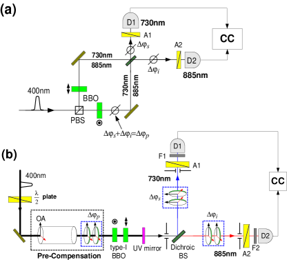
The basic idea of the experiment is illustrated in Fig.1(a). A polarized femtosecond laser pulse (central wavelength nm and pulse duration fsec.) enters the Mach-Zehnder interferometer (MZI) which contains a type-I nonlinear crystal in each arm. One crystal has its optic axis oriented vertically () and another horizontally (). Polarizing beamsplitter (PBS) splits the polarized pump pulse into the vertical and horizontal polarized pulses propagating along different arms of the MZI. Then non-degenerate collinear type-I SPDC occurs, with equal probability, at each crystal (signal wavelength nm and idler wavelength nm) and they are mixed at the dichroic beamsplitter which directs 730nm photons to detector and 885nm to detector . In the simplified single mode approximation, the quantum state generated from the vertically oriented crystal () is and from the horizontally oriented one () is . and represent horizontal and vertical polarization state of a single photon respectively. Subscripts 730 and 885 refer to the wavelengths 730nm and 885nm, respectively. When the MZI is balanced, the quantum state after the MZI is (without throwing away any amplitudes)
| (3) |
where is the relative phase between the two amplitudes and it can easily be varied by scanning one of the mirror of the MZI.
The coincidence counting rate () is calculated as [13, 14],
| (4) |
where and . where is the time at which detector fires and is the optical path length from the surface of the crystal to the detector . is the amplitude of the biphoton as explicitly calculated in Ref.[7].
For the scheme shown in Fig.1(a), is the sum of the two amplitudes originated from the crystal in each arm of the MZI:
| (5) |
where the subscripts and refer to the crystal from which the amplitudes are created. The delay introduced in one arm modifies the amplitude and determines the additional phase shift for the biphoton amplitudes , where , the central frequency (wavelength) of the pump, and the spatial delay. Due to the energy conservation and negligibly small dispersion of the air, the phase shift depends only on the pump wavelength although the delay is introduced to the SPDC field [12, 15]. If the crystals are the same and the pump fields in different arms of the MZI are identical,
| (6) |
The coincidence counting rate is then calculated to be
| (7) |
where in this experiment [16]. Note that the angles of the analyzers and are assumed to be . From Eq.(7), we expect that the coincidence counting rate will be modulated in the pump central wavelength when is varied.
There are also two more ways to vary the phases of interference by introducing relative delays (using a piece of birefringent material, such as a quartz plate) after the output beamsplitter, i.e., in the signal () and/or in the idler () channels. Therefore we obtain
| (8) |
where , , and refer to the relative phases of the pump, the idler, and the signal, respectively.
As we have shown so far, one can eliminate the possibility of the entangled photon pairs leaving at the same output ports of the beamsplitter by employing non-degenerate two-photon entanglement. In this scheme, high-visibility quantum interference can be achieved independent of the crystal thickness and the spectral filter bandwidths even with femtosecond pulse pump.
In practice, however, one would not like to use a MZI in the experimental setup due to stability related issues. Therefore, we use a collinear scheme where two type-I BBO crystals are placed collinearly in the pump beam path, see Fig1(b). Two type-I BBO crystals with thickness 3.4mm each (the first one is oriented horizontally and the second one is oriented vertically) are then pumped by a polarized pump pulse. As described before, the quantum state resulting from the first BBO is and that from the second BBO is . Since both crystals are pumped equally, the two amplitudes are equally probable. Due to the dispersion, however, from the first BBO () and from the second BBO () are distinguishable in time. To make and indistinguishable in time, one needs to compensate the delay experienced by the SPDC photon pairs at each crystal. This compensation can be made by using a properly oriented quartz rod. If the compensation is made properly, either before or after the down-conversion non-linear crystals, one will observe high-visibility quantum interference without any spectral post-selection.
In the collinear scheme, having a perfect temporal compensation is difficult when the signal wavelength differs very much from the idler wavelength. This is because the signal-idler photon pairs created from the first BBO () experience different dispersion when they pass through the second BBO (). (The MZI scheme does not have this disadvantage). In this experiment, for the wavelengths we are interested in, the temporal separation is rather small and it does not affect the interference visibility. To prevent further dispersion effects, the compensation is made before the BBO crystals. The compensator consists of a quartz rod and two quartz plates whose optic axes are oriented vertically, see Ref.[12], and it imposes roughly 1.5psec required delay between the - and -polarized 400nm pump pulse which is mainly determined by the thickness of the BBO crystals. By tilting the two quartz plates in the opposite directions, the phase delay can be varied to prepare a Bell state. After the two BBO crystals, the remaining UV radiation is blocked by a UV reflecting mirror and the collinear SPDC is selected by a diaphragm. Then a dichroic beamsplitter is used to reflect the signal (730nm) to and to transmit the idler (885nm) to . Two quartz plates are inserted in each beam path to vary the relative phase of the signal or the idler independently. The detector package consists of a single-photon counting module, an interference filter which is used to cut the pump noise [18], and a polarization analyzer.
To demonstrate the effectiveness of this scheme, we first study the space-time interference as a function of by setting , where and are the angles of the analyzers and (measured from the vertical direction). According to Eq.(8), one should observe a pump wavelength modulation in the coincidence counting rate. Note that and are fixed. The observed modulation period is 400nm, see Fig.2(a), which agrees with the theory.
To prepare () state, identified by constructive (destructive) interference, one just needs to set () which can be done by tilting the quartz plates so that the space-time interference fringe is at the maximum (minimum). Note that and Bell states can also be easily prepared by introducing a plate in one output port of the dichroic beamsplitter.
We have also experimentally demonstrated the polarization interference for and . For , the coincidence counting rate is calculated to be
| (9) |
This means that one should observe high-visibility modulation in polarization correlation measurement for arbitrary values of and . To confirm this experimentally, we first set and varied . High-visibility polarization correlation is observed, see Fig.2(b). We then repeated this measurement for many other values of and observed that the visibility remained the same. This confirms Eq.(9). In other words, we have successfully prepared polarization Bell states from femtosecond pulse-pumped SPDC without amplitude and spectral post-selection.
Unlike the usual degenerate two-photon sources, this source has one distinctive feature: one can vary three different phases independently which is very useful for quantum communications. To demonstrate this interesting feature, we observe the space-time interference by varying the relative phases of the signal () and the idler () independently. In these measurements, and are set at . The effect of is already demonstrated in Fig.2(a). When the signal phase is varied, see Fig.3(a), the signal wavelength (730nm) modulation is observed in coincidence rate, while varying the idler phase , see Fig.3(b), the idler wavelength (885nm) modulation is observed. Fig. 2(a), Fig.3(a), and Fig.3(b) clearly demonstrate Eq.(8).
Finally, we tested the condition by varying the signal phase and the idler phase at the same time. The quartz plates in both the signal and the idler paths are tilted at the same time with equal angles. To see whether the data agrees with the theory, total phases accumulated in both beam path are calculated from the tilt angle, i.e., . As evidenced from Fig.3(c), the data agrees well with Eq.(8).
In summary, we have demonstrated a novel scheme to prepare pulsed entangled photon pairs from which all four Bell states can be easily obtained. Amplitude and spectral post-selection are not necessary. Note also that non-maximally entangled states can be prepared by changing the relative intensities of the pump beams. The visibility and the photon flux is greatly enhanced by this method although a femtosecond pulse laser is used as a pump. The signal, the idler, and the pump phases can be varied independently with different modulation frequency which is very useful for quantum communications.
We would like to thank M.H. Rubin for helpful discussions. This research was supported, in part, by the Office of Naval Research, ARDA and the National Security Agency. S.P.K. also thanks the Russian Fund for Fundamental Research Grant No. 99-02-16419 for partially supporting his visit to UMBC.
REFERENCES
- [1]
- [2] S.L. Braunstein, A. Mann, and M. Revzen, Phys. Rev. Lett. 68, 3259 (1992); C.H. Bennett et al., Phys. Rev. Lett. 70, 1895 (1993); A.K. Ekert, Phys. Rev. Lett. 67, 661 (1991).
- [3] C.O. Alley and Y.H. Shih, Proc. of 2nd Int. Symp. Foundations of Quantum Mechanics, ed. M. Namiki (Physical Society of Japan, Tokyo) (1987); Y.H. Shih and C.O. Alley, Phys. Rev. Lett. 61, 2921 (1988).
- [4] T.E. Kiess et al. Phys. Rev. Lett. 71, 3893 (1993).
- [5] L. De Caro and A. Garuccio, Phys. Rev. A 50, R2803 (1994).
- [6] P.G. Kwiat et al. Phys. Rev. Lett. 75, 4337 (1995); P.G. Kwiat et al., Phys. Rev. A 60, R773 (1999).
- [7] T.E. Keller and M.H. Rubin, Phys. Rev. A 56, 1627 (1997).
- [8] W.P. Grice and I.A. Walmsley, Phys. Rev. A 56, 1627 (1997); G. Di Guiseppe et al. ibid. 56, R21 (1997); W.P. Grice et al. ibid. 57, R2289 (1998).
- [9] A.V. Sergienko et al., Phys. Rev. A 60, R2622 (1999).
-
[10]
Recently Atatüre et al. [Phys. Rev.
Lett. 84, 618 (2000)] claimed that one can recover
high-visibility quantum interference in pulse pumped type-II SPDC
from a thick crystal without spectral post-selection (by using
narrow-band spectral filters). The theory as well as the
interpretation of the experimental data presented their work are,
however, shown to be in error, see Y.-H. Kim et al,
quant-ph/0006003. - [11] D. Branning et al., Phys. Rev. Lett. 83, 955 (1999).
- [12] Y.-H. Kim, S.P. Kulik, and Y.H. Shih, Phys. Rev. A 62, 011802(R) (2000).
- [13] R.J. Glauber, Phys. Rev. Lett. 10, 84 (1963); Phys. Rev. 130, 2529 (1963).
- [14] M.H. Rubin et al., Phys. Rev. A 50, 5122 (1994).
- [15] A.V. Burlakov et al., JETP Letters 69, 831 (1999).
- [16] The visibility factor is in general a function of , , the group velocities of the ordinary ray, the pump pulse duration, and the delay . Note that is not a function of bandwidths of the spectral filters. One can also prepare a Bell state using two type-II SPDC. Eq.(8) still remains valid, but the function has different width and shape. We will discuss the details of the theory and experiments of this scheme by using type-I and type-II SPDC in [17].
- [17] Y.-H. Kim, M.V. Chekhova, S.P. Kulik, M.H. Rubin, and Y.H. Shih, manuscript in preparation.
- [18] The bandwidth of the spectral filter is 10nm at full width half maximum. This is comparable to the spectrum bandwidth of type-I nondegenerate SPDC which is 13nm for the crystals used in the experiment.