Mechanochemical coupling of kinesin studied with the neck linker swing model
Abstract
We have proposed the neck linker swing model to investigate the mechanism of mechanochemical coupling of kinesin. The Michaelis-Menten-like curve for velocity vs ATP concentration at different loads has been obtained, which is in agreement with experiments. We have predicted that Michaelis constant doesn’t increase monotonically and an elastic instability will happen with increasing of applied force.
pacs:
87.16.NnI introduction
Kinesin is a molecular motor that transports organelles and membrane-bound vesicles along a microtubule in various cells val99 ; hir98 . It takes hundreds of steps (the size of tubulin heterodimers composed of and subunits)blo90 ; svo93 ; how96 before detachment and the run length is longer than blo90 ; svo93 ; how96 ; kaw00 . This is why kinesin is called a processive motor.
Conventional kinesin (hereafter called ‘kinesin’) is a dimer consisting of two identical kD chains, commonly known as heavy chains. Each heavy chain contains a N-terminal globular head domain, a stalk region which is responsible for heavy chain dimerization, a tether that joins the head and stalk, and a C-terminal fan-shaped tail domain which usually binds cargo for transporting in living cell or bead for applying force in single molecule manipulated experiments hir99 ; hir89 . The head domain is a highly conserved region for different members of the kinesin superfamily and contains two binding sites. One binds to microtubule and the other to nucleotides. Two heads alternately hydrolyze one molecular of ATP for each stepval99 ; hir98 ; blo90 ; svo93 ; how96 ; kaw00 ; how89 ; hac95 ; hua97 ; sch97 ; coy99 . Sometimes, the 8-nm step can be resolved into fast and slow substeps, each corresponding to a displacement of nis01 . The tether is a -amino-acid segment. It becomes immobilized and extended towards the forward direction when its head binds microtubule and ATP, and reverts to a more mobile conformation when phosphate is released after ATP hydrolysisric99 . If the tether is replaced by a random sequence of amino acidscas00 or if it is cross-linked to nucleotides sitetom00 , the kinesin will lose the capability of stepping. Therefore, the conformational change of tether seems to be necessary for kinesin to stepric99 .
The motility of kinesin can be explained by a “hand over hand” modelkas03 ; asb03 ; yil04 ; sch04 . The two heads alternately repeat single- and double-headed binding with microtubule. A simplified binding mode has been proposedkaw01 . For single-headed binding, the attached head either binds ATP or is empty, whilst the detached head binds ADP. For double-headed binding, the forward head is empty, whilst the rear head binds either ATP or ADPP.
Kinesin works in a cyclic fashion for several intermediate states. The Michaelis-Menten relation for the rate of ATP hydrolysis is still a basic lawhow89 ; svo93 ; hac95 ; gil95 ; gil98 ; moy98 ; shu04 . The average stepping velocity, however, also has been experimentally found obeying the Michaelis-Menten law for a range loadsvis99 , which means the mechanochemical coupling is tight, i.e., kinesin hydrolyzes one molecular of ATP for each stepsch97 . With increasing of the applied force, the saturating velocity decreases as expected, however, Michaelis constant surprisingly increasesvis99 . The role of force in the reaction kinetics can be used to investigate the mechanism of mechanochemical coupling.
In this paper, we present a neck linker swing model to investigate the mechanism of mechanochemical coupling of kinesin. We will discuss the effect of applied force on the reaction kinetics and the elastic instability of the complex composed of neck linker and attached head.
II neck linker swing model
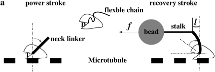
When a head attaches microtubule, its tether becomes a rigid rod that can be bent by an applied force, and we call this tether as a neck linker. Otherwise, we call the tether as a flexible chain if its head is detachedric99 .
An idealized scheme of the relations among nucleotides, microtubule and the tether’s conformation is shown in Figure 1aric99 ; val00 ; sos01 ; nel04 . For attached head, if its catalytic cleft is empty, the neck linker tends to be perpendicular to microtubule. ATP binding will change the catalytic cleft’s conformation. The allosteric interaction between two binding sites in the attached head will trigger neck linker to swing to the forward directionric99 .
The neck linker swing model consists of two chemical transitions ( and ) and two mechanical substeps ( and ) as shown in Figure 1b. This model is consistent with the widely accepted model for the kinetic mechanism of kinesincro04 . We just keep their main processes and rearrange them into steps in our model. This approximation is reasonable for the case that ADP concentration is low.
In this model, the mechanochemical cycle of kinesin includes four steps: ATP binding; power stroke; ADP releasing + ATP hydrolysis and recovery stroke.

II.1 chemical transition 1: ATP binding
When a head strongly attaches to the microtubule and waits for ATP binding, the neck linker will be bent by the applied force to the backward direction with displacement as shown in Figure 1a. The bending energy and the force in the case of slight bending, where is the bending rigidity.
The attached head will finally bear the bending energy and the energy barrier for ATP binding will increase. So ATP binding rate can be written as:
| (1) |
where is ATP binding constant without applied force, is Boltzmann constant, and is absolute temperature. This relationship holds whether [ATP](ATP concentration) is high or low. During attached head is waiting for ATP binding, the free head can’t reach any binding site on the track because the end-to-end distance of the flexible chain is not long enough. These sites are separated by a fixed distance () along the rigid microtubule.
II.2 mechanical substep 1: power stroke
Once the attached head binds an ATP molecule, neck linker will move to the new equilibrium position, and the free head and bead will be thrown forward. A power stroke occurs. We assume the motion of bead, by which optical tweezer can applies force on motor, is overdamped, the average velocity is
| (2) |
where is the viscous coefficient, and are average forces generated from ATP binding and releasing of the bending energy respectively, that is, . The power stroke rate then is
| (3) |
is the energy that power stroke outputs, and originates from the catalytic cleft’s conformational change induced by ATP bindingric99 .
II.3 chemical transition 2: detached head’s ADP releasing and attached head’s ATP hydrolysis
With starting of the power stroke, the random motion of the free head will be biased to the forward direction and the flexible chain will be stretched due to neck linker’s throwing and the interaction from the nearest -tubulin monomer, which greatly increases the probability that the free head reaches the next binding site on the track. It first bind weakly, eventually, releases its ADP and attaches strongly to the track. The stretched chain will shrink and transform into a rigid rod, which helps the rear head to split the bound ATP, and one of products, phosphate will be releasedric99 ; kaw01 ; nel04 . This reaction weakens the binding of the rear head with the microtubule and leads it to detach from the track with ADPric99 ; kaw01 ; nel04 . We assume the rate of the process from the end of power stroke to the detaching of rear head, , is independent of applied force.
II.4 mechanical substep 2: recovery stroke
The tether linked the forward head now becomes the neck linkerric99 ; kaw01 ; nel04 , and will swing to the mechanical equilibrium position. A recovery stroke occurs. Similar with the power stroke, the rate of this step
| (4) |
where originates from the catalytic cleft’s conformational change induced by ADP releasing, which is conformationally the recovery process of ATP binding.
The cycle is now ready to repeat, the difference is that roles of these two partner heads have exchanged. The kinesin dimer has hydrolyzed one ATP and moved forward with two substepsric99 ; val00 ; sos01 ; nel04 . Although there are more than two chemical transitions as above, all other chemical processes are rapid rate transitions (randomness shows that there are only two to three rate-limiting transitionsvis99 ; blo03 ; sch95 ). We lump all other chemical transitions into .
III fitting and results
From the time series shown in Figure1b, the average time to complete a single enzymatic cycle, , can be computed convenientlysch95 ; sun01 . The average velocity of kinesin moving along microtubule is
| (5) |
with
| (6) | |||||
| (7) |
where and are saturating velocity and Michaelis constant respectively. Obviously, the average velocity obeys the Michaelis-Menten law as observedvis99 .
In our model, and are independent of ATP concentration. We define the efficiency of mechanochemical coupling of kinesin as and assume it is a constant, where is the free energy excess in one molecule ATP hydrolysis. It must be noted that defined here is different from the efficiency of motor. We assume kinesin has adjusted and to achieve optimal kinetic velocity in evolution. From Eq.(3) and Eq.(4), we yield (), which is reasonable with the fact that the catalytic cleft’s conformational change induced by ADP releasing is conformationally the recovery process of that induced by ATP binding. For simplicity, we introduce the rate of power (or recovery) stroke without load, .
According to Eqs.(3) and (4), the power stroke rate decreases with increasing of applied force , whilst the recovery stroke rate increases as shown in Figure2(d). At a critical applied force, becomes zero. We call this critical force as stall force. It can be derived as
| (8) |
If applied force is larger than the stall force, the force induced by conformation change can’t overcome it to push the kinesin forward along the microtubule.
For the case of slight bending of neck linker, Eq.(8) can be rewritten as with under physiological conditionsstr95 , which is in agreement with the experimental datavis99 . It must be noted that stall force in our model is independent of ATP concentration. We can rewrite Eq.(6) and Eq.(7) as
| (9) | |||
| (10) |
and use them to fit the measured data of and at different loadsvis99 , where , and . The fitted values of , , , and are listed in table 1, and the two fitted curves, and , are shown in Figure 2(a).
| (pN) | (pNnm-1) | (Ms-1) | (s-1) | (pNs/nm) |
| 6.50 | 1.88 | 1.33 | 120 | 1.45 |
The fitted stall force is consistent with measured valuevis99 . The total energy outputted in one cycle, , is less than , which demonstrated again that the fitted values are reasonable. The efficiency of mechanochemical coupling of kinesin, , is about 93%. However, the efficiency of motor, , is about 65%, which is in agreement with experiments.
It is the motion of a silica bead that is measured in experimentvis99 . The radius of the bead, , is . The viscousity of water at room temperature, , is about . The Stokes drag coefficient of the bead can be estimated by , and is about . The fitted viscous coefficient of bead in our model, thus, is comparable with the Stokes drag coefficient for a sphere in diameter at room temperature.
The widely accepted model for the kinetic mechanism of kinesincro04 has proposed that the ATP binding rate is about and the rate from free head’s ADP releasing to attached head’s detaching can be estimated about . In our model, ATP dissociating rate isn’t taken into account, this is why is slightly less than the proposed value. also approaches the estimated value.
IV discussion
IV.1 no longer increases monotonically with load
Although the recovery stroke will go faster and faster with increasing of applied force, the power stroke will spend more and more time and finally stalls at the stall force, which leads to the concave down of saturating velocity. With low applied force, Michaelis constant will nearly increase exponentially because increases faster than decreases. With high force, power stroke becomes the rate-limiting step for the single enzymatic cycle, so, will fall fast as shown in Figure2(a). Michaelis constant no longer increases monotonically with load. The big error bar at high force implies that this prediction is possible.

IV.2 neck linker’s bending
Actually, the neck linker’s bending has been unconsciously revealed in experimentkaw01 . With an applied force moving toward the end of microtubule, a simply elastic model can fit all extension of kinesin-microtubule complex for double-headed attaching. But the force-extension relation in Figure2(c) can’t be fitted by a same simply elastic model for all extension for single-headed attaching. With our neck linker swing model, we can image there are three distinctive regions of force. If the force is low, the “Extension” is mainly contributed by neck linker bending. We compare the relation to the experimental force-extension datakaw01 in Figure 2(c). It is very surprising that our model is in agreement with experiment very well. With the increasing of applied force, a phenomenon of elastic instabilitylan86 will inevitably happen to the complex composed of neck linker and attached head. This is why the extension rapidly increases while the “applied force” falls fast as the measured data in Figure 2(c). After reaching the new mechanical equilibrium, the complex will further extend with increasing of applied force, and its force-extension relation can be fitted by a simply elastic model again.
IV.3 velocity versus applied force at saturating and limiting ATP concentration
With these reasonable fitted parameters, we can use Eq.(5) directly to compute the dependence of the velocity on load at saturating and limiting ATP concentrations. As shown in Figure 2(b), the theoretical velocity-force relation is in good agreement to experimental datavis99 . It is clear that there are three distinctive regimes of applied force: (1) If the load is low, chemical transition 2, the process from free head’s ADP releasing to attached head’s ATP hydrolysis, , is the rate-limiting transition at saturating [ATP] and , which is consistent with what is known about the biochemistry of kinesinhac88 ; gil94 , while ATP binding is the rate-limiting transition at low [ATP] and with . (2) If load is high, kinesin will stall at the same force as discussed in section III whether ATP concentration is high or low. (3) If applied force is moderate, the velocity-force curves display different shapes at low and saturating ATP concentration respectively. At very low ATP concentration, the velocity decreases exponentially as and looks like linear with load because ATP binding is the rate-limiting step. At saturating [ATP], the velocity is concave down with load as discussed in section IV.1.
IV.4 two mechanical substeps
The two mechanical substeps in this model are contributed by the two heads respectively. The recovery stroke is always a rapid rate step which corresponds to the observed fast substepnis01 . If a moderate load such as acts on the bead and ATP concentration is maintained at , the two chemical transitions have the same rate as shown in Figure2(d). The time spent in ATP binding equals that spent in chemical transition 2. Theoretically, slow substep and fast substep can be detected directly by single molecular manipulated techniques such as optical tweezers. The different load-dependence of these substeps’ rate may be revealed in the future experiment.
V conclusion
We proposed the neck linker swing model which divides the single enzymatic cycle into two chemical transitions and two mechanical substeps. Each chemical transition will induce the conformational change in the catalytic cleft and generate a corresponded mechanical stroke. The model can be used to explain the observed substepsnis01 . The different load-dependence of these two strokes’ rate may be revealed in the future experiment. We have investigated the mechanism of mechanochemical coupling of kinesin by the influence of applied force on the bending of neck linker. When attached head is waiting for ATP binding, the neck linker is bent by the applied force. The attached head bears the neck linker’s bending energy and the energy barrier for ATP binding increases. This is why Michaelis constant increases with applied force. Our theoretical analysis of average velocity of motor in Eq.(5) also obeys Michaelis-Menten law and has been used to fit the observed saturating velocity and Michaelis constant at different loadsvis99 . The fitted values of chemical reaction rates are in agreement with those in the widely accepted modelcro04 , and the fitted viscous coefficient of bead is also comparable with the Stokes drag coefficient. The stall force is independent of ATP concentration and its fitted value is consistent with the observed data in experimentvis99 . The fitted bending rigidity of neck linker can be used to explain the relation of force-extension in experiment at low forcekaw01 . With these reasonable fitted parameters, we can directly use Eq.(5) to describe the relation between the average velocity and load at different ATP concentrations, which is in good agreement to experimental datavis99 as shown in Figure 2(b). In addition, we have predicted Michaelis constant doesn’t increase monotonically and an elastic instability will happen to the complex composed of neck linker and attached head with increasing of applied force.
Acknowledgements
We acknowledge useful discussions with Ou-Yang Zhong-can and Ming Li. This work was supported by Special Fund for Theoretical Physics of Postdoctor and National Science Foundation of China.
References
- (1) T.Kreis and R.D.Vale , Guidebook to the Cytoskeletal and Motor Proteins, (Oxford Univ. Press, Oxford, ed. 2, 1999) pp.398-402
- (2) N.Hirokawa, Science, 279, 519 (1998)
- (3) S.M.Block, L.S.B.Goldstein and B.J.Schnapp, Nature, 348, 348 (1990)
- (4) K.Svoboda et al., Nature 365, 721 (1993)
- (5) J.Howard, Annu. Rev. Physiol. 58, 703 (1996)
- (6) K.Kawaguchi and S.Ishiwata, Biochem. Biophys. Res. Commun. 272, 895 (2000)
- (7) K.Hirose, L.A.Amos, Cell. Mol. Life Sci. 56, 184(1999)
- (8) N.Hirokawa et al., Cell 56, 867(1989)
- (9) J.Howard, A.J.Hudspeth and R.D.Vale, Nature 342, 154 (1989)
- (10) D.D.Hackney, Nature 377, 448 (1995)
- (11) W.Hua et al., Nature 388, 390 (1997)
- (12) M.J.Schnitzer and S.M.Block, Nature 388, 386 (1997)
- (13) D.L.Coy, M.Wagenbach and J.Howard, J. Biol. Chem. 274, 3667 (1999)
- (14) M.Nishiyama et al., Nat. Cell Biol., 3, 425 (2001)
- (15) S.Rice et al., Nature 402, 778 (1999)
- (16) R.B.Case et al., Curr. Biol., 10, 157 (2000)
- (17) M.Tomishige and R.D.Vale, J. Cell. Biol. 151, 1081 (2000)
- (18) K.Kasedal, H.Higuchi and K.Hirosel, Nat. Cell Biol., 5, 1079 (2003)
- (19) C.L.Asbury, A.N.Fehr and S.M.Block, Science, 302, 2130 (2003)
- (20) A.Yildiz et al., Science, 303, 676 (2004)
- (21) W.R.Schief et al., PNAS, 101, 1183 (2004)
- (22) K.Kawaguchi and S.Ishiwata, Science, 291, 667 (2001)
- (23) S.P.Gilbert et al., Nature, 373, 671 (1995)
- (24) S.P.Gilbert, M.L.Moyer, K.A.Johnson, Biochemistry, 37, 792 (1998)
- (25) M.L.Moyer, S.P.Gilbert, K.A.Johnson, Biochemistry, 37, 800 (1998)
- (26) Y.G.Shu and H.L.Shi, PRE, 69, 021912 (2004)
- (27) K.Visscher, M.J.Schnitzer and S.M.Block, Nature 400, 184 (1999)
- (28) R.D.Vale and R.A.Milligan, Science 288, 88 (2000)
- (29) H.Sosa et al., Nat. Struct. Biol., 8, 540 (2001)
- (30) P.Nelson, Biological Physics: Energy, Information, Life, (W.H. Freeman and Co., 2004),pp.441-444.
- (31) R.A.Cross, TRENDS in Biochemical Sciences, 29, 301 (2004)
- (32) S.M.Block et al., PNAS 100, 2351 (2003)
- (33) M.J.Schnitzer and S.M.Block, Cold Spring Harbor Symposia on Quantitative Biology, 60, 793 (1995)
- (34) Sunney Xie, Single Mol. 2, 229 (2001)
- (35) L.Stryer, Biochemistry, Fourth Edition (New York: Freeman,1995),pp.443-462.
- (36) L.D.Landau and E.M.Lifshitz, Theory of Elasticity, (Peframon Press, 1986), pp.70-84.
- (37) D.D.Hackney, PNAS, 85, 6314 (1988)
- (38) S.P.Gilbert and K.A.Johnson, Biochemistry, 33, 1951 (1994)