A measurement of the absolute neutron beam polarization produced by an optically-pumped 3He neutron spin filter
Abstract
The capability of performing accurate absolute measurements of neutron beam polarization opens a number of exciting opportunities in fundamental neutron physics and in neutron scattering. At the LANSCE pulsed neutron source we have measured the neutron beam polarization with an absolute accuracy of 0.3% in the neutron energy range from 40 meV to 10 eV using an optically-pumped polarized 3He spin filter and a relative transmission measurement technique. 3He was polarized using the Rb spin-exchange method. We describe the measurement technique, present our results, and discuss some of the systematic effects associated with the method.
PACS: 29.25.Dj, 29.27.Mj, 33.80.Be
Keywords: neutron polarization, polarized 3He, neutron decay
, , , , , , , , , , , , , , , , , , and ††thanks: Present address: Los Alamos National Laboratory, Los Alamos, NM 87545 ††thanks: Present address: Hamilton College, Clinton, NY 13323 ††thanks: Present address: Thomas Jefferson National Accelerator Facility, Newport News, VA 23606 ††thanks: Present address: Fukui University of Technology, 3-6-1 Gakuen, Fukui-shi, Japan ††thanks: Present address: Institute of Physical and Chemical Research (RIKEN), Saitama, 351-8526, Japan ††thanks: Present address: Gettysburg College, Gettysburg, PA 17325
1 Introduction
Modern experiments using low-energy neutrons address issues of importance in nuclear, particle, and astrophysics [1]. In particular, precision measurements of neutron decay parameters such as the decay rate and angular correlation coefficients of the decay products are of fundamental importance. In combination with a separate measurement of the neutron decay rate, for example, a measurement of the electron asymmetry coefficient in polarized neutron decay (the coefficient) can be used to determine the weak polar vector-axial vector coupling ratio and, by comparison with muon decay, the Kobayashi-Maskawa (KM) matrix element , one of the parameters of the Standard Model of elementary particle interactions [2, 3].
The hypothesis that the KM matrix is unitary implies that the sum of the squares of each row are unity. The uncertainty of the unitarity test is dominated by the accuracy of the large diagonal elements , , and . While at present, the best limits on the unitarity of the KM matrix are extracted from measurements of superallowed beta decay, in the long run study of neutron beta decay promises to provide even better limits [4]. While it is difficult to measure to , there is no hope of measuring or to this accuracy in the foreseeable future. It is important to note that present measurements in the neutron sector are marginally inconsistent with the unitarity of the KM matrix [5, 6]: the value of inferred from the measurements of comparable accuracy corresponds to a violation of the unitarity of the KM matrix by about .
Also, measurements of the neutrino asymmetry in polarized neutron decay can be used to place interesting constraints on possible deviations from the Standard Model in the charged current sector of the weak interaction, such as the possible existence of right-handed weak currents [7]. It is therefore important to improve the accuracy of these measurements.
Unfortunately, both of the most accurate measurements of the and coefficients in neutron decay suffer from a common limitation: the absolute accuracy of the neutron beam polarization measurement. To significantly improve the measurements alternative techniques are needed. One approach is to conduct the measurement with very low energy neutrons (known as ultracold neutrons, see [8] for an introduction). Ultracold neutrons (UCNs) can be prepared in a definite state of polarization relative to an external magnetic field by passing them through a region in which the interaction is larger than the kinetic energy for one of the spin states. UCN production rates are currently limited.
Another strategy, and the one pursued in this work, is to develop more accurate methods of measuring the polarization of neutron beams. In order to make significant progress, a method of absolute neutron beam polarization measurement with an accuracy better than 0.1% is required.
Past techniques for absolute neutron beam polarization measurement in the cold, thermal, and epithermal neutron energy ranges fall into two main classes: (1) relative intensity measurements of the spin components in a polarized beam after spatial separation using a magnetic field gradient (the Stern-Gerlach effect) [9, 10, 11, 12, 13] and (2) transmission measurements using a second polarizing device (an analyzer) in combination with spin flippers [14, 15, 16, 17, 18, 19, 20, 11, 21]. In principle, both techniques can be implemented in a manner which is free of systematic errors for monoenergetic, divergence-free neutron beams. In practice, however, there are limitations to both of these techniques that are associated with the phase space density of realistic neutron beams. A detailed discussion of some of the difficulties that are encountered with these techniques has appeared recently [22].
The use of polarized 3He gas targets as neutron polarizers makes possible a promising technique for absolute neutron beam polarization measurement. For neutrons of a given energy, there is a simple (and essentially exact) relation between the neutron polarization produced by transmission through a polarized target and the relative transmission of neutrons through the polarized () and unpolarized () target:
| (1) |
3He is an attractive target for the development of this technique. Low energy (thermal) neutrons interact with 3He primarily by the absorption reaction + + with a cross section barns at 25.3 meV [37]. All other channels have comparatively small cross sections at thermal energies. A 3He target that is thick for absorption is thin for the other reaction channels and the equation above holds to a high degree of accuracy under realistic beam conditions and detector geometries. Since this relation requires only relative neutron transmission measurements, it promises to form the basis of a new and reliable way to measure and monitor on-line the absolute polarization of a neutron beam [23].
The realization of this method of neutron beam polarization measurement has been made possible by recent advancements in techniques to polarize 3He gas by optical pumping. Two methods have been developed to polarize ground state 3He gas atoms: spin exchange with optically polarized Rb [24, 26], and optical pumping of metastable 3He followed by metastability exchange collisions. Both techniques have been applied at the ILL in Grenoble and at NIST to polarize neutron beams [27, 28, 29]. The Rb spin exchange method has been used to produce polarized 3He targets for several particle and nuclear physics experiments [31, 32, 33, 34]. The first experiment using a 3He spin filter to polarize an epithermal neutron beam was performed at Los Alamos by Coulter et al. in 1989 [35]. The neutron beam polarization was determined in this initial experiment with an uncertainty of 10%. They used a dye laser to polarize Rb atoms. Recent progress in the Rb spin exchange technique has been aided largely by the commercial availability of high power laser diode arrays [25].
The technique described in Ref. [23] assumed that the neutron beams to be polarized were from a CW source with a broad energy spectrum, and thus required a set of transmission measurements through a reference cell to effectively measure the energy spectrum. At a short pulsed spallation neutron source the energy of the neutrons can be determined very accurately using time-of-flight (TOF) techniques. In addition, the pulsed nature of the source has other advantages in the determination of detector backgrounds and in situ control of systematic errors (as discussed further in section 4).
In this paper, we describe the first accurate absolute measurement of neutron beam polarization using this technique. Our measurement, performed at the LANSCE pulsed neutron source at Los Alamos, has achieved an absolute accuracy of 0.3% in the neutron energy range of 40 meV to 10 eV. This accuracy is comparable to the best previous measurements using supermirror neutron polarizers at energies of a few meV, and to our knowledge represents the most accurate absolute measurement of neutron beam polarization made in this energy range. We argue that the absolute accuracy can be improved by about an order of magnitude and that the technique can be extended to lower neutron energies. This development therefore promises to remove one of the obstacles to the goal of improving the accuracy of measurements of the and coefficients in neutron beta decay. In addition, the result is important for the use of polarized 3He spin filters as neutron polarizers and polarization analyzers.
The remainder of the paper is organized as follows. Transmission of unpolarized neutrons through polarized gas is discussed in section 2. Section 3 discusses the LANSCE pulsed neutron source and experimental setup with the 3He spin filter. Data analysis and results are presented in section 4 and discussed in section 5.
Finally, we note that another approach which exploits the properties of polarized 3He is being pursued in which 3He is used as an ideal neutron polarization analyzer [30].
2 Neutron Transmission through Polarized 3He Gas
Polarized 3He can be used as a nearly perfect neutron-spin filter because of its very large, spin-dependent neutron reaction cross section. In this section we review what is known regarding the interactions of low energy neutrons with 3He and describe the operation of a neutron spin filter.
We begin by separating the interaction of low energy neutrons with 3He into elastic and inelastic channels. We first identify the following contributions to the elastic cross section: (1) potential scattering of the neutron from the 3He nucleus due to the strong interaction, (2) the electromagnetic spin-orbit interaction of the magnetic moment of the moving neutron with the magnetic fields originating from the electric charge of the nucleus and bound electrons, (3) the electromagnetic interaction of the internal charge distribution of the neutron with the bound electrons and nucleus of the 3He atom, and (4) the electromagnetic interaction of the induced electric dipole moment of the neutron with the electric field of the nucleus. In the energy range of these measurements, the relative sizes of the scattering lengths for these processes are approximately . Clearly (1) dominates. The potential scattering is independent of neutron energy in this energy range and can be spin dependent in principle. However, the elastic cross section is small compared to the inelastic cross section in our energy range and we will not need to know anything about the possible spin dependence of this cross section. The electromagnetic spin-orbit scattering, which is spin dependent, vanishes for forward scattering and is therefore also negligible.
In addition to elastic scattering, there are two inelastic channels available for neutrons on 3He.
| (2) |
The energy dependence of both cross sections obeys the well known law: , where is the spin averaged cross section for neutrons moving at a speed of = 2200 m/s, which corresponds to a neutron energy of 25.3 meV [37]. The reaction has a cross section of 54 barns at 25.3 meV [36] and will be ignored in the remaining discussion. Due to the presence of a broad (400 keV) excited state of the 4He compound nucleus, located 650 keV below the threshold, the reaction has a very large cross section of 53337 barns at this energy [37]. Since this resonance is only open in the channel, the absorption cross section is quite spin dependent. The energy dependence of this reaction has been measured to high accuracy in this energy range, and has been shown to obey the law [48].
To understand the spin dependence of this reaction, we consider the following formalism. We consider the low energy regime where only partial waves contribute (the contribution to the cross section at neutron energies 10 eV is at the level). For incident neutrons on a spin 1/2 target, we define and as the cross sections for the singlet and triplet compound states, respectively. The spin independent cross section is then:
and the cross section for a particular spin state (the polarized cross section) is:
where is the target spin. The “experimental” cross sections for neutron and target spins parallel (+) or antiparallel (–) can be defined:
where is the target polarization. For and = 100%:
For the case of 3He, Passell and Schermer [38] have measured = 1.010(32), making:
Polarized 3He targets with 100% polarization are therefore ideal neutron polarizers.
The transmission for unpolarized neutrons with spins parallel and antiparallel to the 3He spin, on an ensemble of polarized 3He nuclei with polarization is given by
| (3) |
where is the number density and is the length of the sample.
Polarization of the transmitted beam is then
| (4) |
and the transmission through the filter is given by
| (5) |
Here is the transmission through the 3He cell when the 3He polarization is zero. Because the absorption cross section is inversely proportional to the neutron velocity, and the scattering cross section is nearly constant over the energy range of interest, this relation has a simple energy dependence which we exploit in the data analysis.
For the beam polarization we obtain equation 1 from equations 4 and 5
According to this result, we need only measure the transmission ratio as a function of neutron energy caused by 3He polarization to determine the neutron beam polarization at . We do not need to know the areal density of the 3He, the cross sections, or the 3He polarization. Only an accurate relative transmission measurement is required.
If the polarized 3He cell is used to analyze the neutron spin then the analyzing power is
| (6) |
Figure 1 shows characteristics of a 3He spin filter for a cell with 3He thickness of 30 bar-cm (corresponding to an areal density of cm-2) and 3He polarization of 55%. In this figure, the neutron beam polarization, transmission and figure-of-merit (FOM)= are plotted as a function of neutron energy. The FOM is inversely proportional to the running time of experiments whose error is dominated by the counting statistics of a signal depending on neutron polarization [42].
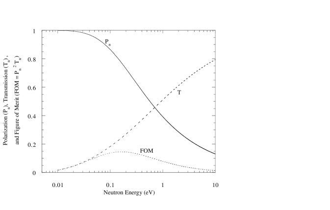
Figure 1 demonstrates the useful energy range of a spin filter with a fixed 3He thickness. To date the reported 3He polarizations with the rubidium spin-exchange method in large-volume cells are in the range of 40%–70% [25, 31, 33]. It is then possible to build practical 3He neutron spin filters for neutron energies up to tens of eV, limited ultimately by the velocity dependence of the neutron absorption cross section. The energy range of supermirror polarizers [39, 40] extends from cold to thermal neutron energies, but at epithermal energies the 3He spin filter competes only with the cryogenic polarized proton spin filter [41], which operates by spin-dependent scattering as opposed to spin-dependent absorption.
3 Accurate Neutron Beam Polarization Measurement
In this section we describe in detail the aspects of the neutron beamline and experimental apparatus which are important for understanding the measurements described in section 4.
3.1 LANSCE Pulsed Spallation Neutron Source
At the Manuel Lujan Neutron Scattering Center (MLNSC) at LANSCE, neutrons are produced by spallation. First, 500 s-wide, 800-MeV proton pulses are injected into the Los Alamos Proton Storage Ring (PSR). Inside the PSR, the pulses are compressed into triangular pulses 250 ns wide at the base before delivery to the spallation target at a rate of 20 Hz, producing unpolarized neutrons in the MeV energy range. The spallation target consists of two tungsten cylinders of 20 cm diameter. The cylinders are located one above the other along the vertical proton beam axis. The upper cylinder has a length of 7 cm, while the lower one is 27 cm long. The gap between them is 14 cm and is surrounded by moderation and reflector material. The horizontal flight paths are located at the level of the gap to minimize contamination of the beam from gamma-rays and high-energy neutrons. The experiment described here was performed on a flight path with a gadolinium-poisoned water moderator and a cadmium/boron liner. A more detailed description of the spallation source and the associated beamline is given in [43, 44].
The neutron yield from the water moderator surface has an approximately Maxwell-Boltzmann distribution at the effective temperature of the moderator, with a high-energy tail that falls off approximately like . This is shown in figure 2, which displays the neutron flux on the surface of the moderator calculated for an average proton current of A. The peak of the neutron flux for the water moderator used in this experiment, neutrons/(eVssr), is at about 40 meV [44]. , the number of neutrons per second in the epithermal energy range with energies between and in the beam, is approximately given by
| (7) |
Here , is the fraction of the cm2 moderator surface the detector views through the collimation, and is the detector solid angle ( sr).

The accuracy of the time-of-flight measurement depends on the length of the flight path (which in this experiment was about 60 m) and the width of the proton pulse. Further time broadening of the neutron pulse is introduced by the neutron moderation processes and the fact that the normal of the moderator surface is at a degree angle with respect to the flight path, leading to a distribution of lengths of the flight path of the neutrons across the beam profile. When the neutrons interact with the moderator, the neutron time spread can be described by the sum of two convolutions between a Gaussian and a pair of exponential tails as discussed in Ref. [45]. These time broadenings have an energy dependence. All of these effects are taken into account by the code FITXS [46] used to fit the energy calibration data.
3.2 Experimental Setup
The goal of the experiment was to study polarized 3He as a neutron spin filter, determine the accuracy of the beam polarization measurement technique, and discover the important sources of systematic error. Figure 3 shows schematically the main components of our experimental set up in flight path 2 at MLNSC.

A thin 3He/4He ion chamber combination was used to normalize the beam flux, with a statistical accuracy of per neutron pulse [47]. After the beam monitor, the neutrons were collimated to a beam of 1.1 cm in diameter. Then the neutrons interacted with a cell of 3He, located 9 m from the source. The 3He apparatus was mounted on a movable table so that two 3He cells, one polarized and one unpolarized, could be alternated in and out of the beam.
In addition to neutrons the beam contains a TOF-dependent gamma ray background. Detector backgrounds were determined by a modification of the absorber techniques described in Ref. [49]. A 0.13 mm thick In foil and a 2.6 mm thick Ta foil were both present in the beam during the experiment. The resonance absorption in these nuclei was used to determine the gamma background on-line — at energies corresponding to compound nuclear resonances in these nuclei, the neutron absorption cross section is large enough that, for these thicknesses, essentially no neutrons pass through the absorbers.
Because of the Maxwellian energy distribution of neutrons from the moderator, a few very low-energy neutrons are present. If detected, these neutrons can overlap in time with the faster neutrons of the next pulse (“frame overlap”) and complicate the interpretation of the transmission data. In our measurements, these low energy neutrons are absorbed in the 3He targets, due to the very large cross section of neutrons on 3He at these low energies. The water moderator is also poisoned with Gd to absorb low energy neutrons. As a result we expect (and observed) no frame overlap in our measurements.
Collimation and shielding of the neutron beam is accomplished by a combination of brass, lead, and polyethylene loaded with either boron or lithium. Brass collimators located immediately up-stream and downstream of the 3He gas cell define a 1.1 cm diameter beam. A lead wall with a 10 cm square hole is located downstream of the second set of brass collimators and limits the flux of fast neutrons entering the 40 m long evacuated beam pipe leading to the 3He scintillation detector. A series of borated polyethylene collimators with 10 cm diameter holes are located at regular intervals inside the beam pipe. A wall of lithium-loaded polyethylene with a 10 cm square hole is constructed 3 m from the detector. Attempts to locate shielding tightly around the detector were found to increase the background. Therefore the detector was left unshielded.
Neutrons were detected with a 3He gas scintillation detector. Discriminated PMT pulses were counted with a multiscaler. The neutron detector and associated electronics are described in section 3.4.
3.3 3He Spin Filter
3.3.1 Polarizing 3He with the Rb spin-exchange
3He gas was polarized using the Rb-spin exchange method. Intense circularly-polarized laser light ( nm) is used to optically pump the line of Rb atoms, polarizing them, in a glass sample cell. During binary collisions between the 3He and atomically polarized Rb in the cell, the hyperfine interaction induces polarization in the 3He. The resultant 3He polarization saturates at a value
| (8) |
where is the average Rb polarization produced by laser optical pumping and is the spin-exchange rate from the Rb to the 3He nucleus. is the 3He spin relaxation rate due to paramagnetic impurities on the cell wall and in the gas [51, 52, 53]. Due to the slow rate of the spin exchange polarization process, high 3He polarization requires 3He relaxation rates hours [51]. Rb densities of cm-3 are used.
Typical alkali-spin exchange apparatus can be found in Refs [25, 31, 33]. The most common lasers in use for the Rb optical pumping in high density 3He targets are Ti:sapphire lasers and high-power laser diode arrays (LDA) [25].
Two fiber-coupled LDAs [54] were used in this experiment. The unpolarized laser beam from the fiber was first focused and then linearly polarized with a beam polarizing cube. The linearly polarized component, which traversed the cube, was first circularly polarized with a quarter wave plate and then refocused so that the sample cell was completely covered by the light spot. The linearly polarized component which reflected from the cube was redirected parallel to the first beam with a mirror, and then circularly polarized by a second polarizing-cube/quarter-wave-plate pair. Thus the cylindrical 10-cm long cell was covered with four circularly polarized round light spots. The wavelength of the lasers were monitored by a spectrometer [55].
3.3.2 3He cells
The state of the art of the glass cell preparation for high 3He polarization is discussed in Ref. [24]. The cell construction is designed to optimize the FOM of the spin filter and meet practical considerations as well. The cells of this experiment were 10 cm long and 3.5 cm in diameter. The cylindrical part of the cell was produced from reblown Corning 1720 aluminosilicate glass with a wall thickness of about 3 mm. The ends of the cell, the neutron beam windows were made from 3 mm thick flat disks using 10B-free and low-iron content Corning 1720 glass. 10B has a large neutron capture cross section at thermal energies and would produce significant beam attenuation if present in the windows. Six cells were prepared for the experiment. The cells were loaded with 67 mbar of N2 and 3 – 11 bar 3He corresponding to 3He densities of cm-2. A destructive pressure test with water was performed with a few cells which had the same design. The maximum pressure before the burst was measured to be about 16 bar. The 3He polarization time constants varied from 40 h to 60 h. The cell used for this measurement had 3.3 bar 3He, for a 3He density of cm-2, and a measured relaxation time of approximately 45 hours. The highest polarization 3He with this cell was measured using the neutron beam to be 45%. Due to technical difficulties, this polarization could not be maintained, and the average polarization achieved for the measurement was near 20%. The 3He polarization direction was perpendicular to the neutron beam. The 86-cm diameter coils in the Helmholtz configuration were used to provide the holding field of 3.0 mT. The 3He polarization was monitored by the adiabatic fast passage method [56, 35].
The oven required to control the Rb density in the sample cell contained two almost identical 3He cells. One of the cells was continuously polarized by two lasers: the second cell, which contained approximately the same amount of 3He as the first, did not have any Rb so the 3He nuclei were not polarized. This cell was used as a reference cell. The cells were kept at temperature of about 175 oC for the optimum Rb density. The whole 3He apparatus was mounted on a movable table which allowed the cells to be alternated into and out of the beam every two minutes by switching the position of the table whose position was controlled with an accuracy of 0.2 mm. In one table position 2400 neutron pulses were accumulated, after which the table was moved to the other position. Each two-position cycle comprises one run. The data acquisition system separated information between the polarized cell and reference cell.
3.4 3He Scintillation Counter
A 3He scintillation detector was chosen as the transmission detector for its high efficiency in this neutron energy range, fast time response ( nsec), and insensitivity to gamma rays. The 3He scintillation detector utilizes the same large capture cross section for neutrons on 3He that is used in the polarizer: . Because the capture cross section depends on the neutron energy, the 3He thickness in the detector can be selected so that it has the optimum stopping power for the neutrons of interest. Thus the neutron detection efficiency of the cell with a given pressure depends on the neutron energy. However, since the neutron kinetic energy is small compared to the value of the reaction, the pulse height of the neutron capture event by 3He is constant.
The products from the reaction, triton and proton, have kinetic energy of 575 keV and 192 keV, respectively. The triton has a mean free path of 0.9 bar-cm in 3He gas and the proton mean-free path is 5.83 bar-cm. In the experiment we used a single cylindrical 3He scintillation detector cell with a diameter of 5 cm and length of 5 cm. We used typically 8 bar of 3He in the detector cell. The great majority of capture events deposit all their energy in the detector. The detector efficiency is then given by the neutron absorption in the cell:
| (9) |
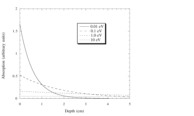
A small correction must be made to the detector efficiency when neutrons are captured near the wall of the detector, and subsequently do not deposit all their energy within the detector. This effect is energy dependent, since low energy neutrons have a higher absorption cross section and are therefore captured nearer the front of the detector (see figure 4). Since we require only a transmission , and the efficiency and “wall effect” are spin-independent, for the neutron polarization measurements no corrections need be made to the raw data to account for these effects. However, the energy dependence of the efficiency has a small effect on the calibration of the neutron TOF data in terms of neutron energy (discussed in section 4.2).
The detector cell was made from aluminum with a 5 mm thick entrance window for neutrons at the end of the cylinder. Scintillation light was detected through a 3 mm thick sapphire window which was mounted on the other end of the cylinder and was sealed with a Viton O-ring. The photomultiplier tube was a 2 inch diameter Amperex XP2262B which provided a fast rise time ( nsec) and a good quantum efficiency (% at nm).
The two charged particles, proton and triton, from the capture reaction produce vacuum ultraviolet (VUV) scintillation light in 3He gas through de-excitations of short-lived 3He quasi-molecules [57]. The n-3He reaction is estimated to produce 1-2 VUV photons per keV in 3He gas. It was impractical in our case to efficiently detect VUV photons. Therefore, the inside walls of the cell were coated with a wavelength shifter (WLS) to convert the VUV light to the visible region. The WLS was tetraphenylbutadiene (TPB, 1,1,4,4-Tetraphenyl-1,3-butadiene; Fluka ). The fluorescence efficiency of TPB has been studied recently by McKinsey et al. [58]. After the coatings were made, the cell was held at a temperature of C and pumped to a pressure below mbar for a day.
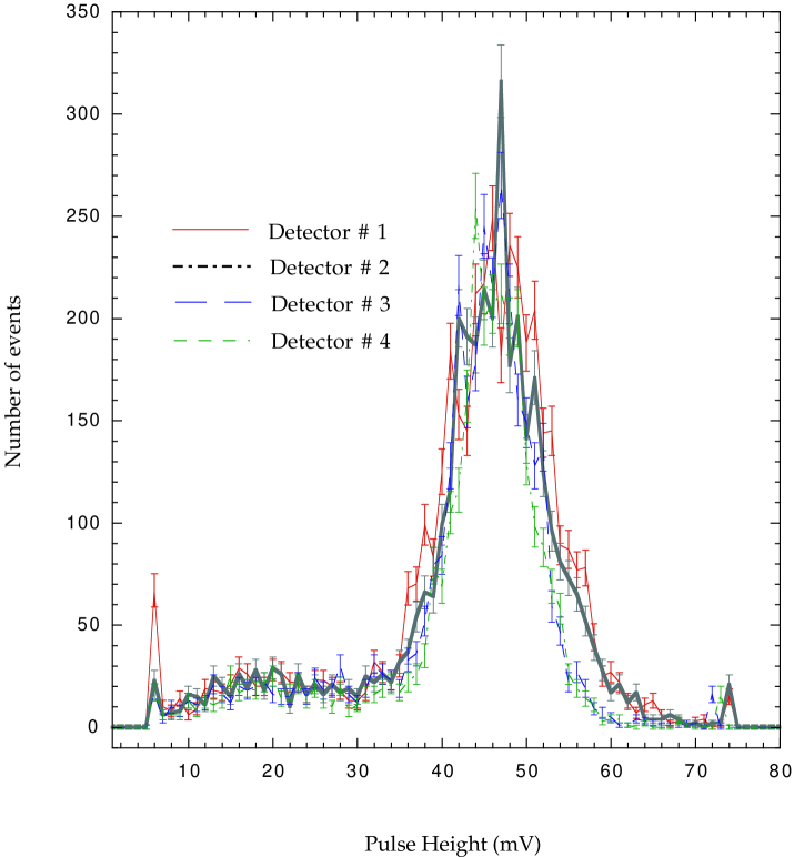
To increase the light output and improve the pulse height resolution, 7% of Xe gas by volume was added [59]. Figure 5 shows the pulse height distribution with the 3He-Xe mixture measured with thermal neutrons.
Pulses from the photomultiplier tube were fanned into three separate integral level discriminators whose outputs are in turn recorded in scalers. The first of the discriminator-scaler pairs is used to determine the neutron yield from which the transmission ratio is extracted, and is described in more detail in Sec. 3.5. The remaining two discriminator-scaler pairs are used to stabilize the gain of the photomultiplier tube. These discriminators are set at 60 mV and 120 mV, respectively. The lower discriminator is set in the minimum of the pulse height distribution from the detector and counts essentially all of the neutron events. The upper discriminator is centered at the peak of the pulse height distribution and has a count rate about half that of the lower level discriminator. At approximately five minute intervals, the data acquisition system reads both scaler values and adjusts the voltage of the photomultiplier tube until the scaler value associated with the 60 mV discriminator is approximately twice that of the 120 mV one. By this method the gain of the PMT was stabilized to the 1% level. Given the spectrum of pulse height shapes and the location of the discriminator windows, this stability suffices to reduce the fluctuation of the number of recorded neutron counts due to detector gain changes to a value which was below counting statistics.
3.5 Data Acquisition System
Pulses from the 3He scintillator are first passed through a 100 ns filter for shaping. They are then passed through a 10 amplifier before being pulse-height discriminated and recorded in an Ortec T914 [50] multiscaler that is divided into 9625 bins. Individual neutron counts are accumulated in a single multiscaler bin for a preset length of time, , until an external oscillator signals the multiscaler to advance to the next bin. The data are thus stored as histograms representing the number of scaler counts versus the neutron time of flight.
When the last TOF bin has been reached, the multiscaler returns to the first bin and waits for the next beam burst, which is preceded by a start signal from the proton storage ring. The same start signal triggers a countdown scaler set at 2400. New counts in each TOF bin are accumulated on top of those from the previous beam burst until the countdown scaler reaches zero. At this time data acquisition is halted, and the data stored in the multiscaler is written to disk. This process requires approximately one minute, during which the translation table for the target and empty cells is moved to the next position. The countdown scaler is reset to 2400, the multiscaler is cleared, and data acquisition recommences only after the multiscaler is finished writing to disk and the position transducer indicates that the translation table is in the correct position. Each target-in, target-out cycle comprises one run.
The multiscaler is read into CAMAC through a Kinetic Systems model 3344 serial line communication interface. The data-acquisition is based in VME, with online sorting handled on an HP-workstation by the XSYS data-acquisition package, as developed at IUCF [60].
4 Data Analysis and Results
In this section we describe the details of the measurement strategy, the data analysis, and the results.
4.1 Accurate neutron beam polarization measurement with transmission
The following method, which is a slight modification of the technique outlined earlier (defined by equation 1), was used to measure the neutron polarization. Both a target cell and a reference cell were placed on a translating table. Transmission through the target cell (polarized and unpolarized) was normalized by the transmission through the unpolarized reference cell. The relative normalization was measured every six minutes, thus reducing the effects of time-dependent drifts in the properties of various parts of the system to negligible levels.
To determine the neutron beam polarization, we first obtained the ratio of the transmissions through the unpolarized target cell () and the reference cell ():
| (10) |
The factor is energy dependent, and dominated by the differences in the 3He and window thicknesses for the two cells. We then polarized the target cell, and obtained the ratio of the transmissions through the target cell while polarized, , and the reference cell (always unpolarized), . From equation 5 we obtain the ratio of these transmissions
| (11) |
The values of both and depend upon the neutron energy. As long as the properties of the reference cell are static (i.e., constant 3He density), and we can take the ratio of equations 11 and 10 to get the ratio needed in equation 1 for extracting the neutron polarization:
| (12) |
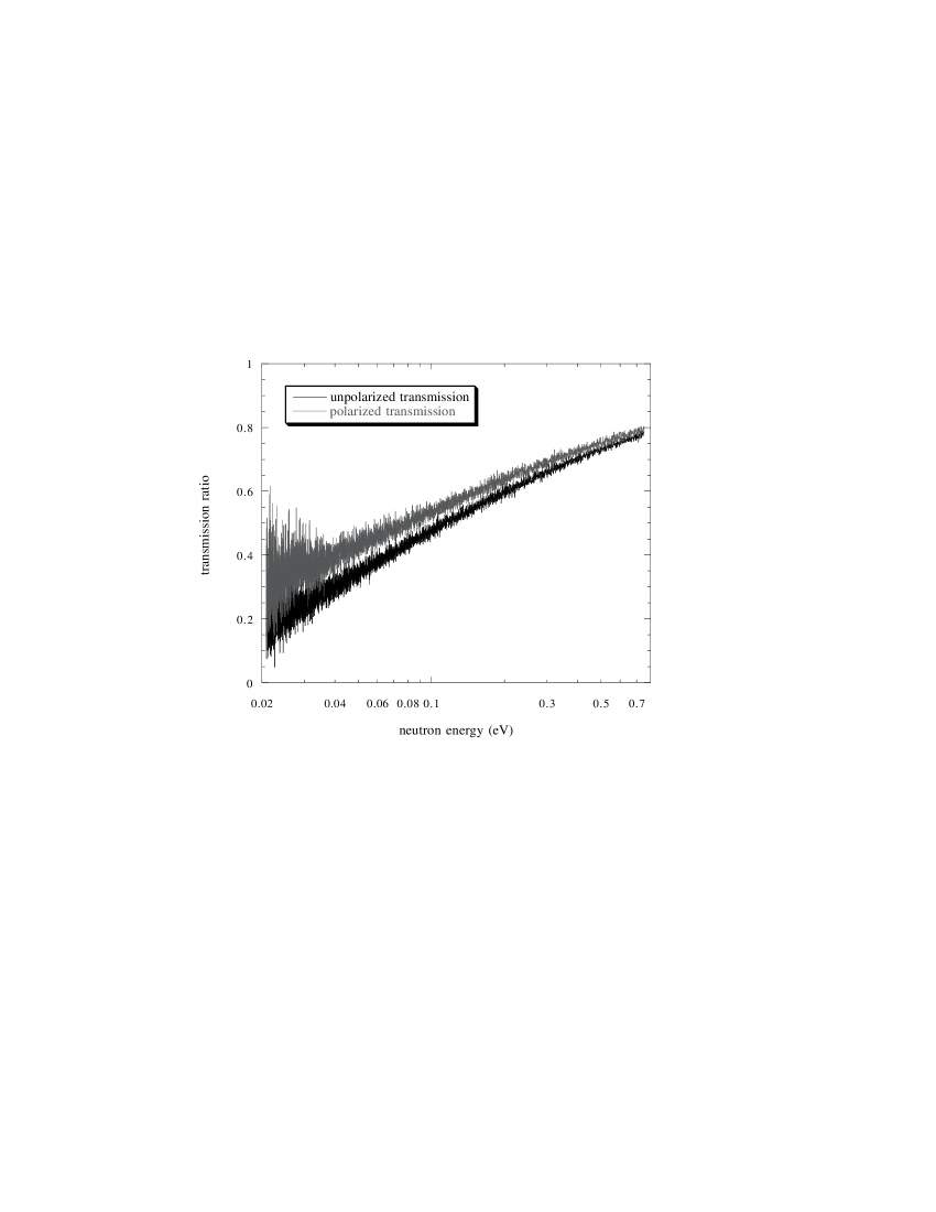
We thereby determine the argument, , that can be substituted into equation 4 to obtain beam polarization, . None of the individual parameters in the argument need be known. Figure 6 shows the transmission enhancement caused by 3He polarization as a function of neutron energy.
4.2 Neutron Time-of-Flight (TOF) and Energy Calibration
The neutron energy is determined by TOF, which for nonrelativistic neutrons is inversely proportional to the square-root of the neutron energy. For optimal resolution a long flight path and fine time binning are important. For this reason, and also to avoid a number of systematic effects associated with non-forward neutron scattering from the 3He target, the neutron detector is located approximately 60 m away from the neutron source and more than 50 m from the 3He target. Calibration of the TOF in terms of neutron energy is determined by installing thin films of 238U and natural Ir into the beam. These nuclei possess neutron resonances whose absolute energies are known to 0.1% or better (see table 1). Using the FITXS routine mentioned earlier, the centroid channel number of each of these resonances was extracted and correlated with the resonance energy. FITXS takes into account details of the beamline geometry and moderator properties including the emission time distribution of the neutrons from the moderator as a function of TOF.
| Nucleus | Resonance Energy (eV) |
|---|---|
| 191Ir | 0.6528 .0005 |
| 193Ir | 1.302 .001 |
| 238U | 6.671 .002 |
| 238U | 20.872 .006 |
| 238U | 36.680 .011 |
| 238U | 66.02 .02 |
| 238U | 189.67 .04 |
The neutron motion is nonrelativistic to an excellent approximation and the relation between the neutron kinetic energy and the TOF parameters is given by
| (13) |
where is the neutron mass, is the average path length from the source to the detector, is the channel number of the Ortec T914 multiscaler, is the size (in s) allocated for each TOF channel, and is a timing offset associated with the electronic start signal. Fitting the known energies of these resonances to the centroid of the channel number at which they appear in the neutron TOF spectra, we extract the TOF parameters and for neutrons of energies between 0.65 and 190 eV.
The offset is dependent on the dwell time of each TOF channel. For the 5.0 s channels used in this measurement, an offset of = 8.72(3) s was determined from the fit. This uncertainty, which contributes at levels below 0.1% starting at channel while our analysis begins at channel 300 (see figure 7), makes negligible contributions to the final uncertainty.
The average path length extracted was = 59.752(1) m, a value dominated by the high energy resonances used for TOF calibration. However, a correction to the path length must be made due to the energy dependent neutron penetration depth in the detector, which contributes strongly at energies lower than those used in the calibration. The probability that a neutron will be absorbed at a given depth in the detector is proportional to the neutron transmission to that depth, defined as = exp(). A series of absorption profiles are shown in figure 4. It may be shown (using equation 5, and the dependence of the neutron capture cross section as discussed in section 2) that the average penetration depth as a function of energy is given by
| (14) |
where is the number density of 3He atoms in the detector, and is the total thickness of the detector. This correction is largest at low energies (), where it approaches 2 cm, and nearly negligible at energies above those used in the fitting routines, (). The uncertainty in this correction is due to the uncertainty in the precise knowledge of the detector pressure (of order 5%), and to the variance in the penetration depth given by:
| (15) |
The net uncertainty in the path length is of order 0.04% at high energies (1 – 10 eV) and 0.01% at lower energies (0.01 – 0.1 eV). The net uncertainty in the energy scale is then 0.08% at high energies and 0.02% at lower energies (see figure 11).
4.3 Backgrounds
The largest source of backgrounds in this measurement are from fast neutrons scattered and moderated in the beam pipe and neutrons produced in secondary reactions at the source. These neutrons can reach the detector at a time different from their equal energy counterparts and thus blur the simple relation between neutron kinetic energy and TOF. The first source was greatly reduced by modifications to the collimation and shielding described previously. A lead wall was introduced to reduce the number of fast neutrons that enter the evacuated beam pipe. Within the beam pipe, the collimation is entirely 10B and 6Li doped polyethylene, which moderates and absorbs the extraneous neutrons rather than scattering them and forming secondary sources themselves. Other sources of backgrounds are small by comparison. Due to its low atomic number, the 3He scintillator is relatively insensitive to gammas present in the neutron beam. Cosmic rays background rates are low compared to the 20 kHz neutron counting rates.
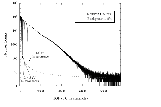
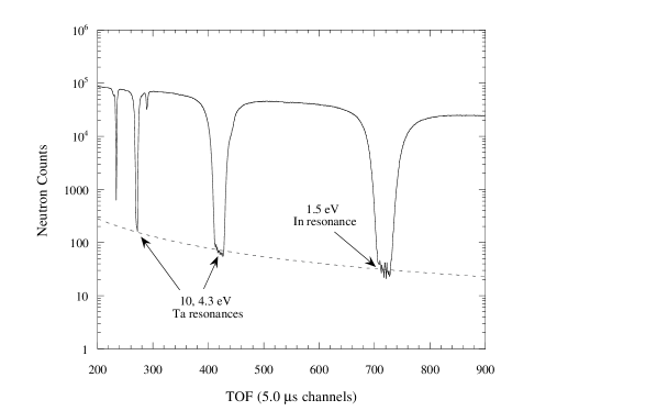
A typical TOF spectrum for this experiment is shown in Figure 7. Neutron resonances cause the dips in the transmission spectra. The resonances in this figure are from In and Ta foils inserted in the beam (Table 2), chosen because they possess large compound nuclear resonances at precisely known neutron energies. The thicknesses of the In and Ta samples were chosen to make them opaque to neutrons at these resonance energies. Consequently, any counts observed beneath one of these dips are either background counts or neutrons of slightly different energy which arrive at the resonance energy TOF due primarily to the spread of emission times from the moderator. The background rates were measured underneath these black resonances and at long TOF, where the low energy neutrons are absorbed by the 3He in the beam. The rates are then normalized to the neutron beam flux as measured by the beam monitor. Except for small TOF which is outside the region of our analysis, the background rates are well described by the expression:
| (16) |
where bkgnd is the measured background per channel, and is the channel number (see figure 7). The background is energy dependent, ranging from 0.2% at 10 eV down to 0.06% at 1.0 eV and back up to 1.5% at 40 meV. The extracted fits of the backgrounds to the above expression are accurate to better than 7%, with the subsequent uncertainty in the transmission maximal at the low and high energy extremes (0.1% at 40 meV, 0.015% at 10 eV) and nearly negligible in between (0.005% at 1.0 eV) (see figure 11).
| Nucleus | Resonance Energy (eV) |
|---|---|
| 115In | 1.5 |
| 181Ta | 4.3 |
| 181Ta | 10.4 |
| 181Ta | 40 |
| 181Ta | 36 |
| 59Co | 120 |
| 55Mn | 340 |
4.4 Deadtime and Pulse Pileup
If two or more events in the 3He scintillator with energies below the discriminator threshold overlap in time, the discriminator may register a count despite the fact that both events occur beneath the discriminator threshold. We call this pulse pileup: it increases the observed count rate relative to the true neutron rate at the detector. In addition, the detector-electronics combination is rendered insensitive for a brief time after an event is registered. We call this deadtime: it decreases the observed count rate relative to the true neutron rate.
Pulse pileup and deadtime effects are difficult to model reliably. We therefore decided to measure the net effects of deadtime and pulse pileup experimentally. The first aspect of our measurement strategy is to keep the deadtime and pileup corrections small. The 3He detectors have a response time of approximately 100ns. Instantaneous counting rates at the detector were intentionally reduced by the beam collimation to less than 50kHz (20 kHz with 3He in the beam). An order of magnitude estimate of the deadtime losses is then 0.2%.
The next aspect of our strategy is to ensure that the deadtime/pileup corrections are dominated by processes occuring in the detector and not later on in the electronics chain. The ORTEC multiscaler possessed a 7 nsec deadtime, and the pulse width from the discriminator was 20 nsec. Both of these values are smaller than the width of the pulses from the detector, and therefore none of the electronics at or after the discriminator contribute to the deadtime.
To first order, the observed yield at the detector is then given by:
| (17) |
where (Hz) is the observed rate, (Hz) is the true rate, and (sec) is a parameter which includes the effects of both deadtime and pileup. This relation is good for 1, which our system satisfies.
To determine this parameter , we performed a measurement of the total cross section on a nucleus whose neutron cross section is independent of energy. Measurements of the neutron total cross section may be performed with our apparatus by replacing the two 3He cells with the sample. The cross section is given in terms of measured parameters by:
| (18) |
where is the total neutron-target cross section, is the number density of atoms in the target, is the target thickness, and out and in are the true rates for the target out and target in the beam respectively. Using only the approximation that the deadtime correction is small, these equations may be combined to extract the deadtime parameter, :
| (19) |
where is the uncorrected cross-section with no deadtime corrections applied to the transmission data (background corrections are included), is the true cross section of the sample, and is the sample in versus sample out difference in rates (Hz).
Total cross section measurements on a single carbon sample at four different detector counting rates from approximately 20kHz to 120kHz were performed. Carbon was chosen because it has a total cross section which has been accurately measured and is independent of neutron energy to an excellent approximation in this energy range [61]. The rates were changed by varying the thicknesses of Pb attenuators and In and Ta filters in the beam. The extracted cross sections for the four measurements were then compared over nine different energy regimes. The measured cross sections were plotted versus the difference in rates to extract the deadtime parameter from the slope of the curve. This measurement of the deadtime parameter yields = 47(7) ns, which is a reasonable value given the 100 ns response of the detectors coupled with pileup effects.
The instantaneous rates at the detector was 20 kHz at higher neutron energies (), and near 200 – 500 Hz at lower neutron energies (0.4 – 0.5 eV). The correction to the detector yield is then 0.1% at the higher neutron energy, 0.01 – 0.025% at lower neutron energy. We exploit the fact that, since we perform a relative transmission measurement, we are sensitive ultimately only to the difference in deatime/pileup corrections for the polarized and unpolarized 3He — the correction to the transmission ratio is proportional to R. The difference in thicknesses of the reference and target cells was 25%, making the correction to the transmission ratio 0.020(4)% for , and 0.0025(4) for (see figure 11).
4.5 Results
We constructed a model based on the operation of the neutron polarizer as outlined in the introduction and on the behavior of the neutron cross section on 3He discussed in Section 2 and used it to fit our data. 211 runs were accumulated with the target cell unpolarized, 119 with the target polarized. Additional runs were accumulated while the target was being polarized. The rise of the 3He polarization is very nearly an exponential, with possible deviations due to fluctuations in Rb density (from temperature fluctuations), for example. By observing the change in transmission as the 3He polarization slowly increased, we extracted the rise time of the polarization, hours, and the asymptotic value of the transmission parameter . The 119 “polarization” runs were accumulated with the 3He initially within 0.8% of the asymptotic transmission, with later runs within 0.1%. For each run the transmission through each 3He cell was normalized to the beam monitor, and corrected for background and deadtime/pileup effects. The transmission through the polarized 3He cell was then scaled at each run by a factor:
| (20) |
from equation 5, where is the asymptotic value of the 3He polarization, and the polarization in the denominator is determined by the time constant noted above. The runs were then summed together to improve the statistics for analysis. The effect of the scaling was negligible at high energies (for , the average effect was ) and largest at low energies (for , ). See figure 11.
Following the experimental procedure outlined in section 4.1, we first consider the unpolarized target runs. The transmission ratio for both target and reference cells unpolarized is given (from equation 5) by:
| (21) |
where is the difference in the 3He thicknesses, and the coefficient allows for an energy independent difference in transmission (due to differences in potential scattering from the windows of the glass cells, for example). Since the cross section follows the well known dependence described earlier, this relation can be rewritten as a function of TOF:
| (22) |
where is the cross section at the neutron energy , is the neutron mass, is the flight path length, is the neutron time of flight, is the offset between the start of the beam burst and the start of counting at the data acquisition system. A fit to the transmission data for both cells unpolarized yields a measured difference in target and reference cell thicknesses of = 2.896(3) (consistent with a target cell thickness of 33 bar-cm and a reference cell thickness of 40 bar-cm). was measured to be -0.357(4). This means that the difference in neutron transmission through the two cells at very high neutron energies was about 30%.
The transmission ratio for runs with polarized target and unpolarized reference cell was then divided TOF-channel-by-channel by the unpolarized target ratio, yielding the normalized transmission ratio in equation 12. Rewriting as a function of energy:
| (23) |
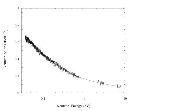
A fit of the transmission data to this functional form yields the product . Presuming a 30 bar-cm target, this corresponds to a 3He polarization of 20%. The uncertainty in this parameter yields an energy dependent statistical uncertainty that varies from 0.3% at 40 meV to 0.01% at 10 eV. Systematic effects, dominated by uncertainties in backgrounds, deadtime/pileup effects, energy calibration, and the time dependence of the target polarization (see the following section) contribute an additional energy dependent error, which peaks at high and low energies near 0.1%. At a neutron energy of 0.1 eV, the neutron polarization is 0.4616(15). The polarization as a function of energy given by this fit is shown with the data in figure 9.
5 Statistical Accuracy and Systematic Effects
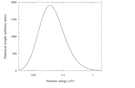
The measurement was limited in accuracy by counting statistics. Since the beam polarization measurement is a transmission measurement, the statistical precision of the measurement can be estimated by calculating the statistical weight over the neutron energy range of interest:
| (24) |
where
| (25) |
Here is the run time of the measurement, is the energy bin, is the number of neutrons per second with energies between and (corrected for the presence of background filters In and Ta and other attenuating material in the beam) (see equation 7), is the neutron transmission from equation 5, is the neutron polarization from equation 1, and is the detector efficiency. In figure 10 we have plotted the calculated weight as a function of neutron energy for a 3.3 bar-cm target cell with = 20%. The statistical precision of this measurement calculated in this way is estimated to be 0.16%. Achievement of the 0.1% absolute accuracy goal for this measurement, with the given neutron flux, would require either 2.5 times the total run time (from 33 hours to 82.5 hours) or an improvement in 3He polarization to 32% or better.
There are a number of small systematic effects which must be considered to assess the absolute accuracy of this technique. The transmission formula gives the polarization of the neutrons under the following assumptions: (1) the rate of removal of the polarized 3He atoms from the target by the beam is negligible, (2) the neutron beam is perfectly collimated and the neutron scattering in the target is negligible in comparison with the absorption cross section, so that all of the neutrons pass through the same length of target, (3) multiple scattering into the forward direction is negligible, (4) the neutrons are not depolarized as they pass out of the 3He by spin-flip scattering in the window, (5) the spin-dependent attenuation of the neutrons in 3He is the only neutron spin-dependent process in the target, (6) changes in the kinetic energy of the neutrons as they pass into and out of the holding magnetic field and the neutron optical potential for the polarized 3He gas are negligible, so that the neutron kinetic energy in the target is given correctly by measurements outside the target, (7) the 3He polarization in the target cell is uniform across the beam profile, (8) the spin dependent Mott-Schwinger scattering can be neglected, (9) the effect of the finite temperature of the 3He gas is negligible, (10) the incident neutron polarization is zero. Because of the large distance between the target and detector in this measurement (the detector intercepts a solid angle of sr), almost all of these effects are completely negligible. Such effects in the gas are further suppressed by the absorption cross section in 3He, which is large compared to the scattering and absorption cross sections of window materials and the scattering cross section of 3He itself.
| Correction (%) | Uncertainty (%) | Source of correction |
|---|---|---|
| 0.0 – 0.26 | 0.0 – 0.05 | time dependence of target 3He polarization |
| 0.0 | 0.02 – 0.08 | energy scale determination |
| -(1.5 – 0.06) | 0.1 – 0.0 | detector backgrounds |
| -(0.0 – 0.025) | 0.0 – 0.004 | detector dead time and pulse pileup |
| 0.0 | 0.0 | distribution of neutron path lengths in target |
| 0.0 | 0.0 | multiple scattering in target |
| 0.0 | 0.0 | depolarization of neutrons in glass of the cell |
| 0.0 | 0.0 | small angle scattering in glass of cell |
| 0.0 | 0.0 | corrections from Mott-Schwinger scattering |
| 0.0 | 0.0 | corrections from thermal motion of the 3He atoms |
| -1.5 – 0.17 | 0.10 – 0.10 | Net correction for systematic effects |
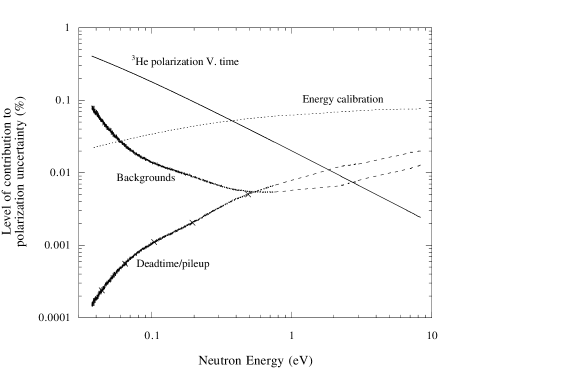
In Table 3 we show a list of systematic effects from various sources for the target conditions in our experiment. We have included all known effects which modify the transmission expression by at least 0.01% in the energy range of our measurement. The largest systematic effect is due to the slowly rising 3He polarization, an effect which may be made negligible if more time is available for ramping up the 3He polarization. Otherwise, deadtime/pileup corrections, detector backgrounds and energy calibration give the largest effects, which are at the 0.02% level. These effects are plotted as a function of neutron energy in figure 11. For this reason we are confident that it is possible to improve the absolute accuracy of this technique to the 0.02% level.
One question that arises is whether or not all of the techniques described in this measurement can be extrapolated to the lower neutron energies of interest in fundamental physics experiments. For example, it becomes impractical to calibrate the neutron TOF spectrum by transmission through neutron resonances with absolutely known resonance energies, since such resonances broaden and disappear as one approaches neutron threshold. One alternative to this procedure which is well-suited to a transmission measurement is to use the sharp change in transmission through polycrystalline solids at neutron energies corresponding to Bragg scattering conditions. The discontinuity in the total cross section for neutron energies above and below the Bragg condition is clearly visible in a neutron TOF transmission spectrum and occurs at a well-defined neutron energy. In addition, the pulse height resolution of the 3He scintillator detector will worsen as the low energy neutrons are absorbed close to the detector wall and the reaction products do not deposit the full energy of the reaction into the gas. The neutron detector efficiency then develops an energy dependence which is influenced directly by the detector geometry. This problem can be avoided by using a detector not based on absorption in helium gas. The sensitivity of the detector to gamma backgrounds must then be assessed. Finally, in many cases it may not be practical to locate the transmission detector so far from the polarized target. In this case all of the systematic effects not important for our geometry must be evaluated in detail to judge the limit to absolute accuracy.
6 Summary
Using a laser-polarized 3He spin filter we have measured the absolute neutron beam polarization from 40 meV to 10 eV with an absolute accuracy of 0.3%, where 0.2% is from counting statistics, and 0.1% is the systematic error. The measurement was performed with 3He polarized to about 20% with the Rb-spin exchange method. We have demonstrated that the simplicity of the mechanism of neutron polarization in polarized 3He gas allows for a new and reliable way of measuring and monitoring on-line the absolute polarization of a low energy neutron beam to better than 0.1%. The use of 3He spin filters to measure and monitor the beam polarization does not require a spin flipper or analyzer. It depends only upon the well defined relationship for neutron transmission through polarized 3He gas. The 3He filter provides a possibility for continuous online measurement and control of the neutron polarization. The extension of the technique to lower neutron energies is straightforward.
In addition to the fundamental neutron physics applications, the development of neutron polarizers and analyzers based on 3He spin filters is important for neutron scattering. Neutron scattering studies in the thermal and epithermal energy range have suffered for years from a lack of a convenient source of polarized neutrons. With a 3He spin filter the useful range can be expanded to epithermal neutron wavelengths.
One of the advantages of the 3He spin filter is its simplified experimental configuration. One does not require any major modifications to the beamline for a beam polarization measurement to be made. Compact configurations are possible because there will be no gamma production and the 3He filter has a large acceptance angle, allowing the filter and experiment to be mounted close to the source. The accurate absolute measurement described in this work demonstrates that the simple relations between the polarized target parameters and the neutron transmission and polarization are satisfied to high accuracy in practical polarized 3He devices.
7 Acknowledgements
The authors would like to thank Mr. M. Souza for his enthusiasm, advice, and great glass blowing skills, and Mr. T. Langston and Mr. J. Sandoval for their technical help during the experiment. This work has benefited from the use of the Los Alamos Neutron Science Center at the Los Alamos National Laboratory. This facility is funded by the US Department of Energy and operated by the University of California under Contract W-7405-ENG-36. The work was also supported by NSF CAREER Award NSF-PHY-9501312 and DOE award DE-FG02-96ER45587.
References
- [1] D. Dubbers, Prog. in Part. and Nucl. Phys. A26, 173 (1991).
- [2] S. J. Freedman, J. Phys. (Paris), Colloque C6, 239 (1990).
- [3] H. Abele, S. Bäler, D. Dubbers, et al., Phys. Lett. 407 B, 212 (1997).
- [4] G. Savard, A. Galindo-Uribarri, E. Hagberg, J. C. Hardy, V. T. Koslowsky, D. C. Radford, and I. S. Towner, Phys. Rev. Lett 74, 1521 (1995).
- [5] A. S. Carnoy et al., Phys. Rev. Lett. 65, 3249 (1990).
- [6] I. S. Towner and J. C. Hardy, nucl-th19812036.
- [7] A. P. Serebrov, I. A. Kuznetsov, I. V. Stepanenko, et al., JETP 113, 1963 (1998).
- [8] R. Golub, D. Richardson, and S. Lamoreaux, Ultra-Cold Neutrons, Adam Hilger, 1991.
- [9] J. Sherwood, I. Stephenson, S. Bernstein, Phys. Rev. 96, 1546 (1954).
- [10] H. Hassler, G. Weber, Atomenergie 7, 170 (1962).
- [11] B. Erozolimskii, Y. Mostovoi, B. Obinyakov, Prib. Tech. Exp. N2, 39 (1964).
- [12] Barkan, Bieber, and M. Burgy, Rev. Sci. Inst. 39, 101 (1968).
- [13] B. Hamelin, N. Xiromeritis, P. Liaud, Nucl. Inst. Meth. 125, 79 (1975).
- [14] O. Halpern, Phys. Rev. 59, 981(1941).
- [15] D. Hughes, J. Wallace, and R. Holzman, Phys. Rev. 73, 1277(1948).
- [16] D. Hughes, M. Burgy, Phys. Rev. 81, 498 (1951).
- [17] C. Shull, E. Wollan, Phys. Rev. 81, 695 (1951).
- [18] H. Kendrick, S. Werner, A. Arrot, Nucl. Instrum. Methods 68, 50 (1969).
- [19] W. Vorberg, Nucl. Instrum. Methods 145, 311 (1977).
- [20] H. Nastoll et al., Nucl. Instrum. Methods A 306, 6572 (1991).
- [21] A. Serebrov et al.,Nucl. Inst. Meth. A 357, 503 (1995).
- [22] B. G. Yerozolimsky, Nucl. Instrum Methods A 420, 232 (1999).
- [23] G. L. Greene, A. K. Thompson and M. S. Dewey, Nucl. Instrum. Methods A 356, 177 (1995).
- [24] T. E. Chupp et al., J. Neutron Physics 5, 11 (1995).
- [25] W. J. Cummings, O. Häusser, W. Lorenzon, D. R. Swenson and B. Larson, Phys. Rev. A 51, 4842 (1995).
- [26] T. G. Walker and W. Happer, Rev. Mod. Phys. 69, 629 (1997).
- [27] F. Tasset, T. E. Chupp, J. P. Pique, A. Steinhof, A. Thompson, E. Wasserman, and M. Ziade, Physica B 180 & 181, 896 (1992).
- [28] R. Surkau et al., Nucl. Instrum. Methods A 384, 444 (1997).
- [29] G. L. Jones, T. R. Gentile, A. K. Thompson, Z. Chowdhuri, M. S. Dewey, W. M. Snow, and F. E. Wietfeldt, submitted to NIM, (1999).
- [30] O. Zimmer, et al., submitted to Phys. Rev. Letters, (1998).
- [31] B. Larson, O. Häusser, P. P. J. Delheij, D. M. Whittal, and D. Thiessen,Phys. Rev. C 44, 3108 (1991).
- [32] T. E. Chupp, R. A. Loveman, A. K. Thompson, A. M. Bernstein and D. R. Tieger, Phys. Rev. C 45, 915 (1992).
- [33] J. R. Johnson, et al., Nucl. Instrum. Methods A 356, 148 (1995).
- [34] M. A. Espy et al., Phys. Rev. C 56, 2607 (1997).
- [35] K. P. Coulter et al., Nucl. Instrum Methods A 288, 463 (1990).
- [36] F. L. H. Wolfs, S. J. Freedman, J. E. Nelson, M. S. Dewey, and G. L. Greene, Phys. Rev. Lett. 63, 2721 (1989).
- [37] J. Als-Nielsen and O. Dietrich, Phys. Rev. 133, B925 (1964).
- [38] L. Passell and R. L. Schermer, Phys. Rev. 150, 146 (1966).
- [39] O. Schaerpf, Physica B 156 & 157, 631 (1989).
- [40] F. Mezei, Comm. on Physics 1, 81 (1976).
- [41] S. I. Penttilä, et al., Proc. of the 11th International Symposium on High Energy Spin Physics, ed. K J. Heller and S. L. Smith (AIP Conference Proceedings No 343,1995) p. 532.
- [42] F. Tasset and E. Ressouche, Nucl. Instrum. Methods A 356, 177 (1995).
- [43] N. R. Roberson et al., Nucl. Instrum. Methods A 326, 549 (1993).
- [44] P. W. Lisowski, C. D. Bowman, G. J. Russell and S. A. Wender, Nucl. Sci. Eng. 106, 208 (1990).
- [45] B. E. Crawford, Ph.D. dissertation, Duke University, 1997; B. E. Crawford et al., Phys. Rev. C 58, 1225 (1998).
- [46] J. D. Bowman, Y. Matsuda, Y. F. Yen, and B. E. Crawford, computer code for analysis of neutron time-of-flight spectra, 1997 (unpublished).
- [47] J. D. Bowman, J. J. Szymanski, V. W. Yuan, C. D. Bowman, A. Silverman and X. Zhu, Nucl. Instrum. Methods A 297, 183 (1990).
- [48] C. Keith et al., forthcoming publication.
- [49] Yi-Fen Yen, J. D. Bowman, L. Y. Lowie, G. E. Mitchell, Y. Masuda, and S. Penttilä, Nucl. Instrum. Methods A 397, 365 (1997).
- [50] Model number is Turbo-MCS T914, EG&G ORTEC. No approval or endorsement of any commercial product by the National Institute of Standards and Technology is intended or implied. Certain commercial equipment, instruments, or materials are identified in this report in order to facilitate understanding. Such identification does not imply recommendation or endorsement by the National Institute of Standards and Technology, nor does it imply that the materials or equipment identified are necessarily the best available for the purpose.
- [51] W. Fitzsimmons, L. Tankersly and G. Walters, Phys. Rev. 179, 156 (1969).
- [52] R. S. Timsit, J. M. Daniels and A. D. May, Can. J. Physics 49, 560 (1971).
- [53] N. R. Newbury, A. S. Barton, G. D. Cates, W. Happer and H. Middleton, Phys. Rev. A 48, 4411 (1993).
- [54] Model number is OPC-A015-795-FCPS, Opto Power Corp., Tucsan, AZ.
- [55] Model number is S2000, Ocean Optics, Inc., Dunedin, FL.
- [56] K. P. Coulter et al., Nucl. Instrum. Methods A 270, 90 (1988).
- [57] P. Grimm, F.-J. Hambsch, M. Mutterer, J. P. Theobald and S. Kubota, Nucl. Instrum. and Methods A 262, 394 (1987).
- [58] D. N. McKinsey et al., Nucl. Instrum. Methods B 132, 351 (1997).
- [59] J. A. Northrop and Judith C. Gursky, Nucl. Instrum. Methods 3, 207 (1958).
- [60] N. R. Yoder, Presented at Real-Time Conference, (1993).
- [61] J. Schmiedmayer, H. Rauch, and P. Riehs, Phys. Rev. Lett. 61, 1065 (1988).