OPTICAL DIPOLE TRAPS FOR NEUTRAL ATOMS
Contents
toc
I Introduction
Methods for storage and trapping of charged and neutral particles have very often served as the experimental key to great scientific advances, covering physics in the vast energy range from elementary particles to ultracold atomic quantum matter. The ultralow-energy region became experimentally accessible as a result of the dramatic developments in the field of laser cooling and trapping, which have taken place over the last two decades (Stenholm, 1986; Minogin and Letokhov, 1988; Arimondo et al., 1992; Metcalf and van der Straten, 1994; Chu, 1998; Cohen-Tannoudji, 1998; Phillips, 1998).
For charged particles, the strong Coulomb interaction can be used for trapping in electric or electromagnetic fields (Bergström et al., 1995; Ghosh, 1995). At the very low temperatures reached by laser cooling, single ions show a variety of interesting quantum effects (Wineland et al., 1995), and ensembles form a crystalline ordered state (Walther, 1993). Laser cooling in ion traps has opened up completely new possibilities for ultrahigh precision spectroscopy and related fundamental applications (Thompson, 1993). It is a very important feature of ion traps that the confining mechanism does not rely on the internal structure of the ion, which is therefore accessible for all kinds of experiments.
For neutral atoms, it has become experimental routine to produce ensembles in the mikrokelvin region, and many experiments are being performed with such laser-cooled ultracold gases. It is thus possible to trap the atoms by much weaker mechanisms as compared to the Coulomb interaction. Traps for neutral atoms can be realized on the basis of three different interactions, each class having specific properties and offering particular advantages:
-
Radiation-pressure traps operating with near-resonant light (Pritchard et al., 1986; Raab et al., 1987) have a typical depth of a few Kelvin, and because of very strong dissipation they allow to capture and accumulate atoms even from a thermal gas. In these traps, the atomic ensemble can be cooled down to temperatures in the range of a few 10 K. The trap performance, however, is limited in several ways by the strong optical excitation: The attainable temperature is limited by the photon recoil, the achievable density is limited by radiation trapping and light-assisted inelastic collisions, and the internal dynamics is strongly perturbed by resonant processes on a time scale in the order of a microsecond.
-
Magnetic traps (Migdall et al., 1986; Bergeman et al., 1987) are based on the state-dependent force on the magnetic dipole moment in an inhomogeneous field. They represent ideal conservative traps with typical depths in the order of 100 mK, and are excellent tools for evaporative cooling and Bose-Einstein condensation. For further applications, a fundamental restriction is imposed by the fact that the trapping mechanism relies on the internal atomic state. This means that experiments concerning the internal dynamics are limited to a few special cases. Furthermore, possible trapping geometries are restricted by the necessity to use arrangements of coils or permanent magnets.
-
Optical dipole traps rely on the electric dipole interaction with far-detuned light, which is much weaker than all mechanisms discussed above. Typical trap depths are in the range below one millikelvin. The optical excitation can be kept extremely low, so that such a trap is not limited by the light-induced mechanisms present in radiation-pressure traps. Under appropriate conditions, the trapping mechanism is independent of the particular sub-level of the electronic ground state. The internal ground-state dynamics can thus be fully exploited for experiments, which is possible on a time scale of many seconds. Moreover, a great variety of different trapping geometries can be realized as, e.g., highly anisotropic or multi-well potentials.
The subject of this review are atom traps of the last described class along with their unique features as storage devices at ultralow energies.
Historically, the optical dipole force, acting as confining mechanism in a dipole trap, was first considered by Askar’yan (1962) in connection with plasmas as well as neutral atoms. The possibility of trapping atoms with this force was considered by Letokhov (1968) who suggested that atoms might be one-dimensionally confined at the nodes or antinodes of a standing wave tuned far below or above the atomic transition frequency. Ashkin (1970) demonstrated the trapping of micron-sized particles in laser light based on the combined action of radiation pressure and the dipole force. Later he suggested three-dimensional traps for neutral atoms (1978). The dipole force on neutral atoms was demontrated by Bjorkholm et al. (1978) by focusing an atomic beam by means of a focused laser beam. As a great breakthrough, Chu et al. (1986) exploited this force to realize the first optical trap for neutral atoms. After this demonstration, enormous progress in laser cooling and trapping was made in many different directions, and much colder and denser atomic samples became available for the efficient loading of shallow dipole traps. In the early ’90s optical dipole forces began to attract rapidly increasing interest not only for atom trapping, but also in the emerging field of atom optics (Adams et al., 1994).
In this review, we focus on dipole traps realized with far-detuned light. In these traps an ultracold ensemble of atoms is confined in a nearly conservative potential well with very weak influence from spontaneous photon scattering. The basic physics of the dipole interaction is discussed in Sec. II. The experimental background of dipole trapping experiments is then explained in Sec. III. Specific trapping schemes and experiments are presented in Secs. IV and V, where we explore the wide range of applications of dipole traps considering particular examples.
II Optical dipole potential
Here we introduce the basic concepts of atom trapping in optical dipole potentials that result from the interaction with far-detuned light. In this case of particular interest, the optical excitation is very low and the radiation force due to photon scattering is negligible as compared to the dipole force. In Sec. II A, we first consider the atom as a simple classical or quantum-mechanical oscillator to derive the main equations for the optical dipole interaction. We then discuss the case of real multi-level atoms in Sec. II B, in particular of alkali atoms as used in the great majority of experiments. discussed
A Oscillator model
The optical dipole force arises from the dispersive interaction of the induced atomic dipole moment with the intensity gradient of the light field (Askar’yan, 1962; Kazantsev, 1973; Cook, 1979; Gordon and Ashkin, 1980). Because of its conservative character, the force can be derived from a potential, the minima of which can be used for atom trapping. The absorptive part of the dipole interaction in far-detuned light leads to residual photon scattering of the trapping light, which sets limits to the performance of dipole traps. In the following, we derive the basic equations for the dipole potential and the scattering rate by considering the atom as a simple oscillator subject to the classical radiation field.
1 Interaction of induced dipole with driving field
When an atom is placed into laser light, the electric field induces an atomic dipole moment that oscillates at the driving frequency . In the usual complex notation and , where is the unit polarization vector, the amplitude of the dipole moment is simply related to the field amplitude by
| (1) |
Here is the complex polarizability, which depends on the driving frequency .
The interaction potential of the induced dipole moment in the driving field is given by
| (2) |
where the angular brackets denote the time average over the rapid oscillating terms, the field intensity is , and the factor takes into account that the dipole moment is an induced, not a permanent one. The potential energy of the atom in the field is thus proportional to the intensity and to the real part of the polarizability, which describes the in-phase component of the dipole oscillation being responsible for the dispersive properties of the interaction. The dipole force results from the gradient of the interaction potential
| (3) |
It is thus a conservative force, proportional to the intensity gradient of the driving field.
The power absorbed by the oscillator from the driving field (and re-emitted as dipole radiation) is given by
| (4) |
The absorption results from the imaginary part of the polarizability, which describes the out-of-phase component of the dipole oscillation. Considering the light as a stream of photons , the absorption can be interpreted in terms of photon scattering in cycles of absorption and subsequent spontaneous reemisson processes. The corresponding scattering rate is
| (5) |
We have now expressed the two main quantities of interest for dipole traps, the interaction potential and the scattered radiation power, in terms of the position-dependent field intensity and the polarizability . We point out that these expressions are valid for any polarizable neutral particle in an oscillating electric field. This can be an atom in a near-resonant or far off-resonant laser field, or even a molecule in an optical or microwave field.
2 Atomic polarizability
In order to calculate its polarizability , we first consider the atom in Lorentz’s model of a classical oscillator. In this simple and very useful picture, an electron (mass , elementary charge ) is considered to be bound elastically to the core with an oscillation eigenfrequency corresponding to the optical transition frequency. Damping results from the dipole radiation of the oscillating electron according to Larmor’s well-known formula (see, e.g., Jackson, 1962) for the power radiated by an accelerated charge.
It is straightforward to calculate the polarizability by integration of the equation of motion for the driven oscillation of the electron with the result
| (6) |
Here
| (7) |
is the classical damping rate due to the radiative energy loss. Substituting and introducing the on-resonance damping rate , we put Eq. 6 into the form
| (8) |
In a semiclassical approach, described in many textbooks, the atomic polarizability can be calculated by considering the atom as a two-level quantum system interacting with the classical radiation field. One finds that, when saturation effects can be neglected, the semi-classical calculation yields exactly the same result as the classical calculation with only one modification: In general, the damping rate (corresponding to the spontaneous decay rate of the excited level) can no longer be calculated from Larmor’s formula, but it is determined by the dipole matrix element between ground and excited state,
| (9) |
For many atoms with a strong dipole-allowed transition starting from its ground state, the classical formula Eq. 7 nevertheless provides a good approximation to the spontaneous decay rate. For the lines of the alkali atoms Na, K, Rb, and Cs, the classical result agrees with the true decay rate to within a few percent.
An important difference between the quantum-mechanical and the classical oscillator is the possible occurence of saturation. At too high intensities of the driving field, the excited state gets strongly populated and the above result (Eq. 8) is no longer valid. For dipole trapping, however, we are essentially interested in the far-detuned case with very low saturation and thus very low scattering rates (). We can thus use expression Eq. 8 also as an excellent approximation for the quantum-mechanical oscillator.
3 Dipole potential and scattering rate
With the above expression for the polarizability of the atomic oscillator the following explicit expressions are derived for the dipole potential and the scattering rate in the relevant case of large detunings and negligible saturation:
| (10) |
| (11) |
These general expressions are valid for any driving frequency and show two resonant contributions: Besides the usually considered resonance at , there is also the so-called counter-rotating term resonant at .
In most experiments, the laser is tuned relatively close to the resonance at such that the detuning fulfills . In this case, the counter-rotating term can be neglected in the well-known rotating-wave approximation (see, e.g., Allen and Eberly, 1972), and one can set . This approximation will be made throughout this article with a few exceptions discussed in Chapter IV.
In this case of main practical interest, the general expressions for the dipole potential and the scattering rate simplify to
| (12) |
| (13) |
The basic physics of dipole trapping in far-detuned laser fields can be understood on the basis of these two equations. Obviously, a simple relation exists between the scattering rate and the dipole potential,
| (14) |
which is a direct consequence of the fundamental relation between the absorptive and dispersive response of the oscillator. Moreover, these equations show two very essential points for dipole trapping:
-
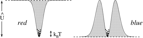
Sign of detuning: Below an atomic resonance (“red” detuning, ) the dipole potential is negative and the interaction thus attracts atoms into the light field. Potential minima are therefore found at positions with maximum intensity. Above resonance (“blue” detuning, ) the dipole interaction repels atoms out of the field, and potential minima correspond to minima of the intensity. According to this distinction, dipole traps can be divided into two main classes, red-detuned traps (Sec. IV) and blue-detuned traps (Sec. V).
-
Scaling with intensity and detuning: The dipole potential scales as , whereas the scattering rate scales as . Therefore, optical dipole traps usually use large detunings and high intensities to keep the scattering rate as low as possible at a certain potential depth.
B Multi-level atoms
In real atoms used for dipole trapping experiments, the electronic transition has a complex sub-structure. The main consequence is that the dipole potential in general depends on the particular sub-state of the atom. This can lead to some quantitative modifications and also interesting new effects. In terms of the oscillator model discussed before, multi-level atoms can be described by state-dependent atomic polarizabilities. Here we use an alternative picture which provides very intuitive insight into the motion of multi-level atoms in far-detuned laser fields: the concept of state-dependent ground-state potentials (Dalibard and Cohen-Tannoudji, 1985, 1989). Alkali atoms are discussed as a situation of great practical importance, in order to clarify the role of fine-structure, hyperfine-structure, and magnetic sub-structure.
1 Ground-state light shifts and optical potentials
The effect of far-detuned laser light on the atomic levels can be treated as a perturbation in second order of the electric field, i.e. linear in terms of the field intensity. As a general result of second-order time-independent perturbation theory for non-degenerate states, an interaction (Hamiltonian ) leads to an energy shift of the -th state (unperturbed energy ) that is given by
| (15) |
For an atom interacting with laser light, the interaction Hamiltonian is with representing the electric dipole operator. For the relevant energies , one has to apply a ‘dressed state’ view (Cohen-Tannoudji et al., 1992), considering the combined system ‘atom plus field’. In its ground state the atom has zero internal energy and the field energy is according to the number of photons. This yields a total energy for the unperturbed state. When the atom is put into an excited state by absorbing a photon, the sum of its internal energy and the field energy becomes . Thus the denominator in Eq. 15 becomes
For a two-level atom, the interaction Hamiltonian is and Eq. 15 simplifies to
| (16) |
for the ground and excited state (upper and lower sign, respectively); we have used the relation , and Eq. 9 to substitute the dipole matrix element with the decay rate . This perturbative result obtained for the energy shifts reveals a very interesting and important fact: The optically induced shift (known as ‘light shift’ or ‘ac Stark shift’) of the ground-state exactly corresponds to the dipole potential for the two-level atom (Eq. 12); the excited state shows the opposite shift. In the interesting case of low saturation, the atom resides most of its time in the ground state and we can interpret the light-shifted ground state as the relevant potential for the motion of atoms. This situation is illustrated in Fig. 1.

For applying Eq. 15 to a multi-level atom with transition substructure***Perturbation theory for non-degenerate states can be applied in the absence of any coupling between degenerate ground states. This is the case for pure linear or circular polarization, but not for mixed polarizations where Raman couplings between different magnetic sub-states become important; see, e.g., Deutsch and Jessen (1997)., one has to know the dipole matrix elements between specific electronic ground states and excited states . It is well-known in atomic physics (see, e.g., Sobelman, 1979) that a specific transition matrix element
| (17) |
can be written as a product of a reduced matrix element and a real transition coefficient . The fully reduced matrix element depends on the electronic orbital wavefunctions only and is directly related to the spontaneous decay rate according to Eq. 9. The coefficients , which take into account the coupling strength between specific sub-levels and of the electronic ground and excited state, depend on the laser polarization and the electronic and nuclear angular momenta involved. They can be calculated in the formalim of irreducible tensor operators or can be found in corresponding tables.
With this reduction of the matrix elements, we can now write the energy shift of an electronic ground state in the form
| (18) |
where the summation is carried out over all electronically excited states . This means, for a calculation of the state-dependent ground-state dipole potential , one has to sum up the contributions of all coupled excited states, taking into account the relevant line strengths and detunings .
2 Alkali atoms
Most experiments in laser cooling and trapping are performed with alkali atoms because of their closed optical transitions lying in a convenient spectral range. The main properties of alkali atoms of relevance for dipole trapping are summarized in Table I. As an example, the full level scheme of the relevant transition is shown in Fig. 2(a) for a nuclear spin , as in the case of 7Li, 23Na, 39, 41K, and 87Rb. Spin-orbit coupling in the excited state (energy splitting ) leads to the well-known line doublet . The coupling to the nuclear spin then produces the hyperfine structure of both ground and excited states with energies and , respectively. The splitting energies, obeying , represent the three relevant atomic energy scales.

On the basis of Eq. 18, one can derive a general result for the potential of a ground state with total angular momentum and magnetic quantum number , which is valid for both linear and circular polarization as long as all optical detunings stay large †††The assumption of unresolved excited-state hyperfine structure greatly simplifies the calculation according to Eq. 18 because of existing sum rules for the line strength coefficients ; see also Deutsch and Jessen (1997). compared with the excited-state hyperfine splitting :
| (19) |
Here is the well-known Landé factor and characterizes the laser polarization ( for linearly and circularly polarized light). The detunings and refer to the energy splitting between the particular ground state 2S and the center of the hyperfine-split 2P3/2 and 2P1/2 excited states, respectively. The two terms in brackets of Eq. 19 thus represent the contributions of the and the line to the total dipole potential.
In order to discuss this result, let us first consider the case of very large detunings greatly exceeding the fine-structure splitting (), in which we can completely neglect the even much smaller hyperfine splitting. Introducing a detuning with respect to the center of the -line dublett, we can linearly expand Eq. 19 in terms of the small parameter :
| (20) |
While the first-order term describes a small residual dependence on the polarization and the magnetic sub-state , the dominating zero-order term is just the result obtained for a two-level atom (Eq. 12). The latter fact can be understood by a simple argument: If the fine-structure is not resolved, then the detuning represents the leading term in the total Hamiltonian and the atomic sub-structure can be ignored in a first perturbative step by reducing the atom to a very simple transition; see Fig. 2(b). Such a transition behaves like a two-level atom with the full line strength for any laser polarization, and the ground-state light shift is thus equal to the one of a two-level atom. This single ground state couples to the electronic and nuclear spin in exactly the same way as it would do without the light. In this simple case, all resulting hyperfine and magnetic substates states directly acquire the light shift of the initial atomic state.
In the more general case of a resolved fine-structure, but unresolved hyperfine structure (), one may first consider the atom in spin-orbit coupling, neglecting the coupling to the nuclear spin. The interaction with the laser field can thus be considered in the electronic angular momentum configuration of the two lines, . In this situation, illustrated in Fig. 2(c), one can first calculate the light shifts of the two electronic ground states , and in a later step consider their coupling to the nuclear spin. In this situation, it is important to distinguish between linearly and circularly polarized light:
For linear polarization, both electronic ground states () are shifted by the same amount because of simple symmetry reasons. After coupling to the nuclear spin, the resulting states have to remain degenerate like the two original states. Consequently, all magnetic sublevels show the same light shifts according to the line strength factors of for the line and for the line.
For circular polarization (), the light lifts the degeneracy of the two magnetic sublevels of the electronic 2S ground state, and the situation gets more complicated. The relevant line strength factors are then given by for the line and for the line. The lifted degeneracy of the two ground states can be interpreted in terms of a ‘fictitous magnetic field’ (Cohen-Tannoudji and Dupont-Roc, 1972; Cho, 1997; Zielonkowski et al., 1998a), which is very useful to understand how the lifted degeneracy affects the levels after coupling to the nuclear spin. According to the usual theory of the linear Zeeman effect in weak magnetic fields, coupling to the nuclear spin affects the magnetic sub-structure such that one has to replace by , with and denoting the ground state Landé factors. Using this analogy and for alkali atoms, we can substitute by to calculate the relevant line strength factors and for the and the line, respectively. These factors lead to the dependent shifts for circularly polarized light in Eq. 19. One finds that this result stays valid as long as the excited-state hyperfine splitting remains unresolved.
For the photon scattering rate of a multi-level atom, the same line strength factors are relevant as for the dipole potential, since absorption and light shifts are determined by the same transititon matrix elements. For linear polarization, in the most general case considered here, one thus explicitely obtains
| (21) |
This result is independent of , but in general depends on the hyperfine state via the detunings. For linearly polarized light, optical pumping tends to equally distribute the population among the different states, and thus leads to complete depolarization. If the detuning is large compared to the ground-state hyperfine splitting, then all sub-states are equally populated by redistribution via photon scattering. For circular polarization, Zeeman pumping effects become very important, which depend on the particular detuning regime and which we do not want to discuss in more detail here. It is interesting to note that the general relation between dipole potential and scattering rate takes the simple form of Eq. 14 either if the contribution of one of the two lines dominates for rather small detunings or if the detuning is large compared to the fine-structure splitting.
Our discussion on multi-level alkali atoms shows that linearly polarized light is usually the right choice for a dipole trap‡‡‡an interesting exception is the work by Corwin et al. (1997) on trapping in circularly polarized light; see also Sec. IV A 2., because the magnetic sub-levels of a certain hyperfine ground-state are shifted by same amounts. This only requires a detuning large compared to the excited-state hyperfine splitting, which is usually very well fulfilled in dipole trapping experiments. If the detuning also exceeds the ground-state hyperfine splitting then all sub-states of the electronic ground state are equally shifted, and the dipole potential becomes completely independent of and . For circularly polarized light there is a -dependent contribution, which leads to a splitting analogous to a magnetic field. This term vanishes only if the optical detuning greatly exceeds the fine-structure splitting.
III Experimental issues
Here we discuss several issues of practical importance for experiments on dipole trapping. Cooling and heating in the trap is considered in Sec. III A, followed by a summary of the typical experimental procedures in Sec. III B. Finally, the particular role of collisions is discussed in Sec. III C.
A Cooling and heating
Atom trapping in dipole potentials requires cooling to load the trap and eventually also to counteract heating in the dipole trap. We briefly review the various available cooling methods and their specific features with respect to dipole trapping. Then we discuss sources of heating, and we derive explicite expressions for the heating rate in the case of thermal equilibrium in a dipole trap. This allows for a direct comparison between dipole traps operating with red and blue detuning.
1 Cooling methods
Efficient cooling techniques are an essential requirement to load atoms into a dipole trap since the attainable trap depths are generally below 1 mK. Once trapped, further cooling can be applied to achieve high phase-space densities and to compensate possible heating mechanisms (see Sec. III A 2) which would otherwise boil the atoms out of the trap. The development of cooling methods for neutral atoms has proceeded at breathtaking speed during the last decade, and numerous excellent reviews have been written illuminating these developments (Foot, 1991; Arimondo et al., 1992; Metcalf and van der Straten, 1994; Sengstock and Ertmer, 1995; Ketterle and van Druten, 1996; Adams and Riis, 1997; Chu, 1998; Cohen-Tannoudji, 1998; Phillips, 1998). In this section, we briefly discuss methods which are of relevance for cooling atoms in dipole traps. Chapters IV and V describe the experimental implementations of the cooling schemes to particular trap configurations.
Doppler cooling.
Doppler cooling is based on cycles of near-resonant absorption of a photon and subsequent spontaneous emission resulting in a net atomic momentum change per cycle of one photon momentum with denoting the wavenumber of the absorbed photon. Cooling is counteracted by heating due to the momentum fluctuations by the recoil of the spontaneously emitted photons (Minogin and Letokhov, 1987). Equilibrium between cooling and heating determines the lowest achievable temperature. For Doppler cooling of two-level atoms in standing waves (“optical molasses”), the minimum temperature is given by the Doppler temperature . Typical values of the Doppler temperature are around K, which is just sufficiently low to load atoms into a deep dipole trap. The first demonstration of dipole trapping (Chu et al., 1986) used Doppler cooling for loading the trap and keeping the atoms from being boiled out of the trap. With the discovery of methods reaching much lower temperatures, Doppler cooling has lost its importance for the direct application to dipole traps.
Polarization-gradient cooling.
The Doppler temperature is a somewhat artificial limit since it is based on the simplifying assumption of a two-level atom. It was soon discovered that atoms with a more complex level structure can be cooled below in standing waves with spatially varying polarizations (Lett et al., 1988). The cooling mechanisms are based on optical pumping between ground state Zeeman sublevels. The friction force providing cooling results either from unbalanced radiation pressures through motion-induced atomic orientation, or from a redistribution among the photons in the standing wave (Dalibard and Cohen-Tannoudji, 1989). In the latter case, the cooling force can be illustratively explained by the so-called Sisyphus effect for a moving atom. The atom looses kinetic energy by climbing up the dipole potential induced by the standing wave of the trapping light. When reaching the top of this potential hill, the atom is optically pumped back into the bottom of the next potential valley from where again it starts to climb (Dalibard and Cohen-Tannoudji, 1985). Polarization-gradient cooling can be achieved in standing waves at frequencies below an atomic resonance (red-detuned molasses) (Lett et al., 1988; Salomon et al., 1990) as well as above an atomic resonance (blue-detuned molasses) (Boiron et al., 1995; Hemmerich et al., 1995). In blue-detuned molasses, atoms primarily populate states which are decoupled from the light field resulting in a reduction of photon scattering, but also in a smaller cooling rate as compared to red-detuned molasses (Boiron et al., 1996).
With polarization-gradient molasses one can prepare free-space atomic samples at temperatures on the order of with the recoil temperature
| (22) |
being defined as the temperature associated with the kinetic energy gain by emission of one photon. For the alkali atoms, recoil temperatures are given in Table I. The achievable temperatures are much below the typical depth of a dipole trap. Polarization-gradient cooling therefore allows efficient loading of dipole traps (see Sec. III B 1), either by cooling inside a magneto-optical trap (Steane and Foot, 1991) or by cooling in a short molasses phase before transfer into the dipole trap.
Besides enhancing the loading efficiency, polarization-gradient cooling was directly applied to atoms trapped in a dipole potential by subjecting them to near-resonant standing waves with polarization gradients (Boiron et al., 1998; Winoto et al., 1998). Since the cooling mechanism relies on the modification of the ground-state sublevels by the cooling light, a necessary condition for efficient cooling is the independency of the trapping potential from the Zeeman substate which, in contrast to magnetic traps, can easily be fulfilled in dipole traps as explained in Sec. II B 2.
Raman cooling.
The recoil temperature marks the limit for cooling methods based on the repeated absorption and emission of photons such as Doppler cooling and polarization-gradient cooling. To overcome this limit, different routes were explored to decouple the cold atoms from the resonant laser excitation once they have reached small velocities. All approaches are based upon transitions with a narrow line width which are thus extremely velocity-selective such as dark-state resonances (Aspect et al., 1988) or Raman transition between ground state sublevels (Kasevich and Chu, 1992). With free atomic samples, the interaction time, and thus the spectral resolution determining the final temperature, was limited by the time the thermally expanding atomic cloud spent in the laser field (Davidson et al., 1994). Taking advantage of the long storage times in dipole traps, Raman cooling was shown to efficiently work for trapped atomic samples (Lee et al., 1994; Lee et al., 1996; Kuhn et al., 1996).
The basic principle of Raman cooling is the following. Raman pulses from two counter-propagating laser beams transfer atoms from one ground state to another ground state transferring momentum §§§The two states are, e.g., the two hyperfine ground states of an alkali atom.. Using sequences of Raman pulses with varying frequency width, detuning, and propagation direction, pulses can be tailored which excite all atoms except those with a velocity near (Kasevich et al., 1992; Reichel et al., 1995; Kuhn et al., 1996). The cooling cycle is completed by a light pulse resonantly exciting atoms in state in order to optically pump the atoms back to the state through spontaneous emission. Each spontaneous emission randomizes the velocity distribution so that a fraction of atoms will acquire a velocity . By repeating many sequences of Raman pulses followed by optical pumping pulses, atoms are accumulated in a small velocity interval around . The final width of the velocity distribution, i.e. the temperature, is determined by the spectral resolution of the Raman pulses. In dipole traps, high resolution can be achieved by the long storage times. In addition, motional coupling of the degrees of freedom through the trap potential allowed to cool the atomic motion in all three dimensions with Raman pulses applied along only one spatial direction (Lee et al., 1996; Kuhn et al., 1996).
Resolved-sideband Raman cooling.
Cooling with well-resolved motional sidebands, a technique well known from laser cooling in ion traps (Ghosh, 1995), was very recently also applied to optical dipole traps (Hamann et al., 1998; Perrin et al., 1998; Vuletic et al., 1998; Bouchoule et al.; 1998). For resolved-sideband cooling, atoms must be tightly confined along (at least) one spatial dimension with oscillation frequencies large enough to be resolved by Raman transitions between two ground state levels. In contrast to Raman cooling explained in the preceeding paragraph, the confining potential of the trap is therefore a necessary prerequisite for the application of sideband cooling.
Atomic motion in the tightly confining potential is described by a wavepacket formed by the superposition of vibrational states . In the Lamb-Dicke regime, where the rms size of the wavepacket is small compared to the wavelength of the cooling transition, an absorption-spontaneous emission cycle almost exclusively returns to the same vibrational state it started from (). The Lamb-Dicke regime is reached by trapping atoms in dipole potentials formed in the interference pattern of far-detuned laser beams (see Secs. IV B and IV C). Sideband cooling consists of repeated cycles of Raman pulses which are tuned to excite transitions with followed by an optical pumping pulse involving spontaneous emission back to the initial state with . In this way, the motional ground state is selectively populated since it is the only state not interacting with the Raman pulses. Achievable temperatures are only limited by the separation and the width of the Raman sidebands determining the suppression of off-resonant excitation of the state.
A particularly elegant realization of sideband cooling was accomplished by using the trapping light itself to drive the Raman transition instead of applying additional laser fields (Hamann et al, 1998; Vuletic et al., 1998). For this purpose, a small magnetic field was applied shifting the energy of two adjacent ground-state Zeeman sublevels relative to each other by exactly one vibrational quantum . In this way, the bound states and became degenerate, and Raman transitions between the two states could be excited with single-frequency light provided by the trapping field (degenerate sideband cooling) (Deutsch and Jessen, 1998). The great advantage of degenerate sideband cooling is that works with only the two lowest-energy atomic ground states being involved, resulting in the suppression of heating and trap losses caused by inelastic binary collisions (see Sec. III C).
Evaporative cooling.
Evaporative cooling, orginally demonstated with magnetically trapped hydrogen (Hess et al., 1987), has been the key technique to achieve Bose-Einstein condensation in magnetic traps (Ketterle and van Druten, 1996). It relies on the selective removal of high-energetic particles from a trap and subsequent thermalization of the remaining particles through elastic collisions. Evaporative cooling requires high densities to assure fast thermalization rates, and large initial particle numbers since a large fraction of trapped atoms is removed from the trap by evaporation. To become effective, the ratio between inelastic collisions causing losses and heating, and elastic collisions providing thermalization and evaporation, has to be large.
In dipole traps, inelastic processes can be greatly suppressed when the particles are prepared in their energetically lowest state. However, the requirement of large particle numbers and high density poses a dilemma for the application of evaporative cooling to dipole traps. In tightly confining dipole traps such as a crossed dipole trap, high peak densities can be reached, but the trapping volume, and thus the number of particles transferred into the trap, is small. On the other hand, large trapping volumes yielding large numbers of trapped particles provide only weak confinement yielding small elastic collision rates. This is why, until now, only one experiment is reported on evaporative cooling in dipole traps starting with a small sample of atoms (Adams et al., 1995). By precooling large ensembles in dipole traps with optical methods explained in the preceeding paragraphs, much better starting conditions for evaporative cooling are achievable (Engler et al., 1998; Vuletic et al., 1998; Winoto et al., 1998) making evaporative cooling a still interesting option for future applications.
Adiabatic expansion.
When adiabatically expanding a potential without changing its shape, the temperature of the confined atoms is decreased without increasing the phase-space density ¶¶¶Adiabatic changes of the potential shape leading to an increase of the phase-space density are demonstrated in (Pinkse et al., 1997) and (Stamper-Kurn et al., 1998b).. In dipole potentials, cooling by adiabatic expansion was realized by slowly ramping down the trapping light intensity (Chen et al., 1992; Kastberg et al., 1995). In far-detuned traps consisting of micropotentials induced by interference, adiabatic cooling is particularly interesting when the modulation on the scale of the optical wavelength is slowly reduced without modifying the large-scale trapping potential, by, e.g. changing the polarization of the interfering laser beams. Atoms are initially strongly localized in the micropotentials resulting in high peak densities. After adiabatic expansion, the temperature of the sample is reduced, as is the peak density. However, the density averaged over one period of the interference structure is not modified.
2 Heating mechanisms
Heating by the trap light is an issue of particular importance for optical dipole trapping. A fundamental source of heating is the spontaneous scattering of trap photons, which due to its random nature causes fluctuations of the radiation force∥∥∥Under typical conditions of a dipole trap, the scattering force that results in traveling-wave configurations stays very weak as compared to the dipole force and can thus be neglected.. In the far-detuned case considered here, the scattering is completely elastic (or quasi-elastic if a Raman process changes the atomic ground state). This means that the energy of the scattered photon is determined by the frequency of the laser and not of the optical transition.
Both absorption and spontaneous re-emission processes show fluctuations and thus both contribute to the total heating (Minogin and Letokhov, 1987). At large detunings, where scattering processes follow Poisson statistics, the heating due to fluctuations in absorption corresponds to an increase of the thermal energy by exactly the recoil energy per scattering event. This first contribution occurs in the propagation direction of the light field and is thus anisotropic (so-called directional diffusion). The second contribution is due to the random direction of the photon recoil in spontaneous emission. This heating also increases the thermal energy by one recoil energy per scattering event, but distributed over all three dimensions. Neglecting the general dependence on the polarization of the spontaneously emitted photons, one can assume an isotropic distribution for this heating mechanism. Taking into account both contributions, the longitudinal motion is heated on an average by per scattering process, whereas the two transverse dimensions are each heated by . The overall heating thus corresponds to an increase of the total thermal energy by in a time .
For simplicity, we do not consider the generally anisotropic character of heating here; in most cases of interest the trap anyway mixes the motional degrees on a time scale faster than or comparable to the heating. We can thus use a simple global three-dimensional heating power corresponding to the increase of the mean thermal energy of the atomic motion with time. This heating power is directly related to the average photon scattering rate by
| (23) |
For intense light fields close to resonance, in particular in standing-wave configurations, it is well known that the induced redistribution of photons between different traveling-wave components can lead to dramatic heating (Gordon and Ashkin, 1980; Dalibard and Cohen-Tannoudji, 1985). In the far off-resonant case, however, this induced heating falls off very rapidly with the detuning and is usually completely negligible as compared to spontaneous heating.
In addition to the discussed fundamental heating in dipole traps, it was recently pointed out by Savard et al. (1997), that technical heating can occur due to intensity fluctuations and pointing instabilities in the trapping fields. In the first case, fluctuations occuring at twice the characteristic trap frequencies are relevant, as they can parametrically drive the oscillatory atomic motion. In the second case, a shaking of the potential at the trap frequencies increases the motional amplitude. Experimentally, these issues will strongly depend on the particular laser source and its technical noise spectrum, but have not been studied in detail yet. Several experiments have indeed shown indications for heating in dipole traps by unidentified mechanisms (Adams et al., 1995; Lee et al., 1996; Zielonkowski et al., 1998b; Vuletic et al., 1998), which may have to do with fluctuations of the trapping light.
3 Heating rate
For an ultracold atomic gas in a dipole trap it is often a good assumption to consider a thermal equilibrium situation, in which the energy distribution is related to a temperature . The further assumption of a power-law potential then allows one to derive very useful expressions for the mean photon scattering rate and the corresponding heating rate of the ensemble, which also illustrate important differences between traps operating with red and blue detuned light.
In thermal equilibrium, the mean kinetic energy per atom in a three-dimensional trap is . Introducing the parameter as the ratio of potential and kinetic energy, we can express the mean total energy as
| (24) |
For many real dipole traps as described in Secs. IV and V, it is a good approximation to assume a separable power-law potential with a constant offset of the form
| (25) |
In such a case, the virial theorem can be used to calculate the ratio between potential and kinetic energy
| (26) |
For a 3D harmonic trap this gives , for an ideal 3D box potential .
The relation between mean energy and temperature (Eq. 24) allows us to reexpress the heating power resulting from photon scattering (Eq. 23) as a heating rate
| (27) |
describing the corresponding increase of temperature with time.
The mean scattering rate can, in turn, be calculated from the temperature of the sample, according to the following arguments: Eq. 14 relates the average scattering rate to the mean dipole potential experienced by the atoms. In a pure dipole trap******this excludes hybrid potentials in which other fields (gravity, magnetic or electric fields) are important for the trapping. described by Eq. 25, the mean optical potential is related to the mean potential energy , the mean kinetic energy , and the temperature by
| (28) |
This relation allows us to express the mean scattering rate as
| (29) |
Based on this result, let us now discuss two specific situations which are typical for real experiments as described in Secs. IV and V; see illustrations in Fig. 3. In a red-detuned dipole trap (), the atoms are trapped in an intensity maximum with , and the trap depth is usually large compared to the thermal energy . In a blue-detuned trap (), a potential minimum corresponds to an intensity minimum, which in an ideal case means zero intensity. In this case, and the potential depth is determined by the height of the repulsive walls surrounding the center of the trap.
For red and blue-detuned traps with , Eqs. 27 and 29 yield the following heating rates:
| (31) | |||||
| (32) |
Obviously, a red-detuned trap shows linear heating (which decreases when approaches ), whereas heating behaves exponentially in a blue-detuned trap. Note that in blue-detuned traps a fundamental lower limit to heating is set by the zero-point energy of the atomic motion, which we have neglected in our classical consideration.
Eqs. III A 3 allow for a very illustrative direct comparison between a blue and a red-detuned trap: The ratio of heating at the same magnitude of detuning is given by
| (33) |
This comparison shows that blue detuning offers substantial advantages in two experimental situations:
-
, very deep potentials for tight confinement,
-
, box-like potentials with hard repulsive walls.
When, in other words, a harmonic potential of moderate depth is to be realized for a certain experiment, the advantage of blue detuning is not substantial. The choice of red detuning may be even more appropriate as the better concentration of the available laser power in such a trap allows one to use larger detunings to create the required potential depth.
B Experimental techniques
1 Trap loading
The standard way to load a dipole trap is to start from a magneto-optical trap (MOT). This well-known radiation-pressure trap operating with near-resonant light was first demonstrated by Raab et al. in 1987 and has now become the standard source of ultracold atoms in many laboratories all over the world. A MOT can provide temperatures down to a few 10 , when its operation is optimized for sub-Doppler cooling (see Sec. III A 1). This sets a natural scale for the minimum depth of a dipole trap as required for efficient loading. Due to their lower recoil temperatures (Table I), heavier alkali atoms require less trap depth as the lighter ones and thus allow for larger detunings. For the heavy Cs atoms, for example, dipole traps with depths as low as 10 K can be directly loaded from a MOT (Zielonkowski et al., 1998b). Trap loading at much lower depths can be reached with Bose-Einstein condensates (Stamper-Kurn et al., 1998).
For dipole-trap loading, a MOT is typically operated in two stages. First, its frequency detuning is set quite close to resonance (detuning of a few natural linewidths) to optimize capture by the resonant scattering force. Then, after the loading phase, the MOT parameters are changed to optimize sub-Doppler cooling (Drewsen et al., 1994; Townsend et al., 1995). Most importantly, the detuning is switched to much higher values (typically 10 – 20 linewidths), and eventually also the laser intensity is lowered. For the heavier alkali atoms††††††The lightest alkali atom Li behaves in a completely different way: Here optimum loading is accomplished at larger detunings and optimum cooling is obtained relatively close to resonance (Schünemann et al., 1998), this procedure provides maximum phase-space densities for trap loading. Another option is to ramp up the magnetic fields of the MOT to spatially compress the sample (Petrich et al., 1994).
The dipole trap is filled by simply overlapping it with the atomic cloud in the MOT, before the latter is turned off. In this procedure, it is advantageous to switch off the magnetic field of the MOT a few ms before the laser fields are extinguished, because the short resulting optical molasses cooling phase establishes the lowest possible temperatures and a quasi-thermal distribution in the trap. For practical reasons, the latter is important because a MOT does not necessarily load the atoms into the very center of the dipole trap. When MOT position and dipole trap center do not coincide exactly, loading results in excess potential energy in the dipole trap. When the MOT light is extinguished, it is very important to shield the dipole trap from any resonant stray light, in particular if very low scattering rates ( 1 s-1) are to be reached.
The MOT itself can be loaded in a simple vapor cell (Monroe et al., 1990). In such a set-up, however, the lifetime of the dipole trap is typically limited to less than 1 s by collsions with atoms in the background gas. If longer lifetimes are requested for a certain application, the loading of the MOT under much better vacuum conditions becomes an important issue, similar to experiments on Bose-Einstein condensation. Loading can then be accomplished from a very dilute vapor (Anderson et al., 1994), but more powerful concepts can be realized with a Zeeman-slowed atomic beam (Phillips and Metcalf, 1982), with a double-MOT set-up (Myatt et al., 1997), or with slow-atom sources based on modified MOTs (Lu et al., 1996, Dieckmann et al., 1998).
Regarding trap loading, a dipole trap with red detuning can offer an important advantage over a blue-detuned trap: When MOT and dipole trap are simultaneously turned on, the attractive dipole potential leads to a local density increase in the MOT, which can substantially enhance the loading process. In very deep red-detuned traps, however, the level shifts become too large for the cooling light and efficient loading requires rapid alternation between cooling and trapping light (Miller et al., 1993).
2 Diagnostics
The atomic sample in a dipole trap is characterized by the number of stored atoms, the motional temperature of the ensemble (under the assumption of thermal distribution), and the distribution of population among the different ground-state sub-levels. Measurements of these important quantities can be made in the following ways.
Number of atoms.
A very simple and efficient method, which is often used to determine the number of atoms in a dipole trap is to recapture them into the MOT and to measure the power of the emitted fluorescence light with a calibrated photo-diode or CCD camera. In this way, it is quite easy to detect down to about one hundred atoms, but even single atoms may be observed in a more elaborate set-up (Haubrich et al., 1996). This recapture method works particularly well if it is ensured that the MOT does not capture any other atoms than those released from the dipole trap. This is hardly possible in a simple vapor-cell set-up, but quite easy if an atomic beam equipped with a mechanical shutter is used for loading the MOT.
In contrast to the completely destructive recapture, several other methods may be applied. The trapped atoms can be illuminated with a short resonant laser pulse of moderate intensity to measure the emitted fluorescence light. This can be done also with spatial resolution by using a CCD camera; see Fig. 18(b) for an example. If the total number of atoms is not too low, the detection pulse can be kept weak enough to avoid trap loss by heating. Furthermore, absorption imaging can be used (see Fig. 7), or even more sensitive and less destructive dark-field or phase-contrast imaging methods as applied to sensitively monitor Bose-Einstein condensates (Andrews et al., 1996; Bradley et al., 1997; Andrews et al., 1997).
Temperature.
In a given trapping potential the thermal density distribution direct follows from the Boltzmann factor,
| (34) |
The temperature can thus be derived from the measured spatial density distribution in the trap, which itself can be observed by various imaging methods (fluorescence, absorptive, and dispersive imaging). For a 3D harmonic potential the resulting distribution is Gaussian in all directions,
| (35) |
with . The temperature is thus related to the spatial extensions of the trapped atom cloud by
| (36) |
Obviously, it is very important to know the exact trap frequencies to precisely determine the temperature; a practical example for such a measurement is discussed in context with Fig. 7(c). This way of measuring the temperature is limited by the resolution of the imaging system and therefore becomes difficult for very tightly confining potentials.
A widely used and quite accurate, but completely destructive way to measure temperatures is the time-of-flight method. The trap is turned off to release the atoms into a free, ballistic flight. This has to be done in a rapid, completely non-adiabatic way as otherwise an adiabatic cooling effect (see Sec. III A 1) would influence the measurement. After a sufficiently long ballistic expansion phase, the resulting spatial distribution, which can again be observed by the various imaging methods, directly reflects the velocity distribution at the time of release. Another method is to detect the Doppler broadening of Raman transitions between ground states, using a pair of counterpropagating laser beams (Kasevich and Chu, 1991), which is not limited by the natural linewidth of the optical transition.
Internal distribution.
The relative population of the two hyperfine ground states of an alkali atom (see level scheme in Fig. 2) can be measured by application of a probe pulse resonant to the closed sub-transition in the hyperfine structure, which is well resolved for the heavier alkali atoms (see Table I). The fluorescence light is then proportional to the number of atoms in the upper hyperfine state . If, in contrast, a repumping field is present in the probe light (as it is always used in a MOT), the fluorescence is proportional to the total number of atoms, as all atoms are immediately pumped into the closed excitation cycle. The normalized fluorescence signal thus gives the relative population of the upper hyperfine ground state (); such a measurement is discussed in Sec. IV A 2. A very sensitive alternative, which works very well in shallow dipole traps, is to blow the total upper-state population out of the trap by the radiation pressure of an appropriate resonant light pulse. Subsequent recapture into the MOT then shows how many atoms have remained trapped in the shelved lower hyperfine ground state.
The distribution of population over different magnetic sub-states can be analyzed by Stern-Gerlach methods. When the atomic ensemble is released from the dipole trap and ballistically expands in an inhomogeneous magnetic field, then atoms in different magnetic sub-levels can be well separated in space. Such an analysis has been used for optically trapped Bose-Einstein condensates (Stamper-Kurn et al., 1998a; Stenger, 1998); an example is shown in Fig. 8(b). Another possibility, which can be easily applied to shallow dipole traps, is to pull atoms out of the trap by the state-dependent magnetic force, as has been used by Zielonkowski et al. (1998b) for measuring the depolarizing effect of the trap photon scattering; see discussion in Sec. IV B 3.
C Collisions
It is a well-known experimental fact in the field of laser cooling and trapping that collisional processes can lead to substantial trap loss. Detailed measurements of trap loss under various conditions provide insight into ultracold collision phenomena, which have been subject of extensive research (Walker and Feng, 1994; Weiner, 1995). Here we discuss the particular features of dipole traps with respect to ultracold collisions.
The decay of the number of atoms in a trap can be described by the general loss equation
| (37) |
Here the single-particle loss coefficient takes into account collisions with the background gas in the vacuum apparatus. As a rule of thumb, the lifetime of a dipole trap is 1 s at a pressure of mbar. This is about three times lower than the corresponding lifetime in a MOT because of the larger cross sections for collisional loss at lower trap depth.
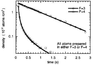
The two-body loss coefficient describes trap loss due to ultracold binary collisions and reveals a wide range of interesting physics. In general, such trap loss becomes important if the colliding atoms are not in their absolute ground state. In an inelastic process the internal energy can be released into the atomic motion, causing escape from the trap. Due to the shallowness of optical dipole traps, even the collisional release of the relatively small amount of energy in the ground-state hyperfine structure of an alkali atom will always lead to trap loss‡‡‡‡‡‡In contrast, a MOT operated under optimum capture conditions is deep enough to hold atoms after hyperfine-changing collisions.. Hyperfine-changing collisions, which occur with large rate coefficients of typically cm3/s (Sesko et al., 1989; Wallace et al., 1992), are thus of particular importance for dipole trapping. Alkali atoms in the upper hyperfine state () can show very rapid, non-exponential collisional decay, in contrast to a sample in the lower ground state (). This is impressively demonstrated by the measurement in Fig. 4, which shows the decay of a sample of Cs atoms prepared either in the upper or lower hyperfine ground state. For the implementaion of laser cooling schemes in dipole traps, it is thus a very important issue to keep the atoms predominantly in the lower hyperfine state; several schemes fulfilling this requirement are discussed in Secs. IV and V.
Trap loss can also occur as a result of light-assisted binary collisions involving atoms in the excited state. The radiative escape mechanism (Gallagher and Pritchard, 1989) and excited-state fine-structure changing collisions strongly affect a MOT, but their influence is negligibly small in a dipole trap because of the extremely low optical excitation. It can become important, however, if near-resonant cooling light is present. Another important mechanism for trap loss is photoassociation (Lett et al., 1995), a process in which colliding atoms are excited to bound molecular states, which then decay via bound-bound or bound-free transitions. Dipole traps indeed represent a powerful tool for photoassociative spectroscopy (Miller et al., 1993b).
Three-body losses, as described by the coefficient in Eq. 37, become relevant only at extremely high densities (Burt et al., 1997; Stamper-Kurn et al., 1998a), far exceeding the conditions of a MOT. In a collision of three atoms, a bound dimer can be formed and the third atom takes up the released energy, so that all three atoms are lost from the trap. As a far-detuned dipole trap allows one to completely suppress binary collision losses by putting the atoms into the absolute internal ground state, it represents an interesting tool for measurements on three-body collisions; an example is discussed in Sec. IV A 4.
In contrast to inelastic collisions releasing energy, elastic collisions lead to a thermalization of the trapped atomic ensemble. This also produces a few atoms with energies substantially exceeding . A loss of these energetic atoms in a shallow trap leads to evaporative cooling (see Sec. III A 1) and is thus of great interest for the attainment of Bose-Einstein condensation. Regarding the basic physics of elastic collisions, dipole traps are not different from magnetic traps, but they offer additional experimental possibilities. By application of a homogeneous magnetic field atomic scattering properties can be tuned without affecting the trapping itself. Using this advantage of dipole trapping, Feshbach resonances have been observed with Bose-condensed Na atoms (Inouye et al., 1998) and thermal Rb atoms (Courteille et al., 1998). Moreover, an intriguing possibility is to study collisions in an arbitrary mixture of atoms in different magnetic sub-states (Stenger et al., 1998).
IV Red-detuned dipole traps
The dipole force points towards increasing intensity if the light field is tuned below the atomic transition frequency (red detuning). Therefore, already the focus of a laser beam constitutes a stable dipole trap for atoms as first proposed by Ashkin (1978). The trapping forces generated by intense focused lasers are rather feeble which was thhe main obstacle for trapping neutral atoms in dipole traps. Attainable trap depths in a tightly focused beam are typically in the millikelvin range, orders of magnitude smaller than the thermal energy of room-temperature atoms. One therefore had to first develop efficient laser cooling methods for the preparation of cold atom sources (see Sec. III A 1) to transfer significant numbers of atoms into a dipole trap.
In their decisive experiment, S. Chu and coworkers (1986) succeeded in holding about 500 sodium atoms for several seconds in the tight focus of a red-detuned laser beam. Doppler molasses cooling was used to load atoms into the trap, which was operated at high intensities and considerable atomic excitation in order to provide a sufficiently deep trapping potential. Under these circumstances, the radiation pressure force still significantly influences the trapping potential due to a considerable rate of spontaneous emission. With the development of sub-Doppler cooling (see Sec. III A 1) and the invention of the magneto-optical trap as a source for dense, cold atomic samples (see Sec. III B 1), dipole trapping of atoms regained attention with the demonstration of a far-off resonant trap by Miller et al. (1993). In such a trap, spontaneous emission of photons is negligible, and the trapping potential is given by from the equations derived in Sec. II.
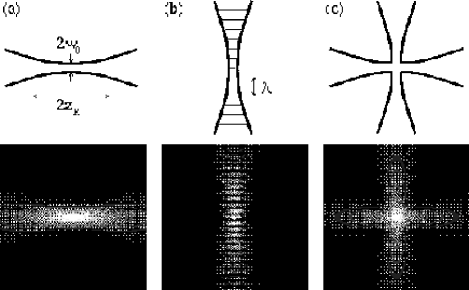
Since then, three major trap types with red-detuned laser beams have been established, all based on combinations of focused Gaussian beams: Focused-beam traps consisting of a single beam, the standing-wave traps where atoms are axially confined in the antinodes of a standing wave, and crossed-beam traps created by of two or more beams intersecting at their foci. The different trap types are schmetically depicted in Fig. 5. We discuss these trap configurations and review applications of the different trap types for the investigation of interesting physical questions. Sec. IV A deals with focused-beam traps, Sec. IV B presents standing-wave traps, and Sec. IV C discusses crossed-beam traps. Far-detuned optical lattices trapping atoms in micropotentials formed by multiple-beam interference represent a trap class of their own. Atoms might get trapped in the antinodes of the interference pattern at red detuning from resonance, but also in the nodes when the light field is blue-detuned. Sec. IV D at the end of this chapter is devoted to recent developments on far-detuned optical lattices.
A Focused-beam traps
A focused Gaussian laser beam tuned far below the atomic resonance frequency represents the simplest way to create a dipole trap providing three-dimensional confinement [see Fig. 5(a)]. The spatial intensity distribution of a focused Gaussian beam (FB) with power propagating along the -axis is described by
| (38) |
where denotes the radial coordinate. The radius depends on the axial coordinate via
| (39) |
where the minimum radius is called the beam waist and denotes the Rayleigh length. From the intensity distribution one can derive the optical potential using Eq. 10, 12, or 19. The trap depth is given by .
The Rayleigh length is larger than the beam waist by a factor of . Therefore the potential in the radial direction is much steeper than in the axial direction. To provide stable trapping one has to ensure that the gravitational force does not exceed the confining dipole force. Focused-beam traps are therefore mostly aligned along the horizontal axis. In this case, the strong radial force minimizes the perturbing effects of gravity ******A new type of trap for the compensation of gravity was presented by Lemonde et al. (1995). It combines a focused-beam dipole trap providing radial confinement with an inhomogeneous static electric field along the vertical -axis inducing tight axial confinement through the dc Stark effekt..
If the thermal energy of an atomic ensemble is much smaller than the potential depth , the extension of the atomic sample is radially small compared to the beam waist and axially small compared to the Rayleigh range. In this case, the optical potential can be well approximated by a simple cylindrically symmetric harmonic oscillator
| (40) |
The oscillation frequencies of a trapped atom are given by in the radial direction, and in the axial direction. According to Eq. 25, the harmonic potential represents an important special case of a power law potential for which thermal equilibrium properties are discussed in Sec. III.
1 Collisional studies
In their pioneering work on far-off resonance traps (FORT), Miller et al. (1993a) from the group at University of Texas in Austin have observed trapping of 85Rb atoms in the focus of a single, linearly polarized Gaussian beam with detunings from the resonance of up to nm. The laser beam was focused to a waist of m creating trap depths in the mK-range for detunings. Between and atoms were accumulated in the trap from atoms provided by a vapor-cell MOT. Small transfer efficiencies are a general property of traps with tightly focused beams resulting from the small spatial overlap between the cloud of atoms in the MOT. Typical temperatures in the trap are below 1 mK resulting in densities close to atoms/cm3. Peak photon scattering rates were a few hundreds per second leading to negligible loss rates by photon heating as compared to losses by background gas collisions. High densities achieved in a tightly-focused beam in combination with long storage times offer ideal conditions for the investigation of collisions between trapped atoms.
The trap lifetime without cooling illustrated in Fig. 6(a) showed an increase of the lifetime by about an order of magnitude for increasing detunings at rather small detunings. At larger detunings, the lifetime was found to be determined by the Rb background pressure of the vapor-cell to a value of about 200 ms. The shorter lifetimes at smaller detunings were explained in a later publication (Miller et al., 1993b) by losses through photoassociation of excited Rb2 dimers which was induced by the trapping light. This important discovery has inspired a whole series of experiments on ultracold collisions investigated by the Austin group with photoassociation spectroscopy in a dipole trap. Instead of using the trapping light, photoassociation was induced by additional lasers in later experiments. The investigations comprise collisional properties and long-range interaction potentials of ground state atoms, shape resonances in cold collisions, and the observation of Feshbach resonances (Cline et al., 1994b; Gardner et al., 1995; Boesten et al., 1996; Tsai et al., 1997, Courteille et al., 1998).
2 Spin relaxation
If the detuning of the trapping light field is larger than finestructure splitting of the excited state, photon scattering occurs almost exclusively into the elastic Rayleigh component. Inelastic Raman scattering changing the hyperfine ground state is reduced by a factor as compared to Rayleigh scattering. This effect was demonstrated in the Austin group by preparing all trapped 85Rb atoms in the lower hyperfine ground state and studying the temporal evolution of the higher hyperfine state (Cline et al., 1994a). The relaxation time constant as a function of detuning is plotted in Fig. 6(b) in comparison to the calculated average time between two photon scattering events . For large detunings, the relaxation time constant is found to exceed by two orders of magnitude. This shows the great potential of far-detuned optical dipole traps for manipulation of internal atomic degrees of freedom over long time intervals. Using the spin state dependence of the dipole potential in a circularly polarized light beam (see Sec. II B 2), Corwin et al. (1997) from University of Colorado at Boulder have investigated far-off resonance dipole traps that selectively hold only one spin state. The small spin relaxation rates in dipole traps may find useful applications for the search for beta-decay asymmtries and atomic parity violation.
3 Polarization-gradient cooling
Polarization-gradient cooling in a focused-beam trap has been investigated by a group at the ENS in Paris (Boiron et al., 1998). The trapped atoms were subjected to blue-detuned molasses cooling in a near-resonant standing wave (see Sec. III A 1). Previously, the same group had performed experiments on polarization-gradient cooling of free atomic samples which were isotropically distributed. A density-dependent heating mechanism was found limiting the achievable final temperatures for a given density (Boiron et al., 1996). This heating was attributed to reabsorption of the scattered cooling light within the dense cloud of cold atoms. Of particular interest was the question, whether the anisotropic geometry of a focused beam influences heating processes through multiple photon scattering.
Cesium atoms were trapped in the focus (m) of a 700 mW horizontally propagating Nd:YAG laser beam at 1064 nm. The trap had a depth of K, and the radial trapping force exceeded gravity by roughly one order of magnitude. From a MOT containing atoms, atoms were loaded into the trap *†*†*†The Nd:YAG beam was continuously on also during the MOT loading.. Polarization-gradient cooling was applied for some tens of milliseconds yielding temperatures between 1 and 3 K, depending on the cooling parameters. To avoid trap losses by inelastic binary collisions involving the upper hyperfine ground state (see Sec. III C), the cooling scheme was chosen in such a way that the population of the upper hyperfine ground state was kept at a low level.
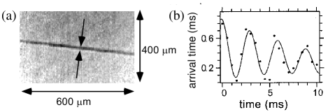
An absorption image of the trapped cesium atoms at K is depicted in Fig. 7(a) showing the rod-shaped cloud of atoms. The distribution of atoms had a radial extension m and a axial size of m corresponding to a peak density of atoms/cm3. The picture was taken 30 ms after the cooling had been turned off. The time interval is large compared to the radial oscillation period ( Hz), but short compared to the axial oscillation period ( Hz). In this transient regime, the axial distribution had not yet reached its thermal equilibrium extension of m which leads to a decrease of the density. For the radial extension, the measured value coincided with the expectation for thermal equilibrium as determined by the measured temperature and oscillation frequency (see Eq. 36).
To measure the transverse oscillation frequency, the Nd:YAG beam was interrupted for a ms time interval, during which the cold atoms were accelerated by gravity to a mean velocity about 1 cm/s. After the trapping laser had been turned on again, the atoms vertically oscillate in the trap. The oscillation in vertial velocity was detected by measuring the mean arrival time of the atoms at a probe laser beam 12 cm below the trap [ordinate in Fig. 7(b)] as a function of the trapping time intervals [abscissa in Fig. 7(b)]. The measured vertical oscillation frequency Hz is consistent with the value Hz derived from the trap depth and the beam waist.
The temperatures measured in the dipole trap were about 30 times lower than one would expect on the basis of the heating rates found for a isotropic free-space sample at the corresponding densities (Boiron et al., 1995). No evidence was found for heating of the trapped sample. The reduction of density-dependent heating is a benefit from the strongly anisotropic trapping geometry of a focused-beam trap. Due to the much smaller volume to surface ratio of an atomic cloud in the focused-beam trap as compared to a spherical distribution, photons emitted during cooling have a higher chance to escape without reabsorption from the trap sample which causes less heating through reabsorption.
4 Bose-Einstein condensates
Optical confinement of Bose-Einstein condensates was demonstrated for the first time by a group at MIT in Cambridge, USA (Stamper-Kurn et al., 1998a). Bose condensates represent the ultimately cold state of an atomic sample and are therefore captured by extremely shallow optical dipole traps. High transfer efficiencies can be reached in very far-detuned traps, and the photon scattering rate acquires negligibly small values (see Eq. 14). Various specific features of dipole traps can fruitfully be applied to the investigation of many aspects of Bose-Einstein condensation which were not accessible formerly in magnetic traps.
Sodium atoms were first evaporatively cooled in a magnetic trap to create Bose condensates containing atoms in the state (Mewes et al., 1996). Subsequently, the atoms were adiabatically transferred into the dipole trap by slowly ramping up the trapping laser power, and then suddenly switching off the magnetic trap. The optical trap was formed by a laser beam at 985 nm (396 nm detuning from resonance) focused to a waist of about m. A laser power of 4 mW created a trap depth of about K which was sufficient to transfer 85% of the Bose condensed atoms into the dipole trap and to provide tight confinement. Peak densities up to atoms/cm3 were reported representing unprecendented high values for optically trapped atomic samples.
Condensates were observed in the dipole trap even without initially having a condensate in the magnetic trap. This strange effect could be explained by an adiabatic increase of the local phase-space density through changes in the potential shape (Pinkse et al., 1997). The slow increase of the trapping laser intensity during loading leads to a deformation of the trapping potential created by the combination of magnetic and laser fields. The trapping volume of the magnetic trap was much larger than the volume of the dipole trap. Therefore, phase-space density was increased during deformation, while entropy remained constant through collisional equilibration. Using the adiabatic deformation of the trapping potential, a 50-fold increase of the phase-space density was observed in a later experiment (Stamper-Kurn et al, 1998b).
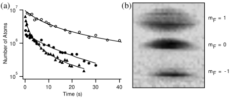
The lifetime of atoms in the dipole trap is shown in Fig. 8(a) in comparison to the results obtained in a magnetic trap. In the case of tight confinement and high densities (triangles in Fig. 8), atoms quickly escape through inelastic intra-trap collisions. Long lifetimes (circles in Fig. 8) were achieved in the dipole trap and the magnetic trap, respectively, when the trap depth was low enough for collisionally heated atoms to escape the trap. Trap loss was found to be dominated by three-body decay with no identifiable contributions from two-body dipolar relaxation. The lifetime measurements delivered the three-body loss rate constant cm6/s (see Eq. 37) for collisions among condensed sodium atoms.
Fig. 8(b) demonstrates simultaneous confinement of a Bose condensate in different Zeeman substates of the ground state. To populate the substates, the atoms were exposed to an rf field sweep (Mewes et al., 1997). The distribution over the Zeeman states was analyzed through Stern-Gerlach separation by pulsing on a magnetic field gradient of a few G/cm after turning off the dipole trap. It was verified that all substates were stored stably for several seconds.
After the first demonstration of optical trapping, a spectacular series of experiments with Bose-Einstein condensates in a dipole trap was performed by the MIT group. By adiabatically changing the phase-space density in the combined magnetic and optical dipole trap (see above), Stamper-Kurn et al. (1998b) were able to reversibly cross the transition to BEC. Using this technique, the temporal formation of Bose-Einstein condensates could extensively be studied (Miesner et al, 1998a). The possibility of freely manipulating the spin of trapped atoms without affecting the trapping potential has led to the observation of Feshbach resonances in ultracold elastic collisions (Inouye et al., 1998) and the investigation of spin domains and metastable states in spinor condensates (Stenger et al., 1998, Miesner et al., 1998b).
5 Quasi-electrostatic traps
The very interesting case of quasi-electrostatic dipole trapping has so far not been considered in this review. When the frequency of the trapping light is much smaller than the resonance frequency of the first excited state , the light field can be regarded as a quasi-static electric field polarizing the atom. Quasi-electrostatic traps (QUEST) were first proposed (Takekoshi et al., 1995) and realized (Takekoshi and Knize, 1996) by a group at University of Southern California in Los Angeles. In the quasi-electrostatic approximation , one can write the dipole potential as
| (41) |
with denoting the static polarizability (). The light-shift potential of the excited states is also attractive contrary to far-off resonant interaction discussed before. Atoms can therefore be trapped in all internal states by the same light field. Since the trap depth in Eq. 41 does not depend on the detuning from a specific resonance line as in the case of a FORT, different atomic species or even molecules may be trapped in the same trapping volume.
For the ground state of alkali atoms, Eq. 41 is well approximated by applying the quasi-static approximation to Eq. 10 which gives
| (42) |
Compared to a FORT at a detuning , the potential depth for ground state atoms in a QUEST is smaller by a factor . Therefore, high power lasers in the far-infrared spectral range have to be employed to create sufficiently deep traps. The CO2 laser at 10.6 m which is commercially available with cw powers up to some kilowatts is particulary well suited for the realization of a QUEST (Takekoshi et al., 1995).
An important feature of the QUEST is the practical absence of photon scattering. The relation between the photon scattering rate and the trap potential can be derived from Eqs. 10 and 11 in the quasi-electrostatic approximation:
| (43) |
When compared to the corresponding relation for a FORT given by Eq. 14, the dramatic decrease of the photon scattering rate in a QUEST becomes obvious. Typical scattering rates are below s-1 showing that the QUEST represents an ideal realization of a purely conservative trap.
Takekoshi and Knize (1996) have realized trapping of cesium atoms in a QUEST by focussing a 20 W CO2 laser to a waist of m resulting in a trap depth of K. Around atoms prepared in the state were loaded into the trap from a standard MOT. The atom loss rates of s were consistent with pure losses through background gas collisions. Hyperfine relaxation times were found to exceed 10 s.
B Standing-wave traps
A standing wave (SW) trap provides extremely tight confinement in axial dimension as can be seen from Fig. 5(b). The trap can be realized by simply retroreflecting the beam while conserving the curvature of the wave fronts and the polarization. Assuming small extensions of the atomic cloud, one can write the potential in the form
| (44) |
with the standing wave oriented along the -axis. The potential depth is four times as large than the corresponding trap depth for a single focused beam discussed in Sec. IV A. As for a single focused beam, radial confinement is provided by a restoring force . The axial trapping potential is spatially modulated with a period of . Atoms are strongly confined in the antinodes of the standing wave (restoring force ) resulting in a regular one-dimensional lattice of pancake-like atomic subensembles. When aligned vertically, the axial confinement greatly exceeds the gravitational force . One can therefore use rather shallow trap, just sufficiently deep to trap a pre-cooled ensemble, which results in small photon scattering rates (see Eq. 14) and large loading efficiencies.
The tight confinement along the axial direction leads to large oscillation frequencies at the centre of the trap. The oscillation frequency decreases when moving along the -axis due to the decreasing light intensity. At low temperatures, the energy of the axial zero-point motion in the centre of the trap can become of the same order of magnitude as the thermal energy even for moderate trap depths *‡*‡*‡Using the recoil temperature for the cooling transition at the wavelength introduced in Sec. III A 1, one can write the zero-point energy as .. In this regime, the axial atomic motion can no longer be described classically but has to be quantized, and the vibrational ground state of the axial motion is substantially populated. The axial spread of the wavepacket is much smaller than the wavelength of an optical transition (Lamb-Dicke regime) giving rise to spectral line-narrowing phenomena. One might even enter a regime where the wavepacket extension comes close to the s-wave scattering length leading to dramatic changes in the collisional properties of the trapped gas.
1 Optical cooling to high phase-space densities
Well-resolved vibrational levels and Lamb-Dicke narrowing, as realized along the axis of a standing-wave dipole trap, are necessary requirements for the application of optical sideband cooling as explained in Sec. III A 1. By employing degenerate-sideband Raman cooling, high phase-space densities of an ensemble containing large particle numbers have been achieved by Vuletic et al. (1998) from a group in Stanford. In a vertical far-detuned standing wave, peak phase- space densities around 1/180 have been obtained with cesium atoms, corresponding to a mean temperature of K and a peak spatial density of atoms/cm3.
The trap was generated by a Nd:YAG laser with 17 W single-mode power at nm. The large beam waist of m created a trap depth of K which resulted in high loading efficiencies ( from a blue-detuned molasses released from a MOT) and small photon scattering rates (). Atoms oscillated at Hz in the radial (horizontal) direction, and at kHz in the axial (vertical) direction. A dramatic dependence of the trap lifetime on the hyperfine state of the cesium atoms was observed similar to Fig. 4 in Sec. III C. Around atoms were contained in the trap populating 4700 vertical potential wells. Degenerate Raman sideband cooling was applied between vibrational states of a pair of Zeeman shifted magnetic sublevels in the lowest hyperfine ground state as explained in Sec. III A 1. Suppressed collisional losses through inelastic binary collisions at high densities are greatly suppressed since population in the upper hyperfine state is kept extremely low in this cooling scheme. The Raman coupling was provided by the lattice field itself (Deutsch and Jessen, 1998).
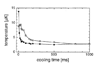
Axial and radial temperatures evolved differently during cooling as indicated in Fig. 9. The axial direction was directly cooled causing the axial temperature to quickly drop to K. The radial temperature followed by collisional thermalization with a time constant of 150 ms. After sideband cooling was turned off, the temperature increased at a rate of K/s limiting the achievable final temperatures. This heating rate was much larger than the rate estimated on the basis of photon scattering which might indicate additional heating sources such as laser noise. The achieved high thermalization rates in combination with large particle numbers would provide excellent starting conditions for subsequent evaporative cooling.
A different approach to optical cooling of large particle numbers to high phase-space densities was followed by a group at Berkeley (Winoto et al., 1998), who have recently applied polarization-gradient cooling to cesium atoms in a vertical standing-wave trap. The standing wave was linearly polarized resulting in equal light shifts for all magnetic sublevels of the atomic ground state (see Sec. II B 2). Therefore, polarization-gradient cooling, which relies on optical pumping between the ground-state sublevels (see Sec. III A 1), could be applied to the trapped sample in a very efficient way. A phase-space density around with the large number of atoms was reached.
2 Quantum interference
The regular arrangement of atoms in a standing wave-dipole trap has amazing consequences when a Bose condensate is loaded into such a trap. Macroscopic interference of Bose condensed 87Rb atoms tunneling from an extremely shallow 1D lattice under the influence of gravity has recently been observed by Anderson and Kasevich (1998) at Yale University. The dipole potential was created by a vertical standing wave at 850 nm (detuning of 65 nm from the line) with a waist of m, an order of magnitude larger than the transverse radius of the condensate. The condensate of atoms was coherently distributed among very shallow potential wells. The wells supported only one bound energy band below the potential edge which is equivalent to where is the recoil temperature (see Eq. 22) at the wavelength of the trapping field.
The gravitational field induces an offset between adjacent wells. For weak potential gradients, the external field can be treated as a perturbation th the band structure associated with the lattice. In this limit, wavepackets remain confined in a single band. The external field drives coherent oscillations at the Bloch frequency as has been demonstrated with ultracold atoms confined in an accelerated far-detuned 1D standing wave by Ben Dahan et al. (1996) at ENS in Paris and by Wilkinson et al. (1996) at University of Texas in Austin.
The shallow potential wells allow for tunneling of particles into unbound continuum states. In the Yale experiment, the lifetime of the atoms confined in the lattice was purely determined by the tunneling losses. For a lattice of depth , the observed lifetime was ms. Each lattice site can be seen as a point emitter of a deBroglie wave. Interference between the different emitter ouputs lead to the formation of atom pulses falling out of the standing wave, quite similar to the output of a mode-locked pulsed laser. The pulse repetition frequency was determined by the gravitational increment between two adjacent walls. The repetition frequency can be interpreted as the difference in chemical potential divided by . This indicates the close relation of the observed effect of coherent atomic deBroglie waves to the ac Josephson effect resulting from quantum interference of two superconducting reservoirs.
3 Spin manipulation
Zielonkowski et al. (1998b) from the MPI für Kernphysik in Heidelberg have used a vertical standing wave trap for the manipulation of spin-polarized atoms. By using a large-volume, shallow red-detuned standing wave trap, depolarizing effects of photon scattering and atomic interactions could be kept at a low level while allowing for large numbers of stored atoms.
Cesium atoms were trapped in a retroreflected 220-mW beam at a wavelength of nm (detuning of 6.1 nm above the line). The waist of the beam in the interaction region was 0.50 mm. The maximum potential depth amounted to only K which was sufficiently deep to directly load atoms from a MOT at sub-Doppler temperatures. Despite the shallow potential depth, the confining force exceeded the gravitational force by about three orders of magnitude. The transfer efficiency from the MOT into the shallow trap was about 14% resulting in trapped atoms at a liftime of s as shown by the stars in Fig. 10(a).
In a first experiment, the spin state was selected by a Stern-Gerlach (SG) force. The force was created by horizontally shifting the zero of the MOT quadrupole field with respect to the position of the dipole trap (see Fig. 10(b)). In this way, only atoms with are trapped by the dipole trap, all other magnetic substates are pulled out of the trap by the magnetic dipole force. The depolarizing effect of the trap light was determined by measuring the lifetime of the atoms (see circles in Fig. 10(a)) and comparing this value with the trap lifetime without Stern-Gerlach selection. The depolarization rate s-1 allowed a determination of the photon scattering rate from calculated values of the -state branching ratios for spontaneous scattering. The resulting scattering rate agrees well with the expectation based on Eq. 21.

In a second experiment, spin precession in a ficitious magnetic field (Cohen-Tannoudji and Dupont-Roc, 1972, Zielonkowski et al., 1998a) was demonstrated. The field was induced by an additional off-resonant circularly polarized laser beam which induced a light shift scaling linear with as discussed in Sec. II B 2. The resulting splitting corresponds to a fictitious magnetic field of 50 mG. The state was selected by a short Stern-Gerlach pulse resulting in a macroscopic magnetization of the sample. The population of the same state was analyzed after a 150 ms delay. Between preparation and analysis, the atoms interacted with a pulse of the fictitious field laser in combination with a holding magnetic field. The population oscillates with the duration of the laser pulses which can be directly interpreted as the Larmor precession of the spin in the superposition of fictitous and holding magnetic field. A and a rotation of the magnetization were observed.
4 Quasi-electrostatic lattices
A standing wave created by the light at m from a CO2 laser creates a QUEST (see Sec. IV A 5) with a spacing between the axial potential wells which is large compared to the transition wavelength of the trapped atoms. In a group at the MPI für Quantenoptik in Garching, such a lattice of mesoscopic potential wells was recently realized with rubidium atoms (Friebel et al., 1998a; 1998b). A 5 W CO2 laser beam was focused to a waist of 50 m creating a trap depth of about K. Up to atoms could be loaded into the horizontal standing wave trap which had a lifetime of s limited by background gas collisions. Temperatures around 10 K were achieved by polarization gradient cooling in the trap.
The vibrational frequencies of atoms inside the potential wells were measured by modulating the laser intensity in order to drive parametric excitation of the atomic oscillations. When the modulation frequency equals twice the vibrational frequency (or subharmonics ), atoms are heated out of the trap leading to a reduced lifetime. This effect was demonstrated by varying the modulation frequency and measuring the number of atoms
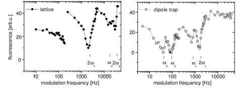
that were left in the trap after a fixed trapping time of 600 ms. The remaining atoms were detected by switching on a resonant light field and recording the fluorescence. The left graph in Fig. 11 shows the excitation spectrum for the standing-wave trap. Parametric resonances at 2 kHz and at 32 kHz can be identified which are attributed to excitations of the radial and axial vibrations, respectively. A subharmonic resonance at 16 kHz is also observed. In the left graph of Fig. 11, the excitation spectrum of a single focused-beam dipole trap is presented. The trap was realized by interrupting the retroreflected laser beam which had formed the standing wave. The radial resonance shifts to 1.6 kHz (subharmonic at 0.8 kHz) because of the four times lower trap depth. The reduction of the axial vibrational frequency is more dramatic since it scales as relative to the standing-wave trap (including the factor 4 in trap depth). The axial resonance is now found at 80 Hz (subharmonic at 40 Hz).
C Crossed-beam traps
A single focused beam creates a highly anisotropic trap with relatively weak confinement along the propagation axis and tight confinement in the perpendicular direction [see Figs. 5(a) and 7(a)]. In a standing-wave trap, the anisotropic atomic distribution of the single beam trap is split into anisotropic subensembles with extremely tight confinement along the axial direction. Crossing two beams with orthogonal polarization and equal waist under an angle of about as indicated in Fig. 5(c) represents an obvious way to create nearly isotropic atomic ensembles with tight confinement in all dimensions. In this case, the dipole potential for small extensions of the atomic cloud can be approximated as
| (45) |
It should be noted that the effective potential depth is only as atoms with larger energy leave the steep trap along one of the beams.
1 Evaporative cooling
Crossed-beam dipole traps provide a good compromise between decent trapping volumes and tight confinement, and are therefore suited for the application of evaporative cooling as explained in Sec. III A 1. Adams et al. (1995) at Stanford used a crossed-beam configuration oriented in the horizontal plane for evaporative cooling of sodium. A single-mode Nd:YAG laser generated two beams of 4 W each, focused to a waist of m and crossing under . The trap depth was close to 1 mK. The polarizations of the two beams were chosen orthogonal which results in a spin-independent trapping potential for the ground states because of the large detuning of the 1064 nm light from the two fine-structure lines of sodium (see Table I).
After transfer from a MOT, evaporative cooling was started with atoms at a temperature of K and a peak density of atoms/cm3 as indicated by the dotted lines in Fig. 12. To force evaporation of high-energetic particles, the Nd:YAG power was exponentially ramped down from 8 W (trap depth K) to 0.4 W (trap depth K) within 2 s . After evaporation, atoms were left in the trap. Temperature was reduced by a factor of 35 to K. Yet, density decreased by about an order of magnitude since the restoring force in the trap is reduced when ramping down the intensity. To keep the density at a high value for efficient evaporation, one would have to further compress the cloud. However, compared to the initial conditions, phase-space density was increased by a factor of 28 in the experiment indicating the potential of evaporative cooling for the enhancement of phase-space density in dipole traps.
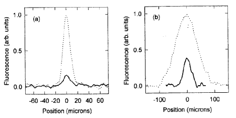
2 Interference effects
Let us now consider the more general case of two beams of equal waist propagating in the -plane and intersecting at the focal points under an arbitrary angle. The angle between the beams and the -axis is . This configuration includes as special cases the single focussed-beam trap (), discussed in Sec. IV A, and the standing wave trap (), discussed Sec. IV B. In the harmonic approximation, the trapping potential can be written as
| (46) |
The potential radii are given by and . The -dependence of the trap depth reflects interference effects between the two waves which lead to a modulation of the trap depth on the scale of an optical wavelength.
If both beams are linearly polarized along the -direction (linlin), interference results in a pure intensity modulation with period yielding . Trapped atoms are therefore bound in the antinodes of the interference pattern forming a one-dimensional lattice along the -direction with lattice constant . In the case of orthogonal polarization of the two beams (linlin), the intensity exhibits no interference effects, but the polarization is spatially modulated between linear and circular with the same period . As discussed in Sec. II B 2, the light shift depends on the spin state of the atoms giving rise to a spatial modulation of the potential. For detunings large compared to the fine-structure splitting , the potential depth is modulated with a relative amplitude (see Eq. 20).
Making use of these interference effects, the ENS group has investigated Raman cooling (Kuhn et al., 1996) and sideband cooling (Perrin et al., 1998; Bouchoule et al., 1998) in a crossed-beam trap for cesium atoms. The trap consisted of two Nd:YAG laser beams (nm) propagating along a vertical -plane with a power of about 5 W in each beam. The beams crossed at their common waists (m) under an angle with the horizontal -axis. The hyperfine splitting of ground and excited state were small compared to the detuning of the laser from the and lines of cesium at 894 nm and 852 nm, respectively. For the linlin case, the comparatively large fine-structure splitting of cesium () lead to spatially modulated potentials with a small, yet significant modulation amplitude of for the stretched Zeeman states .
The trap was loaded from cesium atoms in a MOT. The loading efficiency and the shape of the atomic cloud strongly depended on the laser polarizations of the dipole trap (Kuhn et al., 1996). The potential wells formed by interference of the laser beams were used for resolved-sideband cooling with Raman transitions between the and hyperfine ground states. Great differences in the performance of sideband cooling were found for the linlin and the linlin case due to the different character of the potential wells being weakly or strongly modulated, respectively (Perrin et al. 1998). By optimizing the sideband cooling in the linlin configuration, single vibrational states (motional Fock states) could be prepared in the 1D standing wave. Atoms were first sideband-cooled into the lowest vibrational state from where they could be transferred into other pure states by Raman transitions at multiples of the resolved vibrational sidebands (Bouchoule et al., 1998).
D Lattices
When adding more laser beams, one can design a whole variety of interference patterns to create two- and three-dimensional lattices confining the atoms in micropotentials of submicron extension (Deutsch and Jessen, 1998). When combined with efficient cooling methods, significant population of the vibrational ground state can be achieved. Many important aspects of these optical lattices have extensively been studied for near-resonant trapping fields which simultaneously provide tight confinement and dissipation (Jessen and Deutsch, 1996; Hemmerich et al., 1996; Grynberg and Triche, 1996).
In this chapter, we have so far concentrated on red-detuned traps because of the conceptual differences in the practical realization of dipole traps as compared to blue-detuned traps discussed in the next chapter. In the case of three-dimensional far-detuned lattices, this distinction becomes faint since both lattice types are realized through appropriate interference patterns of multiple beams. The atoms are trapped either in the antinodes (red detuning) or nodes (blue detuning) of the interference pattern. The main difference for red and blue detuning lies in the photon scattering rates as discussed in Sec. III A 3. Here, we shortly present novel developments for both types of far-off resonance lattices recently realized by several groups (Anderson et al., 1996; Müller-Seydlitz et al., 1997; Hamann et al., 1998; Boiron et al., 1998; DePue et al., 1998). Localized wavepackets oscillating in conservative microtraps are promising systems in which to study fundamental questions related to quantum-state preparation, coherent control and decoherence of macroscopic superposition states. Furthermore, optical lattices can serve as prototype systems for the study of condensed matter models based on periodic arrangements of weakly interacting particles.
Anderson et al. (1996) have confined lithium atoms in three-dimensional optical lattices formed in the intersection of four laser beams. For lithium, the fine-structure splitting is only 10 GHz leading to ground-state optical potentials which are independent of the light polarization and the atomic spin state. A face-centered cubic lattice with a nearest-neighbor spacing of was realized by a four-beam configuration. Three-dimensional lattices with periodicity much larger than could be created by reducing the angles subtended by each possible pair of the four lattice beams *§*§*§A different approach to create structures with large periodicities has been used by Boiron et al. (1998) by using interference from multiple beams emerging from a holographic phase grating.. Up to atoms were trapped in the lattice. By reducing the intensity of the trapping light so that only the coldest atoms from a MOT were confined in the lattice, a trapped ensemble with an rms velocity spread corresponding to 1.8 K was prepared. By adiabatically expanding deep potential wells (see Sec. III A 1), cooling at the expense of smaller spatial density could be achieved.
The temporal evolution of metastable argon atoms stored in the intensity nodes of a blue-detuned optical lattice was investigated by Müller-Seydlitz et al. (1997) at Konstanz University. The lattice of simple-cubic symmetry was formed by three mutually orthogonal standing waves with othogonal linear polarizations resulting in isotropic potential wells with a lattice constant of nm. About atoms are initially captured in the lattice. Fig. 13 shows time-of-flight spectra for variable trapping times. After a certain storage time,
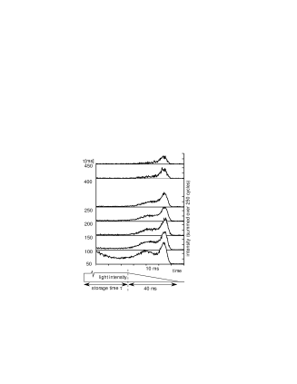
the light intensity is ramped down releasing one bound state after the other. For increasing storage times, the population of excited bands in the potential wells decreases faster than the population of the vibrational ground-state band leaving about 50 atoms populating the motional ground state after storage times of about 450 ms. Two processes could be identified for this state selective loss of particles: Firstly, atoms in higher excited bands have a higher probability of leaving the finite extension of the trapping field (mm) by tunneling. Secondly, atoms interacting with the far-off resonance trapping light (detuning 2 nm from resonance for the metastables) are optically pumped into the electronic ground state of argon and are therefore lost from the trap. The probability for an optical pumping process depends on the spatial overlap between the optical lattice field and the atomic wavepacket confined to the potential well. The smaller the spatial extension of the wavepackets, the smaller is the excitation rate being smallest for the motional ground state. The reduced photon scattering probability of deeper bound states is an important specific property of a blue-detuned optical lattice.
The first demonstration of resolved-sideband Raman cooling in a dipole trap explained in Sec. III A 1 was performed with cesium in a two-dimensional lattice by a group at University of Arizona in Tucson (Hamann et al., 1998). The 2D lattice consisted of three coplanar laser beams with polarizations in the lattice plane. A magnetic field perpendicular to the lattice plane was applied to Zeeman-shift the motional states and of the upper hyperfine ground state into degeneracy (see Sec. III A 1). By adding a small polarization component orthogonal to the lattice plane, Raman coupling between magnetic sublevels with was introduced. In Fig. 14, the inverse Boltzmann factor is plotted versus the magnetic field. The inverse Boltzmann factor reaches a maximum when the two motional states are shifted into degeneracy by the magnetic field, so that sideband cooling by the lattice field becomes effective. The second, smaller peak shows well-resolved cooling on the second-order Raman sideband (). As shown by the inset in Fig. 14, the thermal energy of the atoms closely approaches the zero-point energy in the potential wells indicating a population of the vibrational ground state.
Unity occupation of sites in a three-dimensional far-off resonance optical lattice was very recently realized by the Berkeley group (DePue et al., 1998). In the regime of unity occupation, interactions between highly localized atoms have dramatic effects, and studies of collisional properties of tightly bound wavepackets become possible. The necessary high densities were achieved by applying polarization gradient cooling to the 3D lattice filled with cesium atoms, and subsequent adiabatic toggling between the 3D lattice and a 1D standing wave. The 3D lattice was formed by three mutual orthogonal standing waves with controlled time-phase differences. After the atoms were cooled in the lattice, the horizontal beams of the lattice are adiabatically turned off leaving the atoms in a vertical standing wave trap. Due to their low temperature (700 nK), the atoms were essentially at rest at their respecive positions. Under the action of the transverse trapping potential, the atoms radially collapsed towards the trap centre. All atoms arrived simultaneously at the centre after about a quarter radial oscillation period. Thereby, the density in the trap centre was transiently enhanced by a factor of ten reaching atoms/cm3. At the moment of peak density, the horizontal lattice beams were adiabatically turned on again. A substantial fraction of lattice sites was then multiply occupied and underwent fast inelastic collisions. After multiply occupied sites had decayed, 44% of the lattice site were occupied by a single atom cooled close near its vibrational ground state.
V Blue-detuned dipole traps
Laser light acts repulsively on the atoms when its frequency is higher than the transition frequency (“blue” detuning). The basic idea of a blue-detuned dipole trap is thus to surround a spatial region with repulsive laser light. Such a trap offers the great advantage of atom storage in a “dark” place with low influence of the trapping light, which minimizes unwanted effects like photon scattering, light shifts of the atomic levels, and light-assisted collisional losses. According to the discussion following Eq. 33, this advantage becomes substantial in the case of hard repulsive optical walls ( in Eq. 33) or large potential depth for tight confinement ().
Experimentally, it is not quite as simple and straightforward to realize a blue-detuned trap as it is in the red-detuned case, where already a single tightly focused laser beam constitutes an interesting dipole trap. Therefore, the development of appropriate methods to produce the required repulsive “optical walls” has played a central role in experiments with blue-detuned traps. Three main methods have been applied for this purpose: Light sheets, produced by strong elliptical focusing of a laser beam, can be used as nearly flat optical walls (Davidson et al., 1995; Lee et al., 1996). Hollow laser beams can provide spatial confinement in at least two dimensions (Yang et al., 1986). Evanescent waves, formed by total internal reflection on the surface of a dielectric medium, represent nearly ideal mirrors to reflect atoms (Cook and Hill, 1982; Dowling and Gea-Banacloche, 1996). In most blue-detuned traps, gravity is used to close the confining potential from above. Such traps are referred to as gravito-optical traps. As a further experimental possibility, which we have already discussed in Sec. IV D, atoms can be trapped in the micropotentials of far blue-detuned optical lattices (Müller-Seydlitz et al., 1997).
In this Chapter, we discuss various blue-detuned traps that have been realized experimentally and their particular features; an overview is given in Table II. In the following, these traps are classified according to the main method applied for producing the optical walls: Light-sheet traps (Sec. V A), hollow-beam traps (Sec. V B), and evanescent-wave traps (Sec. V C).
A Light-sheet traps
In experiments performed at Stanford University, Davidson et al. (1995) and Lee et al. (1996, 1998) have realized light-sheet traps of various configurations and applied them for rf spectroscopy on trapped atoms and for optical cooling to high phase-space densities. The light sheets were derived from the two strongest lines of an all-line argon-ion laser. A laser power of up to 10 W at 514 nm and up to 6 W at 488 nm was focused with cylindrical lenses to cross sections of typically 15 m 1 mm. For the Na atoms used in the experiments (resonance line at 589 nm), this leads to maximum light-sheet potentials in the order of 100 K.
When two light sheets are combined and overlap in space, there are two ways to avoid perturbing interference effects, which could open escape channels in the optical potential. First, if the two light sheets have different frequencies then the relevant potential is determined by the time average over the rapid beat node, in which the interference averages out. Second, if the light sheets have same frequencies but orthogonal polarizations then interference leads to a spatial modulation of the polarization. In the case of large detunings greatly exceeding the fine-structure splitting, as it was very well fulfilled in the Stanford experiments, the polarization modulation has negligible effect on the dipole potential (see Eq. 20).
In the first experiment (Davidson et al., 1995), two horizontally propagating light sheets were combined to form a vertical “V” cross section. This configuration already provides 3D confinement, as the trapping potential is closed along the propagation direction due to the divergence of the tightly focused light, see Fig. 15(a). Vertically, the atoms are kept in the trap by gravity. The gravito-optical trap thus has the form of a boat with a length of about 2 mm (for trap parameters see Table II).
Using this light-sheet trap, Davidson et al. have stored about 3000 Na atoms and impressively demonstrated the advantages of blue-detuned dipole traps for spectroscopic applications. By using the method of separated oscillatory fields, they have measured Ramsey fringes of the hyperfine transition of the Na ground state. For the excitation of this transition an rf travelling wave with a frequency of 1.77 GHz was used. The Ramsey fringes were measured by applying two rf pulses separated by a time delay of up to 4 s. Initially, all trapped atoms were optically pumped into the lower hyperfine state . After applying of the two rf pulses, the number of atoms transfered into the upper state was measured by applying a short pulse of light resonant with the cycling transition and detecting the induced fluorescence. The two central Ramsey fringes observed by varying the rf frequency for a pulse delay of 4 s are shown in Fig. 15(b). By analyzing the dependence of the fringe contrast on the delay between the two rf pulses, a coherence decay time of s was obtained.
In the same experiments, the Stanford group has also measured the mean residual light shift (ac Stark shift) of the hyperfine transition frequency as caused by the trapping light. From the frequency of the central Ramsey fringe, a corresponding shift of 270 mHz was observed. The absolute light shifts of the two hyperfine sublevels are larger by the ratio of the optical detuning ( 90 THz) to the hyperfine splitting (1.77 GHz) and thus amounted to 14 kHz. This number directly gives the average dipole potential kHzK experienced by the atom and also allows one to determine an average photon scattering rate of 0.01 s-1 according to equation 14.
The authors also mention similar experiments performed in a red-detuned dipole trap realized with a Nd:YAG laser. In this case, the longest observed coherence times were 300 times lower, which highlights the advantage of the blue-detuned geometry for in-trap spectroscopy.
In a later experiment (Lee et al., 1995), the light-sheet trapping was improved by a new trap geometry in the form of an inverted pyramid. As illustrated in Fig. 16(a), this trap was produced by four sheets of light. Due to the much larger trapping volume provided by the pyramidal geometry this trap could be loaded with atoms, which constitutes an improvement over the previous configuration by more than a factor of 100 (see also Table II). Lee et al. have also tested a similar, tetrahedral box trap, the performance of which was inferior to the inverted pyramid.
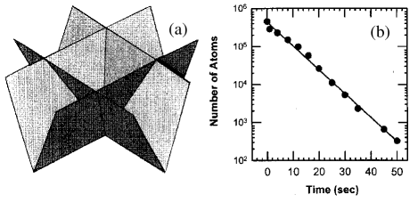
The particular motivation of the experiment by Lee et al. was to obtain high phase-space densities of the trapped atomic ensemble by optical cooling. The authors therefore applied 1D Raman cooling (Kasevich and Chu, 1992) as a sub-recoil cooling method, see also Sec. III A 1. The geometry of the inverted-pyramid trap is very advantageous for getting dense atomic samples, because of a strong spatial compression with decreasing temperature. In an ideal inverted pyramid the density would scale as in contrast to a 3D harmonic oscillator, where . Moreover, this trap configuration provides very fast motional coupling between the different degrees of freedom, which is particularly interesting in case of a 1D cooling scheme.
About atoms were loaded at a temperature of 7.7 K and a peak density of cm-3. By applying a sequence of Raman cooling pulses during the following 180 ms, the temperature of the atoms was reduced to 1 K and, keeping practically all atoms in the trap, a peak density of 4 cm-3 was reached. This density increase by a factor of 20 resulting from a temperature reduction by a factor of about 7 indicates that the trap was already in a regime where the confining potential behaves rather harmonically than like in an ideal pyramid. This may be explained by the finite transverse decay length of the light-sheets potential walls. As a result of the Raman cooling, the atomic phase-space density was increased by a factor of 320 over the initial one and reached a value which was about a factor of from Bose-Einstein condensation.
After an initial loss of atoms observed in the first second after the Raman cooling process, an exponential decay of the trapped atom number was measured with a time constant of 7 s, see Fig. 16(b). This loss did not significantly depend on the background pressure below mbar, which points to the presence of an additional single-particle loss mechanism. This loss was consistent with an observed heating process in the trap that 30 times exceeded the calculated heating by photon scattering. This heating of unknown origin was identified as the main obstacle to implement evaporative cooling in the inverted pyramid trap. The experiments moreover showed evidence that ground-state hyperfine-changing collisions, ejecting atoms out of the trap, were limiting the maximum density achievable with Raman cooling to 1012 cm-3.
In a later experiment, Lee and Chu (1998) used the inverted-pyramid trap for preparing a Raman-cooled sample with spin polarization in any of the three magnetic sub-levels of the lower hyperfine ground state (). A small bias magnetic field was used to lift the degeneracy of the ground state and appropriate polarization was chosen for the Raman cooling light. The attained temperature and phase-space density was similar to the unpolarized case. This experiment can be seen as a nice illustration of the general advantage of dipole trapping to leave the full ground-state manifold available for experiments.
B Hollow-beam traps
Hollow blue-detuned laser beams, which provide radial confinement, are particularly interesting and versatile tools for the construction of dipole traps. Hollow laser beams may be divided into two classes: Beams in pure higher-order Laguerre-Gaussian (LG) modes and other hollow beams which cannot be represented as single eigenmodes of an optical resonator. The main difference is that LG beams preserve their transverse profile with propagation (only converging or diverging in width), which is of particular interest for atom guiding (Dholakia, 1998; Schiffer et al., 1998). Other, non-LG hollow beams can change their profile substantially, thus offering additional features of interest for atom trapping.
A Laguerre-Gaussian mode LG is characterized by a radial index and an azimuthal index . A hollow beam with a “doughnut” profile is obtained for and with an intensity distribution given by
| (47) |
here is the power and is the waist of the beam. For this equation gives the transverse profile of a usual Gaussian beam (TEM00 mode) as described by Eq. 38. The higher the mode index , the larger is the ratio between the beam radius and the width of the ring, i.e. the harder is the repulsive optical wall radially confining the atoms and the weaker is heating by photon scattering.
1 Plugged doughnut-beam trap
The dougnut-beam trap shown in Fig. 17(a) was recently realized by Kuga et al. (1997) at the University of Tokyo; see also Table II. The LG03 doughnut beam (=0.6 mm) was derived from a laser which was forced to oscillate in a Hermite-Gaussian HG03 mode by insertion of a thin wire into the cavity. An astigmatic mode convertor (Beijersbergen et al., 1993) then transformed the beam into the LG03 mode. As a LG beam does not provide axial confinement, the hollow beam was plugged by two additional laser beams (diameter 0.7 mm), which were separated by 2 mm and perpendicularly intersected the hollow beam. The plugging beams were derived from the recycled doughnut beam.
An exponential decay of the stored atom number was observed with a time constant of about 150 ms [see Fig. 17(b)], which was explained by heating out of the trap by photon scattering. The authors also observed that trapping in a LG01 mode showed inferior performance with very short lifetimes of a few milliseconds only, which highlights the benefit of “hard” optical walls for reducing heating by photon scattering.
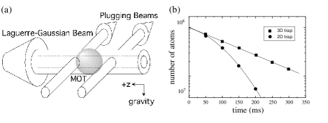
In subsequent experiments (Torii et al., 1998), the storage time of the trap was improved by application of a pulsed optical molasses cooling scheme to a value of 1.5 s, which then was dominated by collisions with the background gas. This non-continuous molasses cooling scheme allows one to cool the atoms down to nearly the same temperatures as in a continuous cooling scheme, but suppresses trap losses by light-assisted collisions and the interference of light shifts from the molasses light with the trapping potential. Moreover, potentially severe losses by hyperfine-changing collisions (see Sec. III C) can be strongly reduced by keeping the atoms in the lower hyperfine ground states in the off-times of the molasses. In such a pulsed cooling scheme, the off-time can be as long as heating by photon scattering (see Sec. III A 2) does not significantly degrade the trap performance. The on-time can be as short as the typical cooling time in the molasses.
2 Single-beam traps
A blue-detuned trap based on a single laser beam was recently demonstrated by Ozeri et al. (1998) at the Weizman Institute in Israel; see also Table II. The trapping beam was produced in an experimentally very simple way by passing a single Gaussian beam through a phase plate of appropriate size, which shifted the center of the beam by a phase angle of . In the focus of such a beam, destructive interference leads to a reduced or even vanishing light intensity. By choosing the proper ratio between the diameter of the phase plate and the laser beam diameter, Ozeri et al. obtained a darkness ratio (central intensity normalized to maximum intensity) of 1/750. Close to the center of this single-beam trap, the intensity increases radially with the fourth power of the distance (like in the case of a LG02 beam) and axially the dependence is quadratic.
In order to measure the average light intensity experienced by the atoms in the trap, Ozeri et al. have studied the relaxation of hyperfine population caused by photon scattering from the trapping light in a similar way as done by Cline et al. (1994) in a red-detuned far-off-resonance trap; see also Sec. IV A 2. From measurements performed at a detuning of 0.5 nm it was concluded that the average intensity experienced by a trapped atom was as low as 1/700 of the maximum intensity. In another series of measurements they observed that, at constant temperature, the photon scattering rate scaled linearly with the inverse detuning. This observed behavior represents a nice confirmation of Eq. 29, which for a power-law potential directly relates the average scattering rate to the temperature with an inverse proportionality to the detuning.
In a recent proposal, Zemanek and Foot (1998) considered a blue-detuned dipole trap formed by two counterpropagating laser beams of equal central intensities, but different diameters. Along the axis of such a standing-wave configuration, completely destructive interference would lead to minima of the dipole potential with zero intensity. These traps would be radially closed because of the incomplete destructive interference at off-axis positions. This resulting linear array of three-dimensional dipole traps could combine the interesting features of standing-wave trapping schemes (see Sec. IV B) with the advantages of blue detuning. Experimentally, it seems straightforward to realize such a trap by retroreflection and appropriate attenuation of a single slightly converging laser beam.
3 Conical atom trap
A single-beam gravito-optical trap was recently demonstrated by Ovchinnikov et al. (1998) at the MPI für Kernphysik in Heidelberg. The “conical atom trap” (CAT), illustrated in Fig. 18(a), is based on a conical hollow beam and combines experimental simplicity with several features of interest for the trapping of a large number of atoms at high densities: high loading efficiency, tight confinement, low collisional losses, and efficient cooling.
In the experiment (parameters see Table II) the upward directed conical trapping beam was generated by using an arrangement of two axicons and one spherical lens. In the focal plane, the beam profile was roughly Gaussian with a diameter of about 100 m. Within a few millimeters distance from the focus, the beam evolved into a ring-shaped profile with a dark central region resembling a higher-order Laguerre-Gaussian mode. The opening angle of the conical beam was about 150 mrad.
The trap was operated relatively close to resonance as compared to the other blue-detuned traps discussed so far. With an optical detuning of 3 GHz (12 GHz) with respect to the lower (upper) hyperfine ground state of Cs a large potential depth was realized, which together with the funnel-like geometry facilitated the transfer of as much as 80% of all atoms from the MOT into the CAT. The relatively small detuning requires efficient cooling for removing the heat resulting from photon scattering from the trapping light. For this purpose, an optical molasses was applied continuously to cool atoms in the upper hyperfine ground state. This cooling, however, takes place with an inherently reduced duty cycle and is thus similar to the pulsed molasses cooling scheme of Torii et al. (1998), which was discussed before. In the molasses scheme applied in the CAT, the short phases of cooling in the upper hyperfine ground state (typically 50 s) are self-terminating by optical pumping into the lower hyperfine level. There the atoms stay for a much longer time (typically 1 ms) until they are repumped by the light of the intense conical trapping beam.
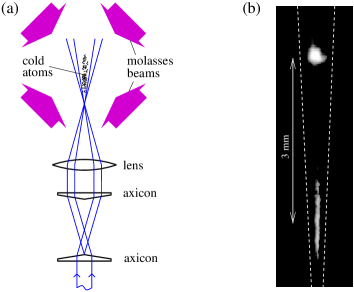
This inherent duty cycle for the molasses provides cooling phases which are long enough to efficiently remove heat, while the average population of the upper hyperfine state is kept very low. This efficiently suppresses trap loss due to hyperfine-changing collisions (see Sec. III C). At an atomic number density of cm-3 lifetime measurements of the trapped atoms ( lifetime of 7.8 s due to background gas collisions) showed no significant loss due to ultracold collisions, which indirectly confirmed the predominant population of the lower hyperfine ground state.
The CAT was also operated in a pure “reflection cooling” mode without any molasses cooling, similar to the situation that was theoretially considered by Morsch and Meacher (1998). Reflection cooling (Ovchinnikov et al., 1995a and b) is based on the inelastic reflection of an atom from a blue-detuned light field, as discussed in more detail in the following section in context with evanescent waves. In a Sisyphus-like process the atom is pumped from the strongly repulsive lower to the weakly repulsive upper hyperfine state. A closed cooling cycle requires a weak repumping beam to bring the atom back to the lower state. Such a beam was applied in the CAT experiment from above. The detuning of the conical beam was increased to a few ten GHz to optimize reflection cooling. Because of the lower potential depth the loading was less efficient (10% transfer from the MOT instead of 80% reached before), but stable background-gas limited trapping was achieved. Without the repumping beam, atoms were rapidly heated out of the trap. These observations clearly demonstrated reflection cooling in a blue-detuned trap made of free-propagating light fields. However, optimum reflection cooling requires very steep optical walls so that only evanescent waves are suited to reach temperatures close to the recoil limit by this mechanism, as will be discussed in Sec. V C 3.
C Evanescent-wave traps
A hard repulsive optical wall with nearly ideal properties can be realized by a blue-detuned evanescent wave (EW), produced by total internal reflection of a laser beam from a dielectric-vacuum interface. In the vacuum the EW intensity falls off exponentially within a typical distance of from the surface and thus provides a very large gradient. The use of an EW as a mirror for neutral atoms was suggested by Cook and Hill (1982), who also proposed to trap atoms in a box realized with EW mirrors. The first experimental demonstration of an atom mirror was made by Balykin et al. (1987) by grazing-incidence reflection of a thermal atomic beam. A few years later, Kasevich et al. (1990) observed reflection of cold atoms at normal incidence. Since then many experiments have been conducted with EW atom mirrors. An extensive review on EW atom mirrors and related trapping schemes has already been given by Dowling and Gea-Banacloche (1996). We thus concentrate on the essential issues and some interesting, new developments.
1 Evanescent-wave atom mirror
The exponential shape of the repulsive optical potential of a far-detuned EW leads to simple expressions for the basic properties of such an atom mirror. The EW intensity as a function of the distance from the surface is given by
| (48) |
where the decay length depends on the angle of incidence and the refractive index of the dielectric. The maximum EW intensity is related to the incident light intensity by .
The repulsive dipole potential of an atom mirror is independent of the magnetic substate if the detuning is large compared to the excited-state hyperfine splitting and the EW is linearly polarized (see Sec. 2); the latter is obtained for an incoming linear polarization perpendicular to the plane of incidence (TE polarization). In the interesting case of low saturation, the EW dipole potential can then be calculated according to Eq. 19.
A very important quantity to characterize the EW reflection process is its probability to take place coherently, i.e. without spontaneous photon scattering. The probability for an (in)coherent reflection can be calculated by integrating the intensity-dependent scattering rate (Eq. 21) over the classical trajectory of the atom in the repulsive potential. For large enough laser detuning (still close to one of the lines), the resulting small probability for an incoherent reflection process is given by
| (49) |
where is the velocity component perpendicular to the surface.
The light shift of the ground-state sublevel integrated over time in a single reflection process corresponds to a phase shift
| (50) |
experienced by the atom. The simple relation is a result of the fundamental connection between the absorptive and dispersive effect of the interaction with the light field (see also Eq 14). As an interesting consequence of the exponential shape of the EW potential, both equations Eq. 49 and Eq. 50 do not depend on the intensity of the light field, as long as the potential barrier is high enough. For higher/lower intensities the reflection just takes place at larger/smaller distances from the surface.
Very close to the surface (nm), the van-der-Waals attraction becomes significant. Its main effect is to reduce the maximum potential barrier provided by the EW mirror (Landragin et al., 1996b). For small kinetic energies, the reflected atoms do not penetrate deeply into the EW and thus do not feel the surface attraction. We have thus neglected the effect of the van-der-Waals force in Eqs. 49 and 50, and we will do so in the following.
2 Gravito-optical cavities
A great deal of interest in EW atom mirrors has been stimulated by the intriguing prospect to build resonators and cavities for atomic de-Broglie waves (Balykin and Letokhov, 1989; Wallis et al., 1992). The simplest way to realize such a scheme is a single atom mirror on which the atoms classically bounce like on a trampoline. Such a trapping scheme is referred to as gravito-optical cavity.
The time between two bounces in a gravito-optical cavity is related to the maximum height and the maximum velocity of the atoms by , where is the gravitational acceleration. Using Eq. 49 for the probability for photon scattering per bounce, the average photon scattering rate can be expressed as
| (51) |
Analogously using Eq. 50, the mean light shift experienced by the bouncing atom is obtained as
| (52) |
It is a remarkable consequence of the exponential shape of the EW potential that and do not depend on the energy of the atom. For an atom with less energy in a gravito-optical cavity, the decrease in scattering probability and light shift is exactly compensated by the higher bounce rate.
The average scattering rate can be interpreted as the decoherence rate of gravito-optical resonator due to photon scattering. It also determines the heating power according to Eq. 23. The mean light shift is of interest for possible spectroscopic applications of gravito-optical cavities.
The eigenenergies of the vertical modes in a gravito-optical cavity can be approximately calculated by idealizing the EW potential as a hard wall (Wallis et al., 1992). In this case the vertical potential has the shape of a wedge and the energy of the -th vertical mode is given by
| (53) |
where is a characteristic frequency. For example, for cesium atoms =2080 Hz, which corresponds to a temperature of nK. Consequently, the population of a single vertical mode with many atoms, a challenging issue for future experiments, requires cooling below this temperature.
As an important step for EW trapping, the ENS group in Paris observed the bouncing of atoms in a stable gravito-optical cavity (Aminoff et al., 1993). The atom mirror used in the experiment (diameter 1.5 mm) was produced on a concave spherical substrate (radius of curvature 2 cm) to obtain additional transverse confinement of the atomic motion (Wallis et al., 1992); the resulting transverse trap depth was about 5 K.
In the set-up sketched in Fig.19(a), about cold atoms were dropped onto the mirror from a MOT located at a height of 3 mm above the prism (corresponding bounce period ms). The bouncing atoms were detected by measuring the fluorescence in a resonant probe beam, which was applied to the atoms after a variable time delay. The experimental results displayed in Fig. 19(b) show up to ten resolved bounces, after which the number of atoms dropped below the detection limit. The measured loss per bounce of 40% was attributed to photon scattering during the EW reflection process ( 5% according to Eq. 49), photon scattering from stray light from the mirror ( 10%), collisions with the background gas ( 10%), and another, not identified source of loss ( 20%). An explanation for the latter may be the diffusive reflection from an EW mirror, as observed later by Landragin et al. (1996a). The ENS gravito-optical cavity represents the first atom trap realized with evanescent waves.
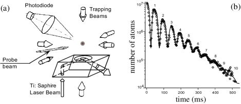
3 Gravito-optical surface trap
A new step for gravito-optical EW traps was the introduction of a dissipative mechanism, following suggestions by Ovchinnikov et al. (1995a) and Söding et al. (1995) to cool atoms by inelastic reflections. In a corresponding experiment at the MPI für Kernphysik in Heidelberg, Ovchinnikov et al. (1997) have realized the gravito-optical surface trap (GOST) schematically shown in Fig. 20(a); see also Table II. This trap facilitates storage and efficient cooling of a dense atomic gas closely above an EW atom mirror.
A flat atom mirror was used in the GOST and horizontal confinement was achieved by a hollow, cylindrical laser beam, far blue-detuned from the atomic resonance. This beam with a ring-shaped transverse intensity profile providing very steep optical walls was generated using an axicon (Manek et al., 1998). A Laguerre-Gaussian beam of similar performance would require extremly high order (about LG0, 100). The optical potentials of the GOST thus come very close to ideal hard walls, which leads to a strong reduction of photon scattering from the trapping light even relatively close to resonance.
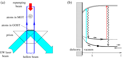
Cooling by inelastic EW reflections (evanescent-wave Sisyphus cooling) is the key to stable trapping in the GOST. The basic mechanism, which was experimentally studied before in grazing-incidence reflection of an atomic beam (Ovchinnikov et al. 1995b; Laryushin et al., 1996) and normal-incidence reflection of cold atoms (Desbiolles et al., 1996), is based on the splitting of the 2S1/2 ground state of an alkali atom into two hyperfine sublevels. In the case of linear EW polarization, the atom can be modeled as a three-level scheme (Söding et al., 1995; see also Sec. II B 2) with two ground states separated by and one excited state, for which the hyperfine splitting can be neglected.
An inelastic reflection takes place when the atom enters the EW in the lower ground state and, by scattering an EW photon during the reflection process, is pumped into the less repulsive upper state; see Fig. 20(b). The cooling cycle is then closed by pumping the atom back into the lower hyperfine state with a weak resonant repumping laser (coming from above in Fig. 20(a)). The mean energy loss from the motion perpendicular to the surface per inelastic reflection is given by , where is the kinetic energy of the incoming atom and is the relevant detuning with respect to the lower hyperfine state. With the probability for an incoherent reflection according to Eq. 49, the branching ratio for spontaneous scattering into the upper ground state, and the bounce rate EW Sisyphus cooling can be characterized by a simple cooling rate
| (54) |
The vertical motion is damped exponentially because the average photon scattering rate is independent of the kinetic energy (see Eq. 51). The final attainable temperature is recoil-limited to a value of , similar to a polarization-gradient optical molasses (see Sec. III A 1).
The GOST was experimentally realized for Cs atoms, the high mass of which is very favorable for gravito-optical trapping: In the gravitational potential, the recoil temperature corresponds to a height , which for the heavy Cs atoms is particularly low (m, see also Table I). As a consequence, Cs atoms cooled close to the recoil limit can be accumulated very close to the dielectric surface.
In the experiment, trapped atoms were observed for storage times up to 25 s, corresponding to more than 10.000 (unresolved) bounces. The observed exponential loss with a -lifetime of 6 s was completely consistent with collisions with the background gas. By time-of-flight diagnostics, a temperature of 3.0 K was measured, which is quite close to the theoretical cooling limit. In thermal equilibrium, the number density as function of the distance from the surface follows from Eq. 34 (in this case, equivalent to the barometric equation), which for the measured temperature of 3.0 K corresponds to an exponential decay with a height as low as 19 m.

The cooling dynamics observed in the experiments is shown in Fig. 21. The initial horizontal temperature is determined by the temperature of the MOT, whereas the much higher initial vertical temperature results from the release of the atoms at a height of 800m. With increasing storage time, the vertical temperature follows a nearly exponential decay with a time constant of ms, in good agreement with the cooling rate according to Eq. 54 (with = 1 GHz, = 9.2 GHz, ). The temperature of the horizontal motion, which is not cooled directly, follows the vertical one with a clearly visible time lag and approaches the same final value of about 3 K. This apparent motional coupling can be fully explained by a small diffusive component of the reflection from the EW atom mirror, as observed before by Landragin et al. (1996a).
A very important feature of the GOST and the evanescent-wave cooling mechanism is the predominant population of the absolute internal atomic ground state: The lower hyperfine level is populated by more than 99.99% of the atoms. A unique feature of EW cooling is that the trapping and cooling light does not penetrate the atomic sample. Moreover, a possible reabsorption of scattered trap photons is strongly reduced because of the large surface area for photons to escape. Due to these facts trap loss by ultracold collisions (see Sec. III C) and other density-limiting mechanisms are strongly suppressed as compared to a MOT. One can therefore expect EW Sisyphus cooling to work very well up to number densities of 1013 cm-3, or even higher (Söding et al., 1995). In the first GOST experiments, this interesting regime was out of reach because the trap could be loaded with only atoms, leading to peak densities of cm-3. In present experiments with the GOST, being performed with a substantially improved loading scheme, the high-density regime of evanescent-wave cooling is being explored.
The GOST offers several interesting options for future experiments on dense atomic gases (Engler et al., 1998). By detuning the EW and the hollow beam very far from resonance, a situation can be reached in which the photon scattering rate is far below 1 s-1. For a sufficiently dense gas, one can then expect very good starting conditions for evaporative cooling, which may be implemented by ramping down the EW potential. This appears to be a promising route to quantum-degeneracy of Cs, which because of anomalously fast dipolar relaxation seems not attainable in a magnetic trap (Söding et al., 1998; Guéry-Odelin et al., 1998).
Other interesting applications of the GOST, arising from its particular geometry, are related to the possible formation of a two-dimensional quantum gas. The vertical motion is much more strongly confined than the horizontal one, so that the corresponding level spacings of the quantized atomic motion differ by nearly six orders of magnitude. In such a highly anisotropic situation, Bose-Einstein condensation is predicted to occur in two distinct steps (van Druten and Ketterle, 1997). First, the vertical motion condenses into its ground state (Wallis, 1996). Then, in a second step occuring at much lower temperatures, the system condenses to its absolute ground state. The highly anisotropic nature of the trapping potential may be further enhanced by addition of a second, attractive evanescent-wave (Ovchinnikov et al., 1991). This can create a wavelength-sized potential well close to the surface, which could be efficiently loaded by elastic collisions. The situation would then resemble the situation of atomic hydrogen trapped on liquid helium, for which evidence of a Kosterlitz-Thouless phase transition was reported very recently (Safonov et al., 1998). The prospect to realize such a system with alkali atoms*¶*¶*¶Other experimental approaches to two-dimensional systems based on dipole trapping make use of the particular properties of the optical transition structure in metastable noble gas atoms (Schneble et al., 1998; Gauck et al., 1998). is of particular interest to study effects of quantum-degeneracy in a 2D system.
VI Concluding remarks
In this review, we have discussed the basic physics of dipole trapping in far-detuned light, the typical experimental techniques and procedures, and the different presently available trap types along with their specific features. In the discussed experiments, optical dipole traps have already shown their great potential for a variety of different applications.
The particular advantages of dipole trapping can be summarized in the following three main points:
-
The ground-state trapping potential can be designed to be either independent of the particular sub-level, or dependent in a well-defined way. In the first case, the internal ground-state dynamics under the influence of additional fields behaves in the same way as in the case of a free atom.
-
Photon scattering from the trap light can take place on an extremely long time scale exceeding many seconds. The trap then comes close to the ideal case of a conservative, non-dissipative trapping potential, allowing for long coherence times of the internal and external dynamics of the stored atoms.
-
Light fields allow one to realize a great variety of different trap geometries, e.g., highly anisotropic traps, multi-well potentials, mesoscopic and microscopic traps, and potentials for low-dimensional systems.
Regarding these features, the main research lines for future experiments in optical dipole trapping may be seen in the following fields:
Ultracold collisions and quantum gases.
The behavior of ultracold, potentially quantum-degenerate atomic gases is governed by their specific collisional properties, which strongly depend on the particular species, the internal states of the colliding atoms, and possible external fields. In this respect, dipole traps offer unique possibilities as they allow to store atoms in any sub-state or combination of sub-states for the study of collisional properties and collective behavior. Experiments along these lines have already been performed (Gardner et al., 1995; Tsai et al., 1997; Stenger et al., 1998; Miesner et al., 1998b), but it seems that this has just opened the door to many other studies involving other atomic species, or even mixtures of different species (Engler et al., 1998).
Of particular importance is the trapping of atoms in the absolute internal ground state, which cannot be trapped magnetically. In this state, inelastic binary collision are completely suppressed for energetical reasons. In this respect, an ultracold cesium gas represents a particularly interesting situation, as Bose-Einstein condensation seems only attainable for the absolute ground state (Söding et al., 1998; Guéry-Odelin et al., 1998). As a consequence, an optical trap may be the only way to realize a quantum-degenerate gas of Cs atoms.
Tuning of scattering properties by external fields is another very interesting subject. In this respect, Feshbach resonances at particular values of magnetic fields play a very important role. In optical traps one is completely free to choose any magnetic field without changing the trap itself. Using this advantage, Feshbach resonances have been observed for sodium and rubidium (Inouye et al., 1998; Courteille et al., 1998), and future experimental work will certainly explore corresponding collisional properties of other atomic species.
Highly anisotropic dipole traps offer a unique environment for the realization of low-dimensional quantum gases. In this respect, interesting trapping configurations are standing-wave traps (Sec. IV B), optical lattices (Sec. IV D), evanescent-wave surface traps (Sec. V C), and combinations of such trapping fields (Gauck et al., 1998). New phenomena could be related to a step-wise Bose-Einstein condensation (van Druten and Ketterle, 1997) and modifications of scattering properties in cases, in which the atomic motion is restricted to a spatial scale on the order of the -wave scattering length.
Another fascinating issue would be to study collisional properties of ultracold fermions (e.g., the alkali atoms 6Li and 40K) with the challenging goal to produce a quantum-degenerate Fermi gas. Direct optical cooling in a standing-wave dipole trap by degenerate sideband cooling, similar to the method of Vuletic et al. (1998), seems to be a particularly promising route.
Spin physics and magnetic resonance.
As dipole traps allow for confinement with negligible effect on the atomic ground-state spin, experiments related to the coherent ground-state dynamics in external fields can be performed in essentially the same way as in the case of free atoms. In such experiments, the trap would provide much longer observation times as attainable in atomic beams or vapor cells. As a further advantage, trapped atoms stay at the same place which keeps inhomogeneties of external fields very low. First demonstrations of along this line are the experiments by Davidson et al. (1995) and Zielonkowski et al. (1998b), as discussed in Sec. V A and IV B 3, respectively. In principle, a dipole trap constitutes an appropriate environment to perform any kind of magnetic resonance experiment with optically and magnetically manipulated ground-state spins (Suter, 1997). This could be of interest, e.g., for storing and processing quantum information in the spin degrees of freedom.
A possible, very fundamental application would be the measurement of a permanent electric dipole moment of a heavy paramagnetic atom like cesium (Khriplovich and Lamoreaux, 1997). Such an experiment, testing time-reversal symmetry, could greatly benefit from extremely long spin lifetimes and coherence times of spin polarization, which seem to be attainable in dipole traps.
Trapping of other atomic species and molecules.
Optical dipole traps do neither rely on a resonant interaction with laser light nor on spontaneous photon scattering. Therefore any polarizable particle can be trapped in powerful, sufficiently far-detuned light. For this purpose, the quasi-electrostatic trapping with far-infrared laser sources, like CO2 lasers (see Secs. IV A 5 and IV B 4), appears to be very attractive. The trapping mechanism could be applied to many other atomic species or molecules, which are not accessible to direct laser cooling. The problem is not the trapping itself, but the cooling to the very low temperatures required for trap loading. There may be several ways to overcome this problem.
A possible way to load a dipole trap could be based on buffer-gas loading of atoms or molecules into magnetic traps (Kim et al., 1997; Weinstein et al., 1998) and subsequent evaporative cooling. The effectiveness of cryogenic loading and subsequent evaporative cooling is demonstrated by the recent attainment of Bose-Einstein condensation of atomic hydrogen confined in a magnetic trap (Fried et al., 1998), without any optical cooling involved. Similar strategies based on buffer-gas loading could open ways for filling optical dipole traps with many more atomic species than presently available or even with molecules.
Another possible way could be the production of ultracold molecules by photoassociation of laser-cooled atoms (Fioretti et al., 1998). The translational energies of these molecules can be low enough for loading into far-infrared dipole traps. A very recent experiment by Takekoshi et al. (1998) indeed reports evidence of dipole trapping of a few Cs2 molecules in a CO2-laser beam, which may just be the beginning of a new class of experiments in dipole trapping.
Optical dipole traps can be seen as storage devices at the low end of the presently explorable energy scale. We are convinced that future experiments exploiting the particular advantages of these traps will reveal interesting new phenomena and show many surprises.
Acknowledgments
We would like to thank Hans Engler, Markus Hammes, Moritz Nill, Ulf Moslener, M. Zielonkowski, and in particular Inka Manek from the Heidelberg cooling and trapping group for many useful discussions and assistance in preparing the manuscript. Further useful discussions are acknowledged with Steven Chu, Lev Khaykovich, Takahiro Kuga, Heun Jin Lee, Roee Ozeri, Christophe Salomon, and Vladan Vuletic. We are grateful to Dirk Schwalm for supporting the work on laser cooling and trapping at the MPI für Kernphysik. One of us (Yu.B.O.) acknowledges a fellowship by the Alexander von Humboldt-Stiftung. Our work on dipole trapping is generously supported by the Deutsche Forschungsgemeinschaft in the frame of the Gerhard-Hess-Programm.
References
Adams, C.S., Sigel, M., and Mlynek, J. (1994). Phys. Rep. 240, 143.
Adams, C.S., Lee, H.J., Davidson, N., Kasevich, M., and Chu, S. (1995). Phys. Rev. Lett. 74, 3577.
Adams, C.S., and Riis, E. (1997). Prog. Quant. Electron. 21, 1.
Allen, L., and Eberly, J.H. (1975). Optical resonance and two-level atoms (Wiley, New York).
Aminoff, C.G., Steane, A., Bouyer, P., Desbiolles, P., Dalibard, J., and Cohen-Tannoudji, C. (1993). Phys. Rev. Lett. 71, 3083.
Anderson, B.P., Gustavson, T.I., and Kasevich, M.A. (1996). Phys. Rev. A 53, R3727.
Anderson, M.H., Ensher, J.R., Matthews, M.R., Wieman, C.E., and Cornell, E. (1995). Science 269, 198.
Anderson, B.P., and Kasevich, M.A. (1998). Science, in press.
Andrews, M.R., Mewes, M.-O., van Druten, N.J., Durfee, D.S., Kurn, D.M., and Ketterle, W. (1996). Science 273, 84.
Andrews, M.R., Kurn, D.M., Miesner, H.-J., Durfee, D.S., Townsend, C.G., Inouye, S., and Ketterle, W. (1997). Phys. Rev. Lett. 79, 553.
Arimondo, E., Phillips, W.D., and Strumia, F., eds. (1992). Laser Manipulation of Atoms and Ions Proceedings of the International School of Physics “Enrico Fermi”, Varenna, 9 - 19 July 1991, (North Holland, Amsterdam).
Ashkin, A (1970). Phys. Rev. Lett. 24, 156.
Ashkin, A. (1978). Phys. Rev. Lett. 40, 729.
Askar’yan, G.A. (1962). Sov. Phys. JETP 15, 1088.
Aspect, A., Arimondo, E., Kaiser, R., Vansteenkiste, N., and Cohen-Tannoudji, C. (1988). Phys. Rev. Lett. 61, 826.
Balykin, V.I., and Letokhov, V.S. (1989). Appl. Phys. B 48, 517.
Balykin, V.I., Letokhov, V.S., Ovchinnikov, Yu.B., and Sidorov, A.I. (1987). JETP Lett. 45, 353; Phys. Rev. Lett. 60, 2137 (1988).
Beijersbergen, M.W., Allen, L., van der Veen, H.E.L.O., and Woerdman, J.P., Opt. Commun. 96, 123 (1993).
Ben Dahan, M., Peik, E., Reichel, J., Castin, Y., and Salomon, C. (1996). Phys. Rev. Lett. 76, 4508.
Bergeman, T., Erez, G., and Metcalf, H.J. (1987). Phys. Rev. A 35, 1535.
Bergström, I., Carlberg, C., and Schuch, R., eds. (1995). Trapped charged particles and fundamental applications (World Scientific, Singapore); also published as Physica Scripta T59.
Bjorkholm, J.E., Freeman, R.R., Ashkin, A., and Pearson, D.B. (1978). Phys. Rev. Lett. 41, 1361.
Boesten, H.M.J.M., Tsai, C.C., Verhaar, B.J., and Heinzen, D.J. (1997). Phys. Rev. Lett. 77, 5194.
Boiron, D., Triché, C., Meacher, D.R., Verkerk, P., and Grynberg, G. (1995). Phys. Rev. A 52, R3425.
Boiron, D., Michaud, A., Lemonde, P., Castin, Y., Salomon, C., Weyers, S., Szymaniec, K., Cognet, L., and Clairon, A. (1996). Phys. Rev. A 53, R3734.
Boiron, D., Michaud, A., Fournier, J.M., Simard, L., Sprenger, M., Grynberg, G., and Salomon, C. (1998). Phys. Rev. A 57, R4106.
Bouchoule, I., Perrin, H., Kuhn, A., Morinaga, M., and Salomon, C. (1998). Phys. Rev. A, in press.
Bradley, C.C., Sackett, C.A., Tollet, J.J., and Hulet, R.G. (1995). Phys. Rev. Lett. 75, 1687.
Bradley, C.C., Sackett, C.A., and Hulet, R.G. (1997). Phys. Rev. Lett. 78, 985.
Chen, J., Story, J.G., Tollett, J.J., and Hulet, R.G. (1992). Phys. Rev. Lett. 69, 1344.
Cho, D. (1997). J. Kor. Phys. Soc. 30, 373.
Chu, S., Bjorkholm, J.E., Ashkin, A., and Cable, A. (1986). Phys. Rev. Lett. 57, 314.
Chu, S. (1998). Rev. Mod. Phys. 70, 686.
Cline, R.A., Miller, J.D., Matthews, M.R., and Heinzen, D.J. (1994a). Opt. Lett. 19, 207.
Cline, R.A., Miller, J.D., and Heinzen, D.J. (1994b). Phys. Rev. Lett. 73, 632.
Cohen-Tannoudji, C., and Dupont-Roc, J. (1972). Phys. Rev. A 5, 968.
Cohen-Tannoudji, C., Dupont-Roc, J., and Grynberg, G. (1992). Atom-Photon Interactions: Basic Processes and Applications (Wiley, New York).
Cohen-Tannoudji, C. (1998). Rev. Mod. Phys. 70, 707.
Cook, R.J. (1979). Phys. Rev. A 20, 224; ibid. 22, 1078 (1980).
Cook, R.J., and Hill, R.K. (1982). Opt. Commun. 43, 258.
Corwin, K.L., Lu, Z.-T., Claussen, N., , Wieman, C., and Cho, D. (1997). Bull. Am. Phys. Soc. 42, 1057.
Courteille, P., Freeland, R.S., Heinzen, D.J., van Abeelen, F.A., and Verhaar, B.J. (1998). Phys. Rev. Lett. 81, 69.
Dalibard, J., and Cohen-Tannoudji, C. (1985). J. Opt. Soc. Am. B 2, 1707.
Dalibard, J., and Cohen-Tannoudji, C. (1989). J. Opt. Soc. Am. B 6, 2023.
Davidson, N., Lee, H.J., Kasevich, M., and Chu, S. (1994). Phys. Rev. Lett. 72, 3158.
Davidson, N., Lee, H.J., Adams, C.S., Kasevich, M., and Chu, S. (1995). Phys. Rev. Lett. 74, 1311.
Davis, K.B., Mewes, M.-O., Andrews, M.R., van Druten, N.J., Durfee, D.S, Kurn, D.M, and Ketterle, W. (1995). Phys. Rev. Lett. 75, 3969.
DePu, M.T., McCormick, C., Winoto, S.L., Oliver, S., and Weiss, D.S. (1998). “Unity Occupation of Sites in a 3D Optical Lattice”, preprint.
Desbiolles, P., Arndt, M., Szriftgiser, P., and Dalibard, J. (1996a). Phys. Rev. A 54, 4292.
Deutsch, I.H., and Jessen, P. (1997). Phys. Rev. A 57, 1972.
Dholakia, K (1998). Contemp. Phys. 39, 351.
Dieckmann, K., Spreeuw, R.J.C., Weidemüller, M., and Walraven, J. (1998). Phys. Rev. A 58, 3891.
Dowling, J.P., and Gea-Banacloche, J. (1996). Adv. At. Mol. Opt. Phys. 37, 1.
Drewsen, M., Laurent, P., Nadir, A., Santarelli, G., Clairon, A., Castin, Y., Grison, D., and Salomon, C. (1994). Appl. Phys. B 59, 283.
Engler, H., Manek, I., Moslener, U., Nill, M., Ovchinnikov, Yu.B., Schlöder, U., Schünemann, U., Zielonkowski, M., Weidemüller, M., and Grimm, R. (1998). Appl. Phys. B 67, 709.
Fioretti, A., Comparat, D., Crubellier, A., Dulieu, O., Masnou-Seewes, F., and Pillet, P. (1998). Phys. Rev. Lett. 81, 4402.
Foot, C.J. (1991). Comtemp. Phys. 32 369.
Friebel, S., D’Andrea, C., Walz, J., Weitz, M., and Hänsch, T.W. (1998a). Phys. Rev. A 57, R20.
Friebel, S., Scheunemann, R.,, Walz, J., Hänsch,T.W., and Weitz, M. (1998b). Appl. Phys. B 67, 699.
Fried, D.G., Killian, T.C., Willmann, L., Landhuis, D., Moss, S.C., Kleppner, D., Greytak, T.J. (1998). Phys. Rev. Lett. 81, 3811.
Gallagher, A., and Pritchard, D.E. (1989). Phys. Rev. Lett. 63, 957.
Gardner, J.R., Cline, R.A., Miller, J.D., Heinzen, D.J., Boesten, H.M.J.M., and Verhaar, B.J. (1995). Phys. Rev. Lett. 74, 3764.
Gauck, H., Hartl, M., Schneble, D., Schnitzler, H., Pfau, T., and Mlynek, J. (1998). Phys. Rev. Lett. 81, 5298.
Ghosh, P.K. (1995). Ion Traps (Clarendon Press, Oxford).
Gordon, J.P., Ashkin, A. (1980). Phys. Rev. A 21, 1606.
Guéry-Odelin, D., Söding, J., Desbiolles, P., and Dalibard, J. (1998a). Opt. Express 2, 323.
Grynberg, G., and Triché, C., (1996), in Coherent and Collective Interactions of Particles and Radiation Beams, Proceedings of the International School of Physics “Enrico Fermi”, Varenna, 11 - 21 July 1995, edited by Aspect, A., Barletta, W. and Bonifacio, R. (IOS Press, Amsterdam), p. 95.
Guéry-Odelin, D., Söding, J., Desbiolles, P., and Dalibard, J. (1998b). Europhys. Lett., submitted.
Hamann, S.E., Haycock, D.L., Klose, G., Pax, P.H., Deutsch, I.H., and Jessen, P.S. (1998). Phys. Rev. Lett. 80, 4149.
Haubrich, D., Schadwinkel, H., Strauch, F., Ueberholz, B., Wynands, R., and Meschede, D. (1996). Europhys. Lett. 34, 663.
Hemmerich, A., Weidemüller, M., Esslinger, T., Zimmermann, C., and Hänsch, T.W. (1995). Phys. Rev. Lett. 75, 37.
Hemmerich, A., Weidemüller, M., and Hänsch, T.W. (1996), in Coherent and Collective Interactions of Particles and Radiation Beams, Proceedings of the International School of Physics “Enrico Fermi”, Varenna, 11 - 21 July 1995, edited by Aspect, A., Barletta, W. and Bonifacio, R. (IOS Press, Amsterdam), p. 503.
Henkel, C., Molmer, K., Kaiser, R., Vansteenkiste, N., Westbrook, C.I., and Aspect, A., Phys. Rev. A 55, 1160 (1997).
Hess, H.F., Kochanski, G.P., Doyle, J.M., Masuhara, N., Kleppner, D., and Greytak, T.J. (1987). Phys. Rev. Lett. 59, 672.
Inouye, S., Andrews, M.R., Stenger, J., Miesner, H.-J., Stamper-Kurn, D.M., and Ketterle, W. (1998). Nature 392, 151.
Jackson, J.D. (1962). Classical electrodynamics (Wiley, New York).
Jessen, P.S., and Deutsch, I.H. (1996). Adv. At. Mol. Opt. Phys. 37, 95.
Kasevich, M.A., Weiss, D.S., and Chu, S. (1990). Opt. Lett. 15, 607.
Kasevich, M., and Chu, S. (1991). Phys. Rev. Lett. 67, 181.
Kasevich, M.A., and Chu, S., (1992). Phys. Rev. Lett. 69, 1741.
Kastberg, A., Phillips, W.D., Rolston, S.L., Spreeuw, R.J.C., and Jessen, P.S. (1995). Phys. Rev. Lett. 74, 1542.
Kazantsev, A.P. (1973). Sov. Phys. JETP 36, 861; ibid. 39, 784 (1974).
Ketterle, W., and van Druten, N.J. (1996). Adv. At. Mol. Opt. Phys. 37, 181.
Khripolovich, I.B., and Lamoreaux, S.K. (1997). CP Violation Without Strangeness: Electric Dipole Moments of Particles, Atoms, and Molecules (Springer, Berlin).
Kim, J., Friedrich, B., Katz, D.P., Patterson, D., Weinstein, J.D., DeCarvalho, R., and Doyle, J.M. (1997). Phys. Rev. Lett. 78, 3665.
Kuga, T., Torii, Y., Shiokawa, N., and Hirano, T. (1997). Phys. Rev. Lett. 78, 4713.
Kuhn, A., Perrin, H., Hänsel, W., and Salomon, C. (1996). OSA Trends in Optics and Photonics 7, 58.
Landragin, A., Labeyrie, G., Henkel, C., Kaiser, R., Vansteenkiste, N., Westbrook, C.I., and Aspect, A. (1996a). Opt. Lett. 21, 1591.
Landragin, A., Courtois, J.-Y., Labeyrie, G., Vansteenkiste, N., Westbrook, C.I., and Aspect, A. (1996b). Phys. Rev. Lett. 77, 1464.
Laryushin, D.V., Ovchinnikov, Yu.B., Balykin, V.I., and Letokhov, V.S. (1997). Opt. Commun. 135, 138.
Lee, H.J., Adams, C., Davidson, N., Young, B., Weitz, M., Kasevich, M., and Chu, S. (1994). In Atomic Physics 14 edt. by Wineland, D.J., Wieman, C.E., and Smith, S.J. (AIP, New York).
Lee, H.J., Adams, C.S., Kasevich, M., and Chu, S. (1996). Phys. Rev. Lett. 76, 2658.
Lee, H.J., and Chu, S. (1998). Phys. Rev. A 57, 2905.
Lemonde, P., Morice, O., Peik, E., Reichel, J., Perrin, H., Hänsel, W, and Salomon, C. (1995). Europhys. Lett. 32, 555.
Letokhov, V.S. (1968). JETP Lett. 7, 272.
Lett, P.D., Watts, R.N., Westbrook, C.I., Phillips, W.D., Gould, P.L., and Metcalf, H.J. (1988). Phys. Rev. Lett. 61, 169.
Lett, P.D., Phillips, W.D., Rolston, S.L., Tanner, C.E., Watts, R.N., and Westbrook, C. (1989). J. Opt. Soc. Am. B 6, 2084 (1989).
Lett, P.D., Julienne, P.S., and Phillips, W.D. (1995). Annu. Rev. Phys. Chem. 46, 423.
Lu, Z.T., Corwin, K.L., Renn, M.J., Anderson, M.H., Cornell, E.A., and Wieman, C.E. (1996). Phys. Rev. Lett.77, 3331.
Manek, I., Ovchinnikov, Yu.B., and Grimm, R. (1998). Opt. Commun. 147, 67.
Metcalf, H., and van der Straten, P. (1994). Phys. Rep. 244, 203.
Mewes, M.-O., Andrews, M.R., van Druten, N.J., Kurn, D.M., Durfee, D.S., and Ketterle, W. (1996). Phys. Rev. Lett. 77, 416.
Mewes, M.-O., Andrews, M.R., Kurn, D.M., Durfee, D.S., Townsend, and Ketterle, W. (1997). Phys. Rev. Lett. 78, 582.
Miesner, H.-J., Stamper-Kurn, D.M., Andrews, M.R., Durfee, D.S., Inouye, S., and Ketterle, W. (1998a). Science 279, 1005.
Miesner, H.-J., Stamper-Kurn, D.M., Stenger, J., Inouye, S., Chikkatur, A.P., and Ketterle, W. (1998b). Preprint cond-mat/9811161.
Migdall, A.L, Prodan, J.V., Phillips, W.D., Bergemann, T.H., and Metcalf, H.J. (1985). Phys. Rev. Lett. 54, 2596.
Miller, J.D., Cline, R.A., and Heinzen, D.J. (1993a). Phys. Rev. A 47, R4567.
Miller, J.D., Cline, R.A., and Heinzen, D.J. (1993b). Phys. Rev. Lett. 71, 2204.
Minogin, V.G., and Letokhov, V.S. (1987). Laser light pressure on atoms (Gordon and Breach, New York).
Monroe, C., Swann, W., Robinson, H., and Wieman, C. (1990). Phys. Rev. Lett. 65, 1571
Morsch O., and Meacher, D.R., Opt. Commun. 148, 49 (1998).
Müller-Seydlitz, T., Hartl, M., Brezger, B., Hänsel, H., Keller, C., Schnetz, A., Spreeuw, R.J.C., Pfau, T., and Mlynek, J. (1997). Phys. Rev. Lett.78, 1038.
Myatt, C.J., Burt, E.A., ghrist, R.W., Cornell, E.A., and Wieman, C.E. (1997). Phys. Rev. Lett.78, 586.
Ovchinnikov, Yu.B., Shul’ga, S.V., and Balykin, V.I. (1991). J. Phys. B: At. Mol. Opt. Phys. 24, 3173.
Ovchinnikov, Yu.B., Söding, J., and Grimm, R. (1995a). JETP Lett. 61, 21.
Ovchinnikov, Yu.B., Laryushin, D.V., Balykin, V.I., and Letokhov, V.S. (1995b). JETP Lett. 62, 113.
Ovchinnikov, Yu.B., Manek, I., and Grimm, R. (1997). Phys. Rev. Lett. 79, 2225.
Ozeri, R., Khaykovich, L., and Davidson, N. (1998). “Long spin relaxation times in a single-beam blue-detuned optical trap”, preprint.
Perrin, H., Kuhn, A., Bouchoule, I., and Salomon, C. (1998). Europhys. Lett. 42, 395.
Petrich, W., Anderson, M.H., Ensher, J.R., and Cornell, E.A. (1994). J. Opt. Soc. Am. B 11, 1332.
Phillips, W., and Metcalf, H. (1982). Phys. Rev. Lett. 48, 596.
Phillips, W.D. (1998). Rev. Mod. Phys. 70, 721.
Pinkse, P.W.H., Mosk, A., Weidemüller, M., Reynolds, M.W., Hijmans, T.W., and Walraven, J.T.M., Phys. Rev. Lett. 78, 990 (1997).
Pritchard, D.E., Raab, E.L., Bagnato, V.S., Wieman, C.E., and Watts, R.N. (1986). Phys. Rev. Lett. 57, 310.
Raab, E.L., Prentiss, M., Cable, A., Chu, S., and Pritchard, D. (1987). Phys. Rev. Lett. 59, 2631.
Reichel, J., Bardou, F., Ben Dahan, M., Peik, E., Rand, S., Salomon, C., and Cohen-Tannoudji, C. (1995). Phys. Rev. Lett. 75, 4575.
Safonov, A.I., Vasilyev, S.A., Yashnikov, I.S., Lukashevich, I.I., and Jaakola, S. (1998). Phys. Rev. Lett. 81, 4545.
Salomon, C., Dalibard, J., Phillips, W.D., and Guellatti, S. (1990). Europhys. Lett. 12, 683.
Savard, T.A., O‘Hara, K.M., and Thomas, J.E. (1997). Phys. Rev. A 56, R1095.
Schiffer, M., Rauner, M., Kuppens, S., Zinner, M., Sengstock, K., and Ertmer, W. (1998). Appl. Phys. B 67, 705 (1998).
Schneble, D., Gauck, H., Hartl, M., Pfau, T., and Mlynek, J. (1998). in Bose-Einstein condensation of atomic gases, Proceedings of the International School of Physics “Enrico Fermi”, Varenna, 7 - 17 July 1998, edited by Inguscio, M., Stringari, S., and Wieman, C., in press.
Schünemann, U., Engler, H., Zielonkowski, M., Weidemüller, M., and Grimm, R. (1998). Opt. Commun., in press.
Sengstock, K., and Ertmer, W., (1995). Adv. At. Mol. Opt. Phys. 35, 1.
Sesko, D., Walker, T., Monroe, C., Gallagher, A., and Wieman, C. (1989). Phys. Rev. Lett. 63, 961.
Sobelman, I.I. (1979). Atomic Spectra and Radiative Transitions (Springer, Berlin).
Söding, J., Grimm, R., and Ovchinnikov, Yu.B. (1995). Opt. Commun. 119, 652.
Söding, J., Guéry-Odelin, D., Desbiolles, P., Ferrari, G., and Dalibard, J. (1998). Phys. Rev. Lett. 80, 1869.
Stamper-Kurn, D.M., Andrews, M.R., Chikkatur, A.P., Inouye, S., Miesner, H.-J., Stenger, J., and Ketterle, W. (1998a). Phys. Rev. Lett. 80, 2027.
Stamper-Kurn, D.M., Miesner, H.-J., Chikkatur, A.P., Inouye, S. Stenger, J., and Ketterle, W. (1998b). Phys. Rev. Lett. 81, 2194.
Steane, A.M., and Foot, C.J. (1991). Europhys. Lett. 14, 231.
Stenger, J., Inouye, S., Stamper-Kurn, D.M., Miesner, H.-J., Chikkatur, A.P., and Ketterle, W. (1998). Nature, in press.
Stenholm, S. (1986). Rev. Mod. Phys. 58, 699.
Suter, D. (1997). The Physics of Laser-Atom Interactions (University Press, Cambridge).
Takekoshi, T., Yeh, J.R., and Knize, R.J. (1995). Opt. Comm. 114, 421.
Takekoshi, T., and Knize, R.J. (1996). Opt. Lett. 21, 77.
Takekoshi, T., Patterson, B.M., and Knize, R.J. (1998). Phys. Rev. Lett. 81, 5105.
Torii, Y., Shiokawa, N., Hirano, T., Kuga, T., Shimizu, Y., and Sasada, H., Eur. Phys. J. D 1, 239 (1998).
Townsend, C.G., Edwards, N.H., Cooper, C.J., Zetie, K.P., Foot, C.J., Steane, A.M., Szriftgiser, P., Perrin, H., and Dalibard, J. (1995). Phys. Rev. A 52, 1423.
Tsai, C.C., Freeland, R.S., Vogels, J.M., Boesten, H.M.J.M., Verhaar, B.J., and Heinzen, D.J. (1997). Phys. Rev. Lett. 79, 1245.
van Druten, N.J., and Ketterle, W., Phys. Rev. Lett. 79, 549 (1997).
Vuletic, V., Chin, C., Kerman, A.J., and Chu, S., (1998). Phys. Rev. Lett., in press.
Walker, T. and Feng, P. (1994). Adv. At. Mol. Opt. Phys. 34, 125.
Wallace, C.D., Dinneen, T.P., Tan, K.-Y.N., Grove, T.T., and Gould, P.L. (1992). Phys. Rev. Lett. 69, 897.
Wallis, H., Dalibard, J., and Cohen-Tannoudji, C. (1992). Appl. Phys. B 54, 407.
Wallis, H. (1996). Quantum Semiclass. Opt. 8, 727 (1996).
Walther, H. (1993). Adv. At. Mol. Opt. Phys. 31, 137.
Weiner, J. (1995). Adv. At. Mol. Opt. Phys. 35, 45.
Weinstein, J.D., deCarvalho, R., Guillet, T., Friedrich, B., and Doyle, J.M. (1998). Nature 395, 148.
Wilkinson, S.R., Bharucha, C.F., Madison, K.W., Niu, Q., and Raizen, M.G. (1996). Phys. Rev. Lett. 76, 4512.
Winoto, S.L., DePu, M.T., Bramall, N.E., and Weiss, D.S. (1998). “Laser Cooling Large Numbers of Atoms at High Densities”, preprint.
Wineland, D.J., Bergquist, J.C., Bollinger, J.J., and Itano, W.M. (1995). in Trapped charged particles and fundamental applications edt. by Bergström, I., Carlberg, C., and Schuch, R. (World Scientific, Singapore); also published as Physica Scripta T59, 286.
Zemanek, P., and Foot, C.J. (1998). Opt. Commun. 146, 119.
Zielonkowski, M., Steiger, J., Schünemann, U., DeKieviet, M., and Grimm, R. (1998a). Phys. Rev. A 58, in press.
Zielonkowski, M., Manek, I., Moslener, U., Rosenbusch, P., and Grimm, R. (1998b). Europhys. Lett. 44, 700.
![[Uncaptioned image]](/html/physics/9902072/assets/x22.png)
![[Uncaptioned image]](/html/physics/9902072/assets/x23.png)