Imaging Hybrid Photon Detectors with
Minimized Dead Area
and
Protection Against Positive Ion Feedbackaaa
Submitted to Nucl. Inst. Meth. A
Daniel Ferenc
Div. PPE,
CERN,
1211-Geneva,
Switzerland
E-mail: Daniel.Ferenc@CERN.ch
Abstract
Imaging Hybrid Photon Detectors (HPD) have been developed for integration in large area Cherenkov detectors for high energy physics and astrophysics. The presented designs – developed particularly for the experiments MAGIC, LHCb and AQUA-RICH – comprise very good imaging properties, protection against positive ion feedback and(or) minimum dead area. The underlying innovations are discussed in some detail.
1 Introduction
With the onset of new technologies, Hybrid Photon Detectors (HPDs) became one of the most favorable options for the detection of Cherenkov photons in large area Ring Imaging CHerenkov (RICH) detectors. In contrast to ordinary Photo Multiplier Tubes (PMT), where a photoelectron initiates a multi-step amplification process in a dynode system, in HPDs [1] a photoelectron undergoes a single-step acceleration from the photocathode towards the silicon sensor. Due to its relatively high energy (5-20 keV) a photoelectron releases a large number of electron-hole pairs upon its impact in the semiconductor sensor. The number of secondary electrons released in a silicon sensor is N(U-UV, where U0 is the voltage (in Volts) to accelerate an electron to an energy sufficient to penetrate the inert layer above the sensitive semiconductor pn structure.
This publication reports on the solution of two important problems – the minimization of dead area and the protection against positive ion feedback – as implemented in concrete HPD designs. These solutions are, however, very general and may be implemented (with appropriate scaling) in a variety of different designs.
First, we will demonstrate how to minimize the dead area of a large multi-channel imaging HPD in order to enable efficient integration of individual HPD tubes into a large area imaging Cherenkov detector. The method we apply provides undistorted image projection from the entire photocathode to the surface of the pixelized semiconductor sensor. The presented HPD design has been developed [2, 3] for the LHCb experiment. Excellent imaging properties provided in this way are equally welcome in stand-alone devices, like in the 20-inch HPD tube designed for the AQUA-RICH neutrino experiment at Gran Sasso [4] – the second design presented in this publication.
Second, in order to solve the positive ion feedback problem, i.e. to prevent positive ions (released in impacts of photoelectrons from the surface of the semiconductor sensor) from hitting the photocathode, we followed the same idea originally developed for ion feedback protection in small single-channel HPDs [5]. In particular, we shall demonstrate that the insertion of a permanent potential barrier for positive ions in front of the anode may solve the ion feedback problem also in large multi-channel imaging HPDs, but only if the so called cross-focusing electron optics is applied. The ion feedback protection has been developed for the cosmic gamma ray Atmospheric Cherenkov Telescopes (ACT), in particular for the MAGIC project [6].
For all the electron optics simulations presented, SIMION 3D software [7] has been used. In all the figures presented, only elements important for electron optics (focusing electrodes) are shown, while the supporting structures are left out. It is assumed that the medium in the tubes is vacuum.
2 Minimizing the dead area
One of the most important problems in the integration of HPD tubes into a matrix of a large-surface area RICH detector is the low overall photo-sensitive surface coverage, caused by a typically high HPD dead area. HPDs have usually been designed as stand-alone devices, and very little care has been taken of the relationship between the physical and the sensitive surface areas. In those applications where a pixel size of 1-2 cm is sufficient, one can use a matrix consisting of single-pixel HPDs. The large dead area between the sensitive surfaces of the individual detectors may be taken care of by focusing the light to the sensitive photocathode areas by Winston cones or lenses [8]. For applications which require yet a smaller pixel size (e.g. 1 mm), this method is impossible due to the limited possible size of individual tubes, and therefore one should use large diameter HPDs with internal electron optics imaging and multi-channel silicon sensors.
The problem in the integration of these large area imaging HPDs into hexagonal matrices is that it is essentially impossible to use Winston cones to redirect light from the dead area into the sensitive detector area, because that would destroy the image pattern. Demagnification lenses are still possible, but they would have to be very large.
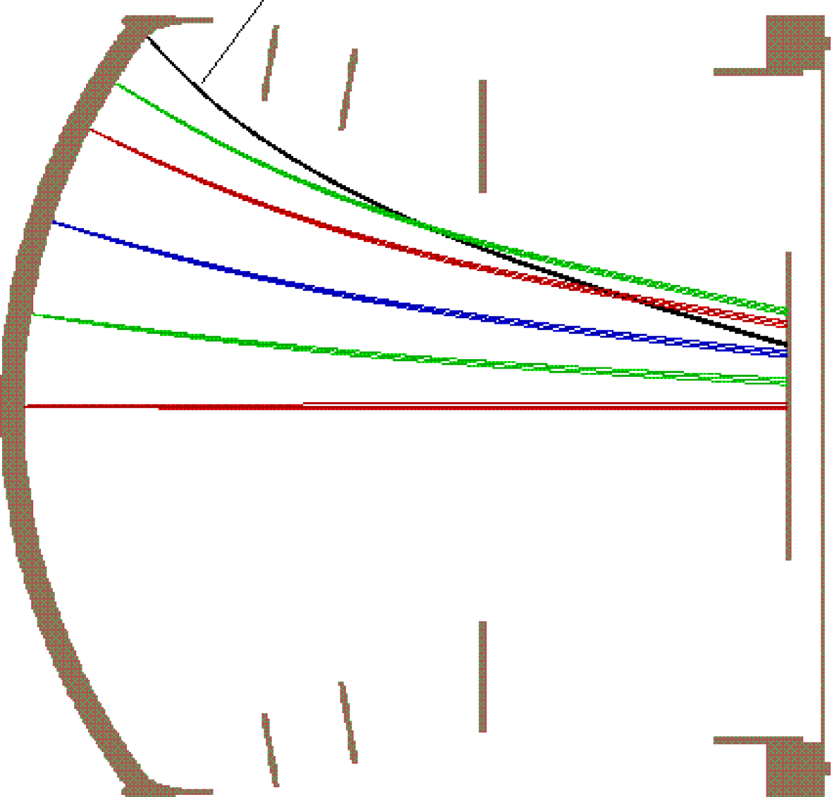
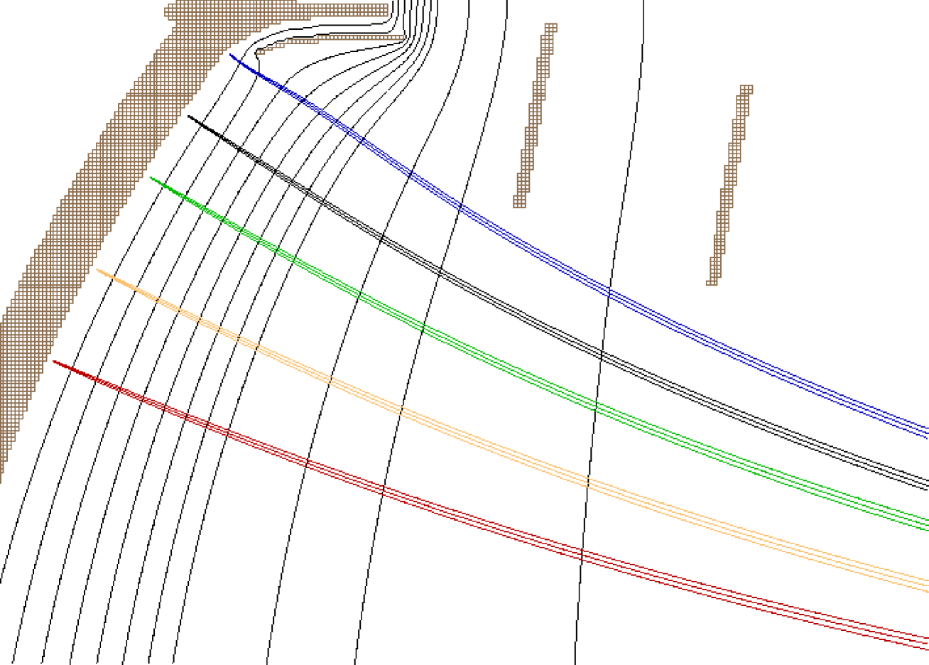
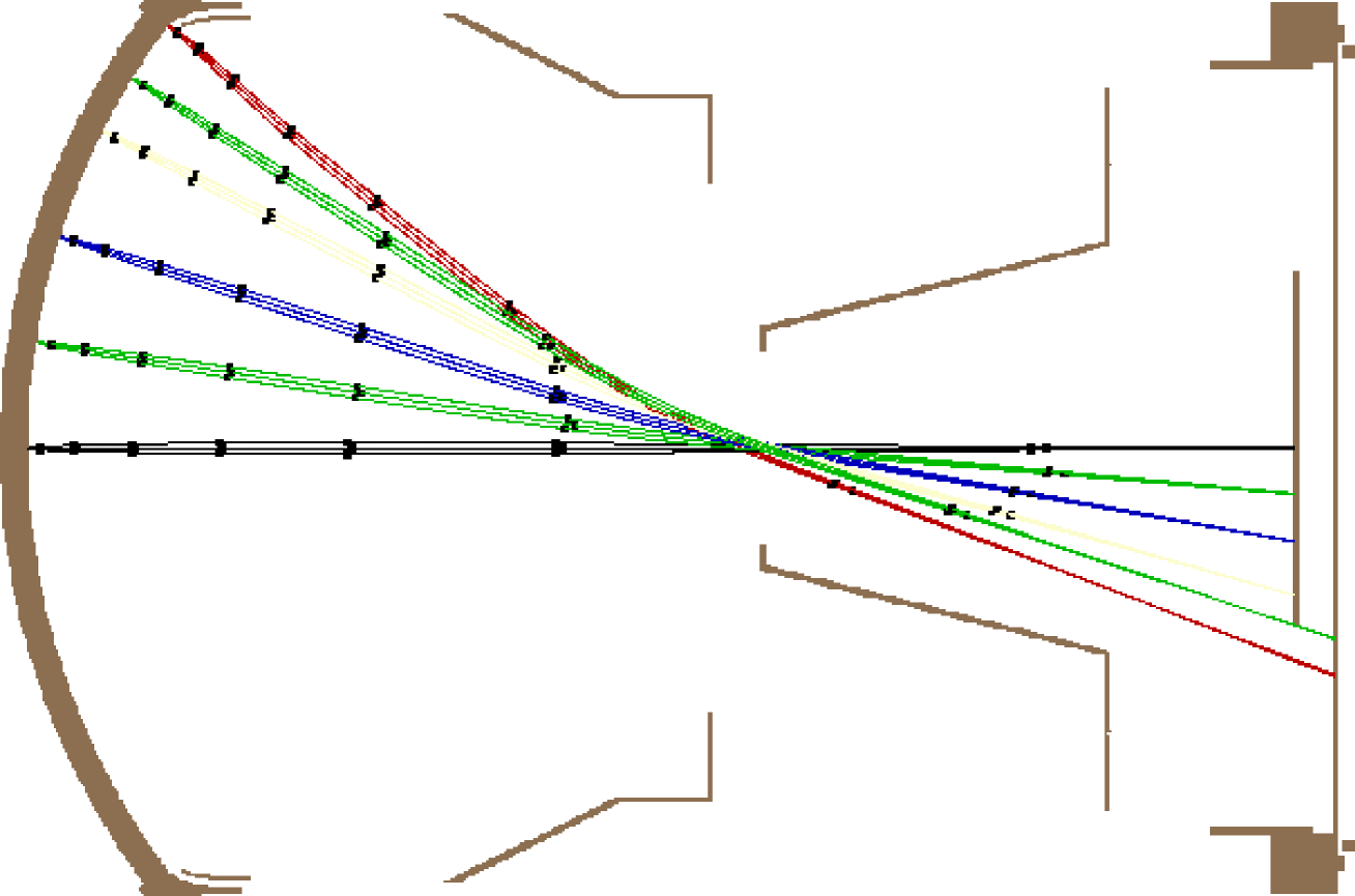
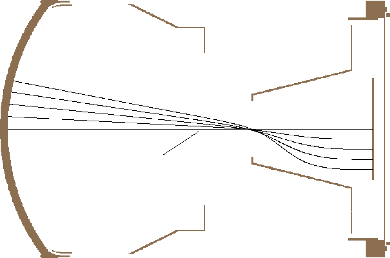
With the first HPD design to be presented, see Fig. 1, the idea was to extend the sensitive photocathode surface almost to the physical edge of the device. This 5-inch HPD was designed particularly for the hexagonally close packed Ring Imaging Cherenkov detectors of the LHCb experiment [2, 3]. Its size and the demagnification factor were determined from the size of the 2048-channel silicon-pad sensor (5-cm diameter) used for the detection of the photoelectrons and the required position resolution for Cherenkov photons. The radius of curvature of the spherically shaped entrance window was originally taken such that the center of curvature was placed close to the surface of the silicon sensor. This provides a very good mechanical stability, needed because of the thin window connection with the body of the tube. Further optimizations of the window curvature for the electron optics quality are still possible, but it turns out, as we shall demonstrate in some detail, that a very good result may be achieved already with the original curvature. However, the optimization of the tube length will be considered below.
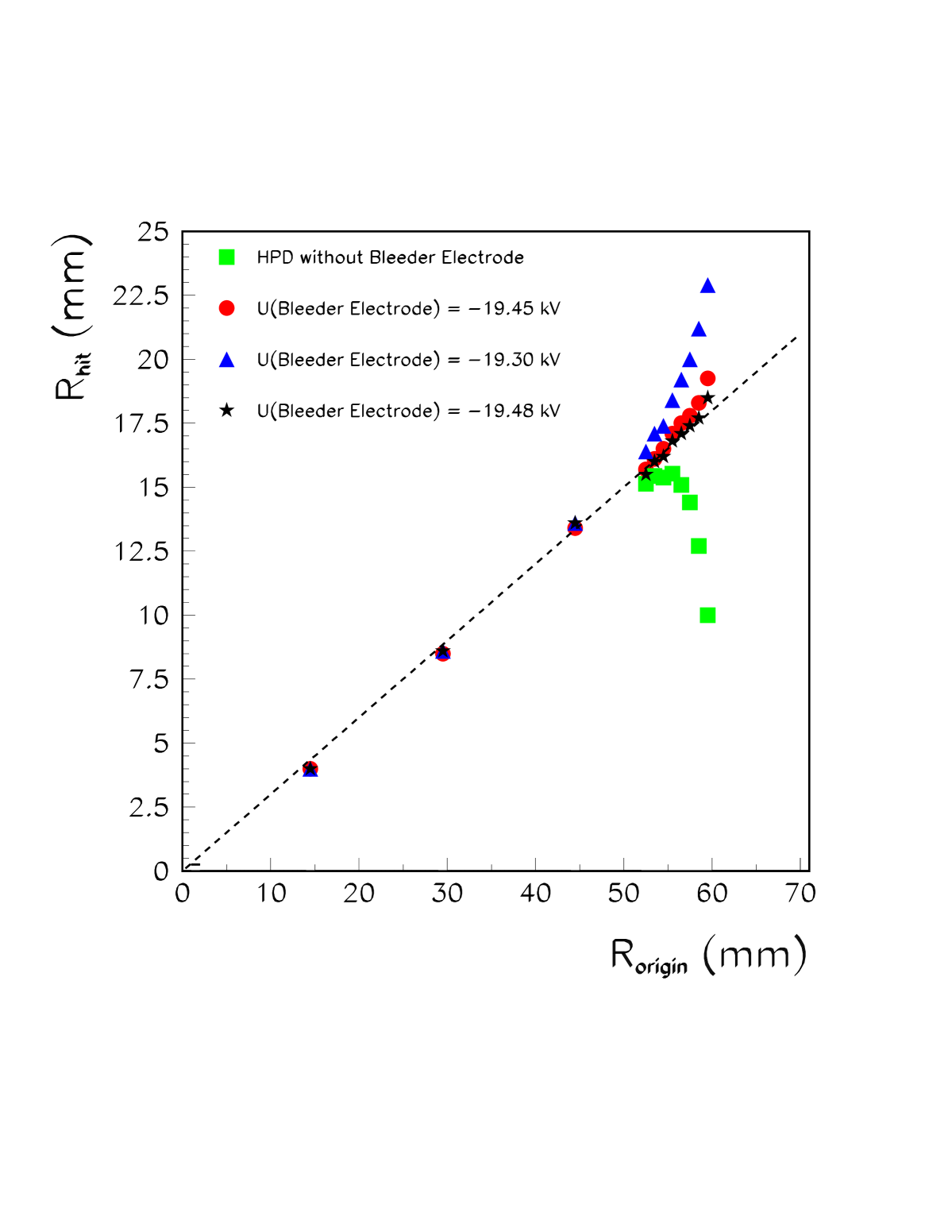
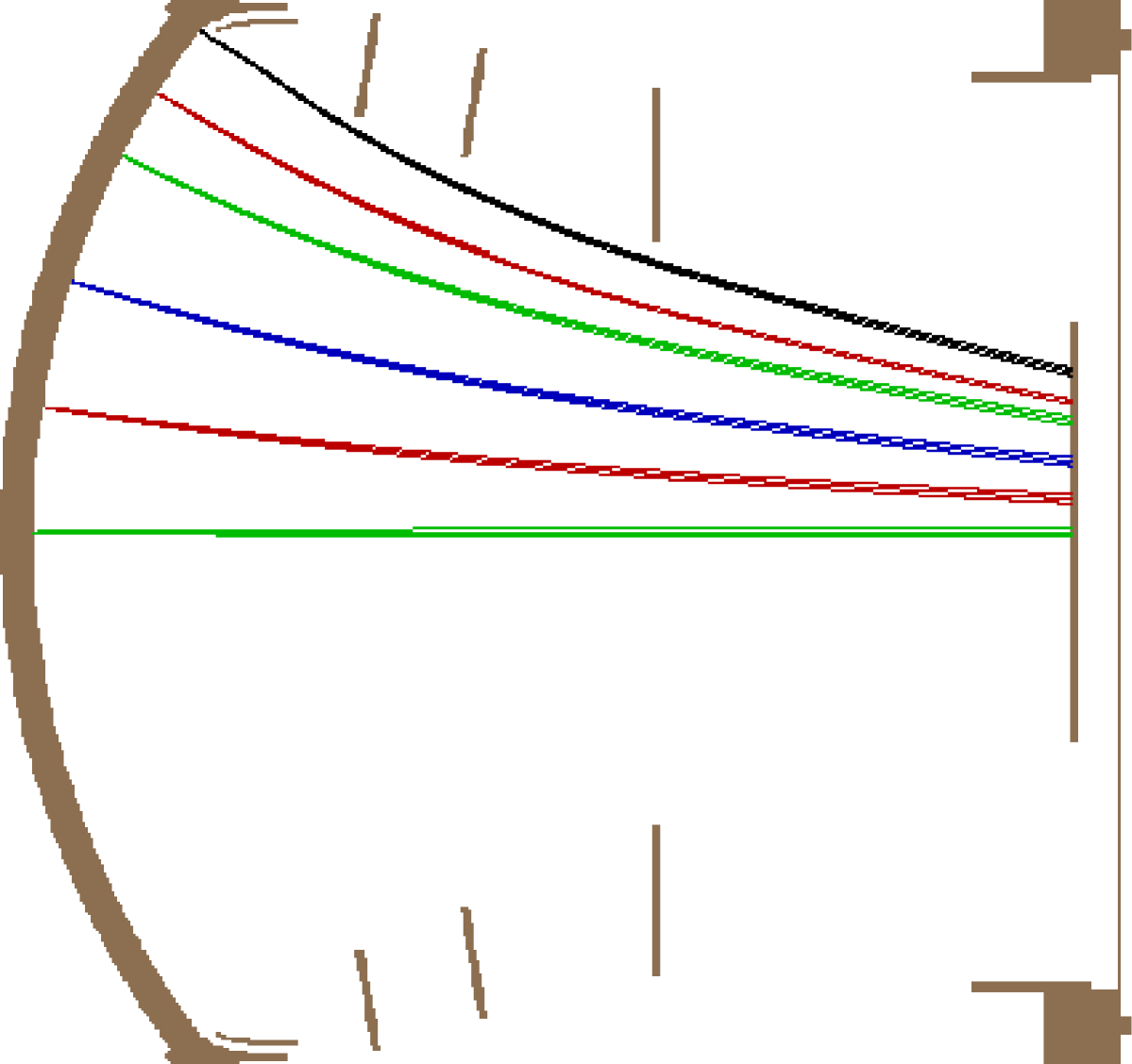
Electron focusing is demonstrated in Fig. 1 – photons (not shown in the figure) enter HPD from the left side, pass through the entrance window, and release photoelectrons from the photocathode on the interior of the window. Photoelectrons then undergo acceleration and electrostatic focalization towards the silicon-pad sensor, shown on the right side. Some example trajectories are presented in Fig. 1. A relatively smooth mapping between the image on the photocathode and the projected image on the silicon sensor has been achieved close to the axis of the tube but, evidently, mapping completely fails in the region close to the periphery of the tube where strong image folding is present (the square symbols in Fig. 2). Although the physical shape of this HPD has been successfully optimized for close packing by maximal extension of the photocathode towards the periphery, the device demonstrates unacceptably large functionally dead area.
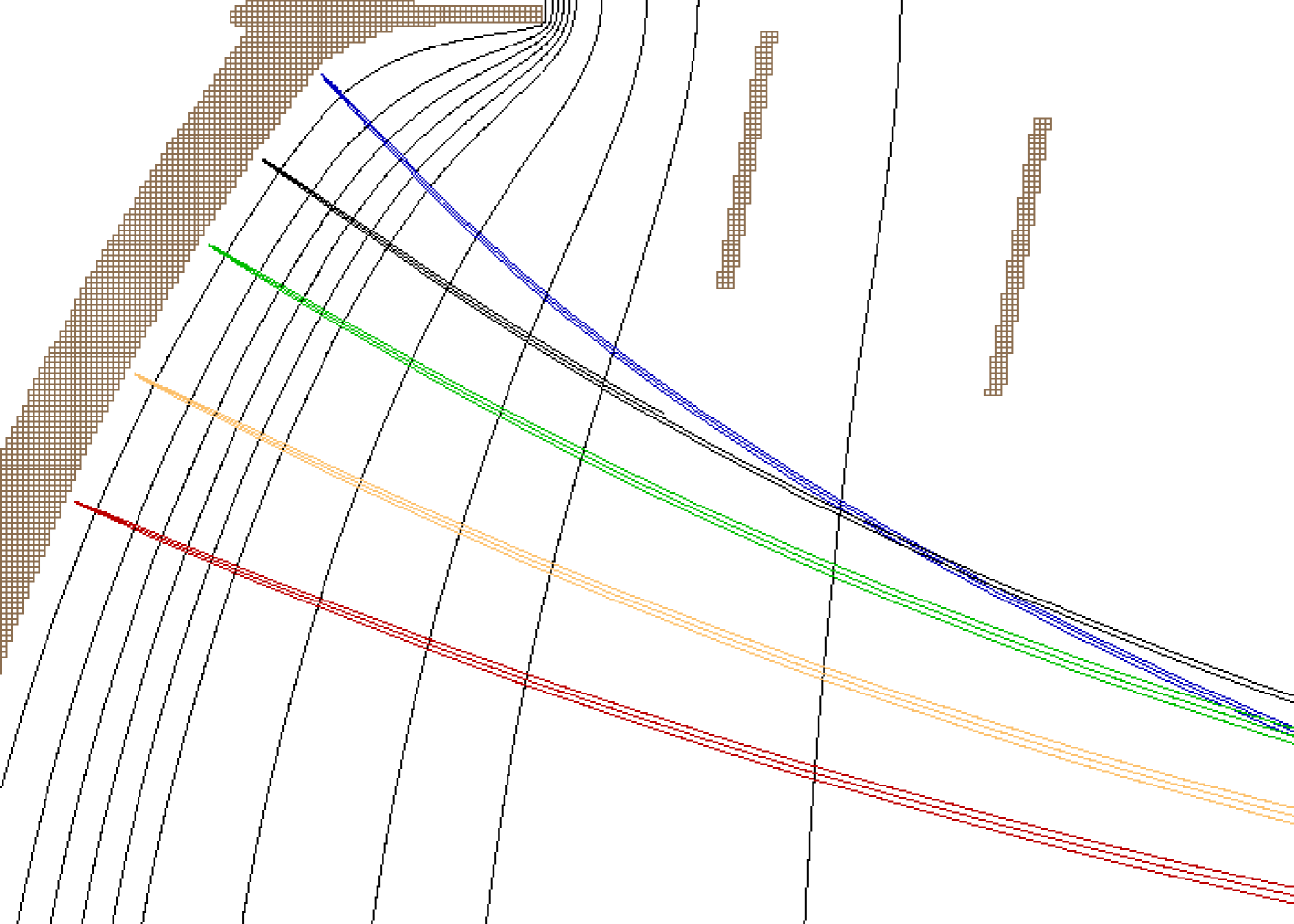
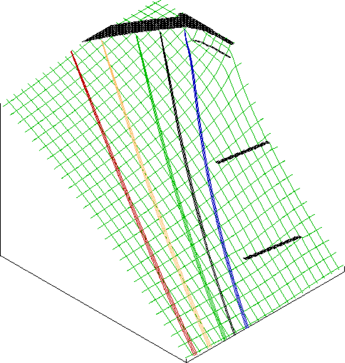
The reason for the failure becomes evident from Fig. 3 and Fig. 4. There is a rapid change in the curvature of the equipotential surfaces as the periphery of the tube is approached, apparently due to the shape of the conducting surface. Photoelectrons emitted from that region are directed too strongly towards the center of HPD.
To fix this problem, one should reduce the curvature of the potential distribution. Ideally one would prefer to have equal curvature across the entire photocathode, and would be therefore tempted to redesign the window supporting structure. However, for constructional reasons - precisely those related to the achievement of the minimum constructional dead area - this was not possible.
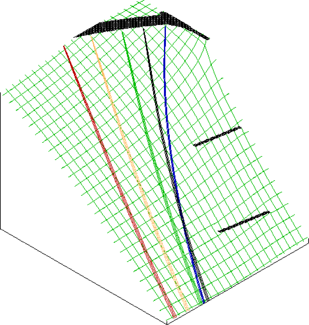
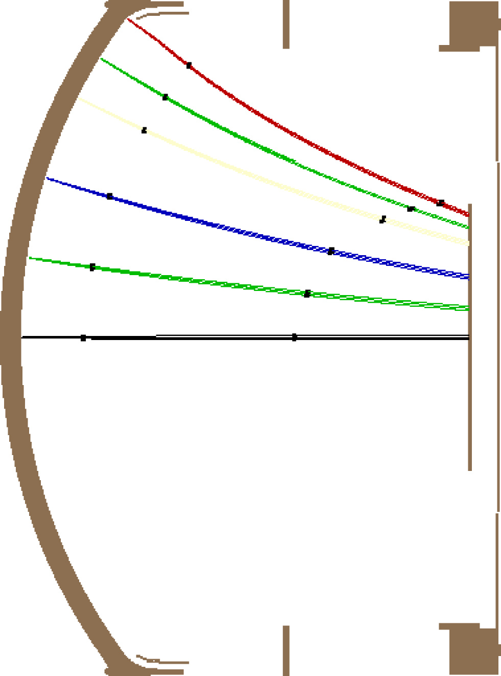
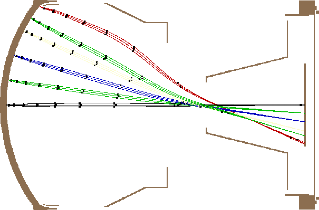
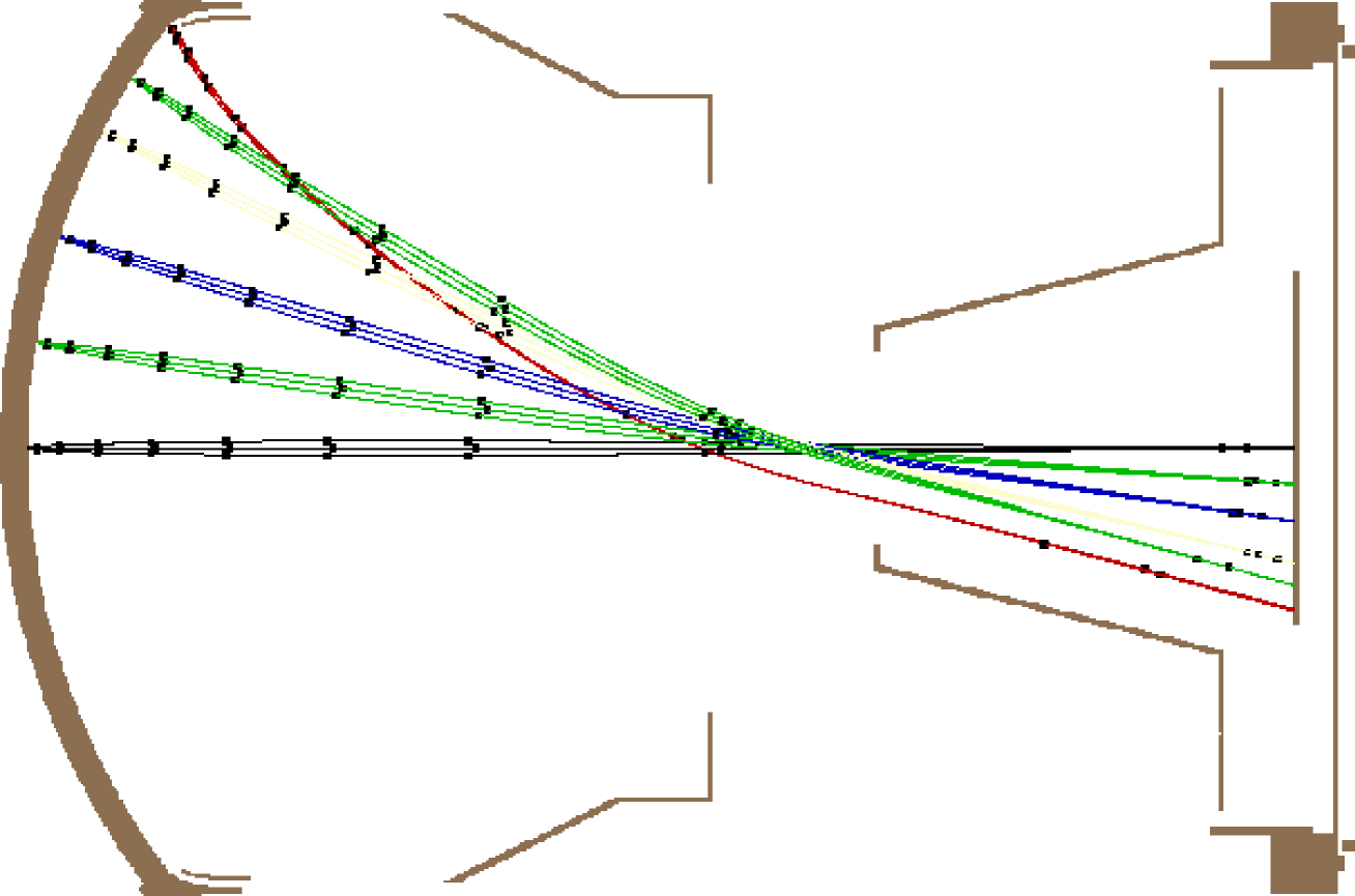
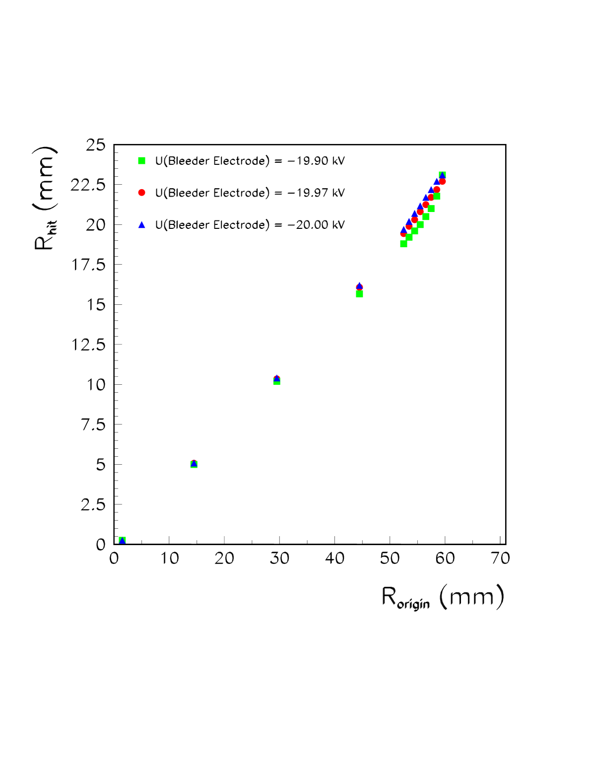
We have searched therefore for another solution with the idea to reduce the field curvature by “conducting” some of the potential lines out from the tube, around the metallic window support. The solution was found in the creation of a slot which acts as a “potential-conductor”, see Figs. 5, 6 and 7. The slot was created by the insertion of a specially shaped new electrode, the so called “bleeder electrode” (since it bleeds off the “unwanted” field). The unwanted potential lines are indeed conducted away through the slot between the bleeder electrode and the body of the tube, and the resulting field in the problematic peripheral region has evidently lost its strong curvature, as presented in Figs. 5, 6 and 7. The mapping quality is presented in Fig. 2, as a function of the potential on the bleeder electrode. Since the acceptance is extended out to 60 mm away from the tube axis, 63.5 mm being the outer tube radius, about 89% of the total photocathode surface now maps correctly onto the silicon-pad sensor, and the functionally dead area got considerably reduced.
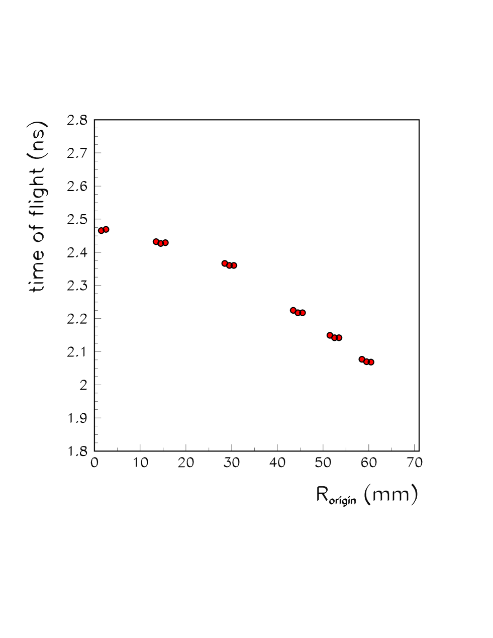
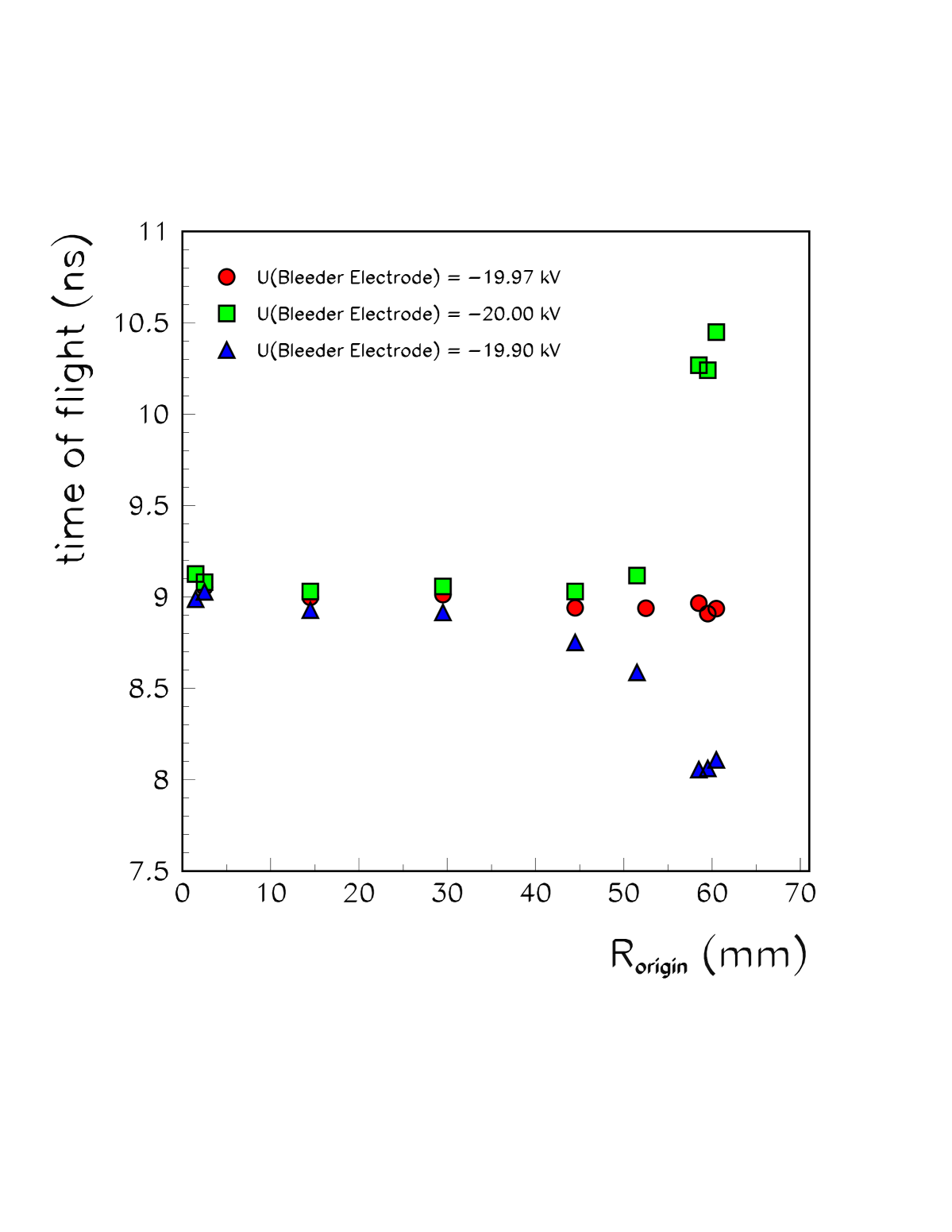
It is interesting to note that a considerably shorter HPD, but of the same transverse size and entrance window, may provide the same imaging accuracy, consider Fig. 8. The advantages of this short HPD are a very short time of flight, as presented in Fig. 9, and a weaker sensitivity to the residual magnetic field. The time of flight is not only short, but the spread corresponding to a given point of origin on the photocathode is very narrow, as demonstrated by triplets in Fig. 9. The weak sensitivity to the residual magnetic field is due to the lower B L and to the very rapid electron acceleration, since the magnetic radius of curvature is proportional to the velocity. A certain disadvantage may be the relative closeness of the electrodes with a large potential difference.
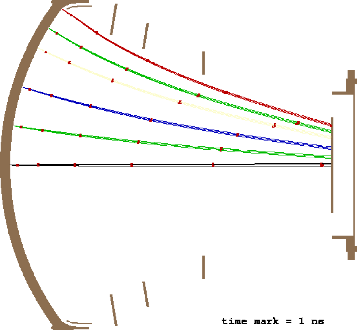
Excellent imaging properties achieved by this method are equally welcome in stand-alone devices. Therefore the same method has been applied in the design of the 20-inch HPD tube (see Fig. 10) for the AQUA-RICH neutrino experiment, proposed for the CERN–Gran Sasso neutrino beam programme [4]. These HPDs are supposed to be placed in a array with a large distance between units. The AQUA-RICH HPDs should detect Cherenkov ring images from charged products of neutrino interactions in a huge water tank. The silicon sensor will consist of 85 pixels. A stronger demagnification (relative to the LHCb design) was needed because of the large tube diameter, and the tube length was therefore increased accordingly. The first focusing electrode that follows the bleeder electrode plays in this design a very active role in appropriate imaging, which was not the case in the LHCb tube design, where essentially the same imaging performance could be achieved without any focusing electrode except the bleeder (the other electrodes served to assure a stable potential distribution).
Timing properties, i.e. the distribution of arrival times of photoelectrons to the semiconductor sensor, will be very important for the AQUA-RICH experiment since it is supposed to supply detailed information about the real-time Cherenkov pattern development. Due to the strong potential gradient close to the photocathode, this device has a relatively good timing characteristics. The time evolution of the electron trajectories is indicated by 1 ns time marks along the trajectories in Fig. 10. Note however that further optimization is possible. For example, a shorter tube should be considered, like the short tube in Fig. 8.
To summarize, we have presented HPD designs essentially based on the application of the bleeder electrode. By suitably changing the field configuration in the critical region close to the periphery of the photocathode, the bleeder electrode provides correct imaging and considerably reduces the functional dead area in large imaging HPDs. Out of the three designs presented, the long tube for LHCb has been produced and recently successfully tested [11], and the HPD tube for AQUA-RICH has been ordered for production in a downscaled size (10-inch diameter) for real physics tests.
The same method has been successfully applied in yet another HPD design, which incorporates also the protection against the positive ion feedback. That is the second topic of this publication and the subject of the following section.
3 Ion Feedback Protection in Large-area Imaging HPDs
The presence of positive ions in the PMT and HPD vacuum tubes presents one of the main drawbacks, particularly in applications with high background or low signal photon rates, like in Atmospheric Cherenkov Telescopes (ACT) in the field of gamma ray astronomy [5, 9, 10], or in Cherenkov neutrino experiments. Acceleration and subsequent dumping of positive ions into a photocathode leads both to creation of noise through electrons released, and to a rapid damage of the photocathode [5, 9, 10]. In high-vacuum tubes the vast majority of positive ions do not originate from residual gas, but rather from the the surface of the anode, upon the impact of accelerated photoelectrons. Apart from Oxygen and Hydrogen atoms from adsorbed water, Cesium atoms are particularly abundant because they usually spread inside tubes during and after the manufacturing (activation) of photocathodes.
General solution to the problem of the feedback of positive ions emerging from such processes was found [5] in the insertion of a permanent electrostatic potential barrier in front of the surface of the Photo Diode (PD) in HPDs, or in front of the first dynode in PMTs. This method was originally proposed [5] to modify the small (2-cm-diameter) single-pixel Intevac HPD [10]. In this paper we demonstrate that the same idea may be successfully applied to a large area imaging HPD.
The potential barrier is created by the so called “barrier electrode” placed in front of the silicon sensor and kept at a positive potential with respect to the anode. The potential needed to establish a sufficiently high potential barrier strongly depends on the size of the opening in the barrier electrode, which is in turn determined by the width of the beam of photoelectrons, in order to allow a free passage of the photoelectrons. The wider the opening, the higher the positive potential on the electrode.
The HPD tube designed for LHCb, presented in the previous section, Fig. 7, is characterized by proximity focusing electron optics (i.e. the diameter of the electron pattern shrinks progressively down to the silicon sensor size). Due to the very wide electron pattern the barrier electrode should have a wide opening, and that would require a very high positive potential in order to establish the barrier effect. The proximity focusing design is therefore very unsuitable for the implementation of the positive ion feedback protection.
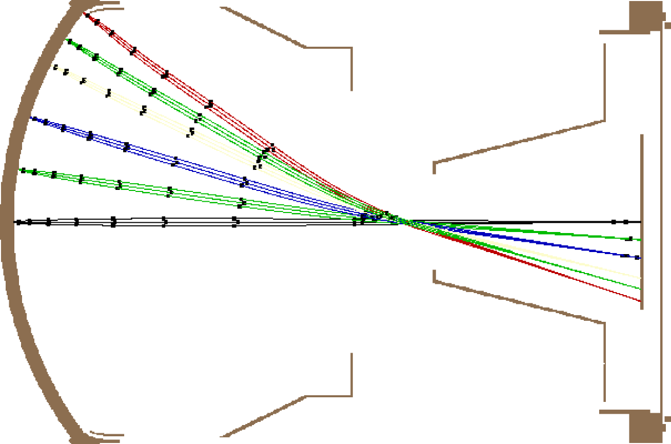
However, a modified HPD design (see Fig. 11) with the so called “cross-focusing” electron optics provides the means to apply our positive ion protection method. The point is that electron trajectories originating at any point on the photocathode cross in a single place about the middle of the tube, and it is possible to insert a barrier electrode with a very narrow opening, placed just at the crossing point of the electron trajectories. There are many reasons why this electrode should have a conical shape, as in Fig. 11, like e.g. the need to separate the connection to the power supply outside the tube as far as possible from the throughput of the neighbour electrode with opposite polarity.
3.1 Cross Focusing Electron Optics
Before we turn to the discussion of the functionality of the conical electrode for ion protection, let us first review its functionality in electron optics of a cross focused device. Roughly speaking, the conical electrode acts as a “zoom” in the electron lens. The space enclosed by the conical electrode is practically field-free, see Fig. 12, and therefore from its entrance onwards electrons keep their velocities and directions until they hit the anode surface. The zooming functionality of the conical electrode is related precisely to this feature - the electron velocity vectors are “frozen” after they enter the cone, consider Figs. 12, and placing the cone entrance earlier or later along the electron trajectories freezes the electron momenta with more or less divergence, respectively. This feature is demonstrated in Fig. 13 – the conical electrode was moved closer to the photocathode, and consequently the image got magnified.
To achieve a good “image sharpness”, on the other hand, one should optimize the potential on the electrode placed between the conical electrode and the photocathode.
In the development of the cross focused tube, presented in Fig. 11, we started from the proximity focused HPD design, presented in Fig. 7, and introduced a number of significant modifications. We kept the same diameter (5-inch) and shape of the entrance window in order to be able to use the same parts in tests. However, the tube got considerably elongated to provide the means for the cross-focusing electron optics. The conical electrode and the electrode closer to the photocathode were introduced.
The bleeder electrode stayed in place with essentially the same functionality. The effects of potential variations on the bleeder electrode are presented in Figs. 14, 15, 16 and 17. It is evident that the bleeder electrode plays again an important role in the shaping of the trajectories, although the mapping is more robust than in the proximity focusing HPD. A very coherent time evolution for all trajectories may be achieved by careful tuning, as demonstrated in Figs. 11 and 17. Compared to the short proximity focused HPD (Figs. 8 and 9), the optimized cross focused device offers a much more coherent time evolution over the entire area, while the total time of flight is around four times longer, and the time spread for a given point of origin is wider.
3.2 Ion Feedback Protection
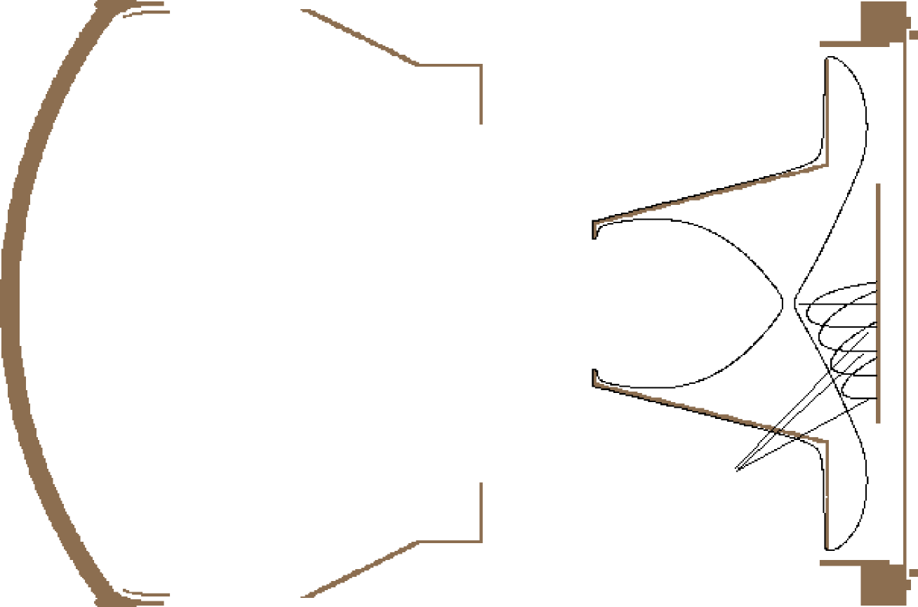
To demonstrate the positive ion feedback, in Fig. 18 the conical electrode is kept at the anode potential i.e. the ion protection was set “off”. Trajectories of singly charged positive ions are shown, emerging with energies of 44 eV at normal incidence from the anode surface on the right side of the figure, and moving towards the photocathode on the left side.
Note that the angular and energetic distributions of positive ions are, to our best knowledge, unknown. We have worked out a scheme how to perform a measurement of those quantities, using actually a tube with a barrier electrode, but since the results are not yet available, we are currently using a rough estimate that the ions could reach an energy of around 40 eV. Once the actual energy will be measured, it will be straightforward to repeat the simulations and find the optimal potential settings.
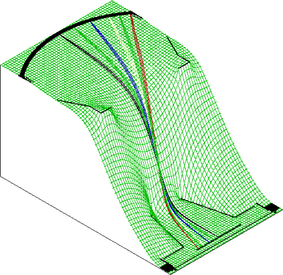
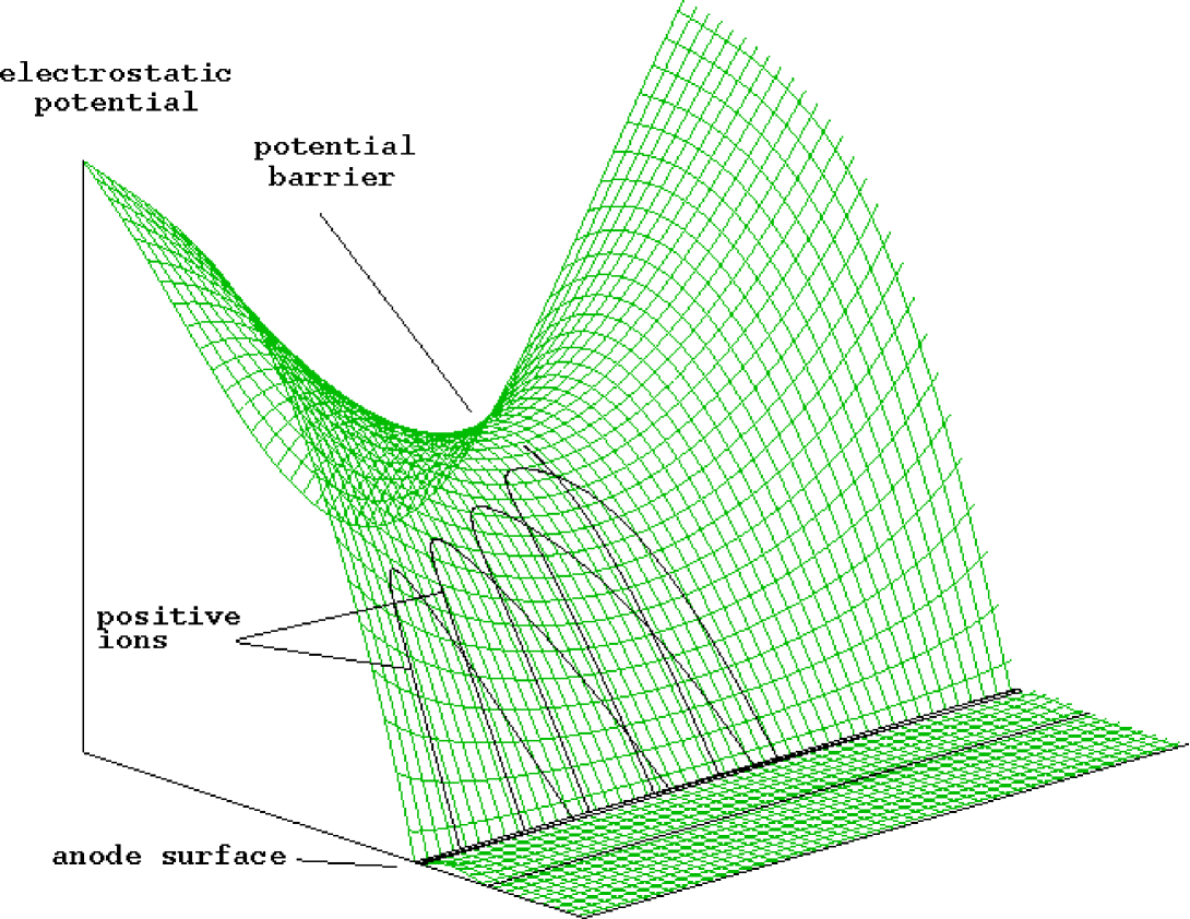
The conical electrode starts to play the role of the “barrier electrode” [5] when a sufficiently high positive potential is applied. As demonstrated in Fig. 19, monotonous decrease of the potential for positive particles towards the photocathode breaks down, and a potential barrier (for positive particles) is created in front of the anode. This barrier prevents positive ions from penetrating further towards the photocathode and solves the ion feedback problem. For more clarity the potential distribution in front of the anode plane is shown in a magnified view in Fig. 20. Trajectories of singly charged positive ions are simulated with identical initial conditions like before. Ions of energy lower than the barrier always get repelled back from the barrier and never can reach the photocathode.
As argued already in [5], the precision of the potential on the barrier electrode which is required for stable electron focusing is not a critical issue – variations of even 10% on the potential will leave the electron focusing essentially unchanged. An independent, very common voltage supply may be therefore used to bias the positive conical barrier electrode.
Apart from providing for the positive ion protection, this tube is characterized by a much narrower spread of photoelectrons on the silicon-pad sensor and therefore with a superior imaging performance. There are also other benefits from the conical barrier electrode: (i) it will capture a large fraction of electrons back-scattered from the semiconductor sensor, and (ii) to some extent it will protect the anode area from pollution during (and after) the manufacturing of the tube, in particular in case of in-situ photocathode activation.
Our cross focusing HPD should be tested soon – it was designed in a way to be rather easily assembled from the elements of the proximity focusing HPD (Fig. 7) (entrance window with photocathode, cylindrical body, base plate and silicon sensor), which have already been produced.
The presented cross focused HPD, with all its virtues, seems to be a very good choice for Atmospheric Cherenkov Telescopes, Cherenkov neutrino detectors and in general in applications which reqire good imaging, low noise and coherent timing.
4 Conclusions and Outlook
Imaging Hybrid Photon Detectors (HPD) have been developed for integration in large area imaging Cherenkov detectors to be used in high energy physics and astrophysics. The presented designs have been developed in particular for experiments MAGIC, LHCb and AQUA-RICH. Apart from a very good imaging performance, the presented HPDs comprise protection against positive ion feedback and(or) minimal dead area. A detailed discussion of the underlying innovations was presented. We have introduced a new electrode (“bleeder”) which modifies the field configuration in the critical region close to the periphery of the photocathode, thus providing correct image mapping and minimization of the dead area in large imaging HPDs. Three proximity focused and one cross focused HPD design were presented that are based on the application of the bleeder electrode. The latter design also incorporates the protection against the positive ion feedback, a feature very important for Atmospheric Cherenkov Telescopes, but also for Cherenkov neutrino detectors.
So far, the presented HPD designs have already evolved beyond the
design stage:
(i) Proximity focusing HPDs for
LHCb (Fig. 7) were produced and
tested recently [11]. The results fully
confirm the presented design.
(ii) Cross focusing HPDs (Fig. 11) should be assambled (essentially from
parts of proximity HPDs) and tested soon.
(iii) Half-sized
(10-inch diameter)
HPDs for AQUA-RICH (Fig. 10)
are in production
for real physics tests in a water container exposed to
a muon or hadron beam at CERN [12].
Acknowledgments
Very stimulating discussions with Enrico Chesi, Eckart Lorenz, Dario Hrupec, Eugenio Nappi, Guy Paić and Jacques Seguinot are gratefully acknowledged. I am particularly grateful to Tom Ypsilantis who also strongly motivated this publication.
References
-
[1]
R. Kalibjan, IEEE Transactions on Nuclear Sciences,
June 1966, p. 51.
J.M. Abraham, Advances in electronics and electron physics, 1966, p 671.
P. Chevalier, Nucl. Inst. Meth. 50 (1967) 346.
J. Fertin et al., IEEE Transactions on Nuclear Sciences, Vol. NS 15 June 1968.
R. DeSalvo et al., Nucl. Inst. Meth. A315 (1992) 375. - [2] D. Ferenc, New Detectors – 36th Workshop of the INFN Eloisatron Project, Ettore Majorana Centre for Scientific Culture, Erice, Trapani, Sicily, November 1-7, 1997. To appear in the proceedings, World Scientific, also physics/9810004.
- [3] J. Seguinot, ibid.
-
[4]
T. Ypsilantis, J. Seguinot and
A. Zichichi, CERN-LAA/96-13.
T. Ypsilantis et al., Nucl. Inst. Meth. A371 (1996) 330. - [5] D. Ferenc, D. Hrupec and E. Lorenz, accepted for publishing in Nucl. Inst. Meth. A (1999), also physics/9811028.
- [6] J.A. Barrio et al., The MAGIC Telescope Design Study, Max-Planck-Institut für Physik, München, Internal report MPI-PhE/98-5, 1998.
- [7] D.A. Dahl, 43rd ASMS Conference on Mass Spectrometry and Allied Topics, May 21-26 1995, Atlanta, Georgia, pg 717.
- [8] R. Winston, J. Opt. Soc. Amer. 60, 245-247, 1970.
- [9] R. Mirzoyan, E. Lorenz, D. Petry, and C. Prosch, Nucl. Inst. Meth. A387 (1997) 74.
- [10] S. Bradbury, R. Mirzoyan, J. Gebauer, E. Feigl, and E. Lorenz, Nucl. Inst. Meth. A387 (1997) 45.
- [11] LHCb report 98-037.
- [12] T. Ypsilantis, AQUA-RICH 3 Ton test (private communication).