Concentrator of laser energy
for thin vapour cloud
production near a surface
P.I.Melnikov111Corresponding author. Address: Lavrentyev av. 11, BINP, 630090 Novosibirsk, Russia. Phone: +7(383)2359 285. Fax: +7(383)235 2163. E-mail: melnikov@inp.nsk.su, B.A.Knyazev, J.B.Greenly
Novosibirsk State University, 630090 Novosibirsk, Russia.
Budker Institute of Nuclear Physics,630090 Novosibirsk, Russia.
Laboratory of Plasma Studies, Cornell University, Upson Hall 369,
Ithaca, NY 14853.
———————————————————-
Abstract
A novel scheme is presented for production of a thin ( mm) uniform vapor layer over a large surface area ( cm2) by pulsed laser ablation of a solid surface. Instead of dispersing the laser energy uniformly over the surface, a modified Fabry-Perot interferometer is employed to concentrate the laser energy in very narrow closely-spaced concentric rings. This approach may be optimized to minimum total laser energy for the desired vapor density. Furthermore, since the vapor is produced from a small fraction of the total surface area, the local ablation depth is large, which minimized the fraction of surface contamination in the vapor.
Key words: laser evaporation, thin gas layer formation.
———————————————————–
1 Introduction
In principle, an ideal plasma-based ion source for an ion beam would provide a perfectly uniform, very thin layer of fully ionized plasma with a single ion species, at a temperature low enough to introduce negligible beam divergence. For magnetically insulated ion diodes for light-ion inertial fusion drivers, these criteria in practice would require a plasma layer less than 1 mm thick, with areal density greater than 1015 cm-2, uniform to within 10 to prevent unacceptable perturbation of the plasma surface smoothness causing beam divergence, and ion temperature below 50 eV. Pulsed-laser ablation of vapor from a surface is one possible means of providing a gas layer to form such a plasma, before application of the high-voltage pulse. This gas layer can be ionized either by near-surface discharge in the applied field, or in advance, by means of photoresonance laser ionization of the vapor [1]. By this technique one could obtain space-charge-limited current from all the anode plasma surface and, consequently, to eliminate additional sources of the ion beam divergence [2].
Work at Sandia National Laboratories [3] has produced anode vapor layers in this way, by dispersing laser energy over the desired anode surface area. High uniformity and purity is very difficult to achieve by this method, especially since the areal density of vapor desired is rather small, but the area is large ( cm2), requiring the laser energy to be dispersed uniformly to an energy density not far above the threshold for ablation, a regime in which vapor production is a strong function of laser energy density and surface contaminants may dominate vapor production.
In this paper we investigate an alternative scheme in which the laser is intentionally concentrated into a series of concentric narrow rings. Vapor is produced in these rings, which are closely enough spaced ( mm) that the ablated clouds merge to an adequately uniform layer of 0.5 mm thickness. The concentration allows the evaporation to be done at a higher, optimum power density for a particular laser and anode material, so that the overall laser energy is minimized (see [4, 5]). In addition, for a given total amount of vapor, the depth of ablation in the rings is larger than for uniform illumination by the ratio of total area to ring area, so surface contaminants to bulk material ratio could be much less in comparison with a case of the disperse radiation distribution at a lower power density.
2 Principle of operation
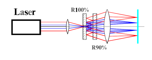
The scheme of the concentrator is shown in Fig.1. The concentrator is based on a Fabry-Perot interferometer. A laser beam is introduced by an input focusing lens into the interferometer through a small hole in the first mirror. The output lens focuses the light after the interferometer to produce concentric thin rings at the target surface. Most of the energy of the laser concentrates in these rings on the surface, except only the central part of the beam which is lost by reflection back through the hole. The device including the input lens, the interferometer, and the output lens we will refer to as a concentrator. The power density in the narrow rings is chosen to be high enough to evaporate surface material efficiently. The amount of material evaporated per unit laser energy peaks at a particular optimum value. If this value is chosen for the rings of illumination, a desired area-averaged vapor density is produced with minimum laser energy.
We will use the following terms: , are reflection coefficients for first and second mirrors (, ); , are transmission coefficients (defined as ); is the wavelength of laser generation, is the distance between mirrors.
Consider a ray of the laser beam focused by the input lens with intensity on the input of the concentrator and angle to the axis. The intensity of this ray behind the back mirror is . The intensity of the reflected part of the ray after the first reflection from the front mirror and passing through the back mirror is , and after th reflection – . These rays interfere at the focal plane of the output lens. The electric field amplitude of the th is equal to
| (1) |
where
| (2) |
is the phase difference of subsequent rays. The number of the interfering rays N is limited by the radius R of the interferometer, and resulting the amplitude on the target is , or
| (3) |
where . Consequently the distribution of the intensity at a limited is
| (4) |
For large enough (for small ) this expression reduces to the well known Airy-function
| (5) |
The intensity in maxima increases rapidly with and close to 1. For this case , and
| (6) |
For the distribution of laser radiation over the target surface “intensities” and in the above written formulae have to be replaced by the radiation power densities and , which are functions of radius and azimuthal angle on the target (). In contrast to a conventional Fabry-Perot interferometer, where the power density cannot be higher then the initial power density, for the concentrator the power density in the peaks can be much higher than the incident power density. For example, if and , , e.g. the concentrator multiplies the peak power density one hundred times.
There may be substantial advantages of such an energy distribution for surface gas layer production. The maximum intensity for all the rings would be equal if the initial laser beam is uniform, and the averaged power density over any area of dimension larger than the ring spacing is equal to , so that for const the distribution of averaged power density from the concentrator would be constant. The multiplication factor (if ) gives not only the power density multiplication in the rings but also the ratio of total area to the illuminated ring area.
3 Vapor cloud production: a practical example
The concentrator described can be applied to thin vapor cloud production near an anode surface of ion accelerator. Figure 2 shows an example of using of the concentrator in a magnetically insulated ion diode. The upper diagram shows direct illumination of the anode for simplicity, while the lower diagram shows a way to remove the concentrator from the ion beam path.
Let us introduce the parameters that must be involved in the calculation process. , are the inner and outer radii of the anode, is the distance between illuminated rings on anode surface, is power density needed to evaporate the anode material. The parameters of the concentrator are: , , the foci of the input and output lenses of the concentrator; , , the angles of the input rays that are directed by the output lens to the and radii; the radius of the interferometer; , the distance between the mirrors of the interferometer; , the distance between the output mirror and the focus of the input lens; , the radius of the hole; the multiplying factor; , the energy density on the output mirror surface. The laser parameters are: , the generation wavelength; , the bandwidth of laser generation; , the pulse duration; , the pulse energy.
We now estimate the parameters needed for realizing the scheme. We choose the COBRA ion diode [6] as an example. For this diode, cm, cm. We desire cm, for adequate uniformity of the vapor layer on a distance cm from the anode surface. For evaporation by 10 ns laser pulse of an aluminium target we choose MW/cm2 [7], for optimum efficiency of vapor production. Experiments on vapor cloud production (see [8]) show that for every target there is a range near an optimal power density where it is possible to obtain low-ionized cold vapors without the laser-induced breakdown. It is significant also that near this value of power density the amount of evaporated material and the velocity of vapor boundary are only weakly dependent on power density [9]. Thus the vapor layer could be more uniform than the initial laser power density . We will use the value m for the output lens focus, which would work in the configuration of Fig.2a for the present COBRA diode. Fig.2b shows a possible arrangement in a focusing diode geometry. The value of may be adjusted to avoid interference of optical elements with the ion beam. We assume a ruby laser with wavelength nm. For definiteness we put , but this figure might be varied.
The value defines the distance between mirrors. Actually, the maxima of power density (6) correspond to the zeros of . So two nearby maxima differ by angle when
| (7) | |||
The distance between mirrors is
| (8) |
The angles and are related to the and by . The distance between input lens focus point and output mirror surface may now be defined
| (9) |
and the hole radius is
| (10) |
The required radius of the interferometer can be determined as the radius at which the laser beam with the biggest angle is attenuated by a factor of e-2.
| (11) |
The number of interfered rays is for this interferometer radius.
We estimate the bandwidth of laser generation that is allowable to provide such narrow rings. The bandwidth must not lead to widening of the ring more than the width of the half height of the power density. From (2) and (6) we get
| (12) | |||||
The last value is close to a theoretical limit and impose strong requirement on the laser spectrum.
The main critical parameter of the concentrator is the energy density in the center of the output mirror surface. The mirror must be of high quality to be not destroyed by the intense laser beam.
| (13) |
This value is not too high, but the local energy density can be 3 times more due to interference effect. So the mirror must withstand the energy density of 11 J/cm2. Mirrors of such quality are available [10].
The total energy of laser can be calculated from the formula J. Only 40 of the energy is used in the evaporation, because of noncorrespondence of the solid circular laser beam and the hollow annular anode surface. It is more efficient to use an annular laser beam. A beam with such a structure can be produced by a Nd laser with nonstable resonator. Use of 1.06 m light leads to an increase of concentrator size (see (8, 9, 10, 11)): cm, cm, cm, cm. But the energy density on the output mirror surface would decrease (see (13)) J/cm2.
Using the 2nd harmonic of Nd laser generation gives twice smaller size (see (8, 9, 10, 11)): cm, cm, cm, cm. However, the energy density becomes four times higher (see (13)), and reaches a rather high value J/cm2. To use the concentrator in such a regime would require a mirror that would not damaged by the energy density J/cm2. This value is over the damage threshold for the best mirror coatings [10]. But it is possible that the mirror coating can withstand this energy density because averaged energy density is less 12 J/cm2, and the value above damage threshold is reached only in very thin rings of of thickness that would provide fast heat diffusion over the surface due to thermal conductivity.
4 Conclusion
The production of a very uniform, thin vapor layer above a solid surface by laser ablation is a difficult problem. We have suggested a method of distributing laser energy in a series of narrow, high intensity rings that could be advantageous in producing vapor efficiently, and, probably, with minimum sensitivity to surface contaminants and laser intensity variation. If this concentrated vapor production can be allowed to expand and merge into a uniform layer, these advantages might be realized. We leave aside of this paper consideration of the problem of possible small-scale non-uniformity of the gas layer produced with the concentrator as well possible anode plasma instability. Obviously, at first the technique suggested has to be verified experimentally, and the anode layer parameters must be measured.
5 Acknowledgments
This work was supported, probably in part, by U.S. Civilian Research and Development Foundation, Award RP1-239, and Russian Ministry of General and Professional Education.
References
- [1] H. Bluhm, B.A. Knyazev, P.I. Melnikov et al., Tech. Phys. Lett. 23 (1997) 343.
- [2] S.A.Slutz, Phys. of Fluids B 4 (1992) 2645.
- [3] R.V. Stinnet, J.E. Bailey, K.W. Bieg et al., Proc. of the 8th Intern. Conf. on High-Power Partical Beams, Novosibirsk, USSR, 1990, p.167.
- [4] B.A. Knyazev, S.V. Lebedev, and V.N. Snytnikov, Book of abstracts of All-Union Conf. on Low-Temperature Plasma Physics, Kiev, USSR, 1979, p.339. (in Russian).
- [5] B.A. Knyazev, S.V. Lebedev, and K.I. Mekler, Sov. Phys. Tech. Phys. 31 (1986) 773.
- [6] E. Krastelev, B.A. Knyazev, F. Lindholm et al., Proc. of the 11th Intern. Conf. on High-Power Particle Beams, Prague, Czech Republic, 1996, p.1143.
- [7] B.A. Knyazev, B.I. Kulikov, S.V. Lebedev, and E.P. Fokin, Preprint 80–208, Institute of Nuclear Physics, Novosibirsk, USSR, 1980. 29 p. (In Russian).
- [8] B.A. Knyazev, Abstracts of 8th Workshop on Atomic and Molecular Physics for Ion-Driven Fusion, Heidelberg, Germany, P.67 (1997)
- [9] N.G. Basov, V.A. Boiko, V.A. Dement’ev et al., Soviet Physics JETP 24 (1967) 659.
- [10] C. Fournet, B. Pinot, B. Geenen et al., Proc. SPIE 1624 (1991) 282.