Carbon Coated Gas Electron Multipliers
Abstract
Gas electron multipliers (GEMs) have been overcoated with a high resistivity 10 amorphous carbon layer. The coating avoids charging up of the holes and provides a constant gain immediately after switching on independent of the rate. The gain uniformity across the GEM is improved. Coating opens the possibility to produce thick GEMs of very high gain.
1 Introduction
The gas electron multiplier (GEM) [1,2] has proven to be a very attractive new device especially in combination with MSGCs. Splitting the amplification in two steps allows to reduce the MSGC voltage to values safely below sparking thresholds. The functionality of GEM-MSGCs has been demonstrated in hadronic beams [3] and in magnetic fields up to 1 Tesla. Gains in excess of 103 have been reached with GEMs [4] which open the perspective to replace the MSGC by a simple passive anode structure. Many interesting results have been published by the CERN group [4,5] and the large scale application of the GEM is foreseen in the HERA-B experiment.[3,6]
Like in all gaseous detectors, the maximum gain of GEMs is limited by discharges. Breakdown may occur through streamer discharge due to large space charge densities. Gains of about 103 can be achieved in one amplification step depending on the strength and shape of the electric field [7]. In the case of GEMs or similar devices a large amplification gap with low gain per unit length is preferable to a high condensed field. Another limiting factor is a possible non-uniformity of the field caused by sharp electrode edges or variable resistivity of insulating surfaces. The latter certainly limit the maximum distance of the two conducting planes. Indirect indications for surface discharges in GEMs have been reported [8]. The inhomogeneities in the surface resistivities can be avoided by coating the surface with a slightly conducting layer, a procedure which has been very successful with MSGCs. Furthermore such a coating eliminates gain variations due to polarization of the plastic and to charging up by ion deposition. These unpleasant effects have been observed in MSGCs on plastic substrates [9] and led to abandon these devices. To avoid charging-up it was proposed to add a small amount of water to the gas [2] which, however, may lead to fast aging [3]. The CERN group reported measurements using GEMs with cylindrical holes where gain variations were totally absent [4].
The following measurements have been performed with GEMs which were overcoated with an amorphous carbon layer. The behavior before and after the coating was compared.
2 The setup
The GEMs have been produced at the CERN workshop and coated by a standard industrial CVD process111a-Si:C:H:N coating : Fraunhofer Gesellschaft für Schicht und Oberflächentechnik, Braunschweig, Germany. The active GEM area was (type M) and (type L). The thick polyimide foil was covered on both sides by copper, some of the foils have only copper because of a second etching process. GEM foils of type M have a square hole lattice with a pitch of , GEMs of type L have a staggered structure with a minimum distance between two holes (center to center) of . The hole diameters varied between and at the narrowest part of the Kapton and to at the copper layers. A top view of typical GEM foils is shown in figure 1.
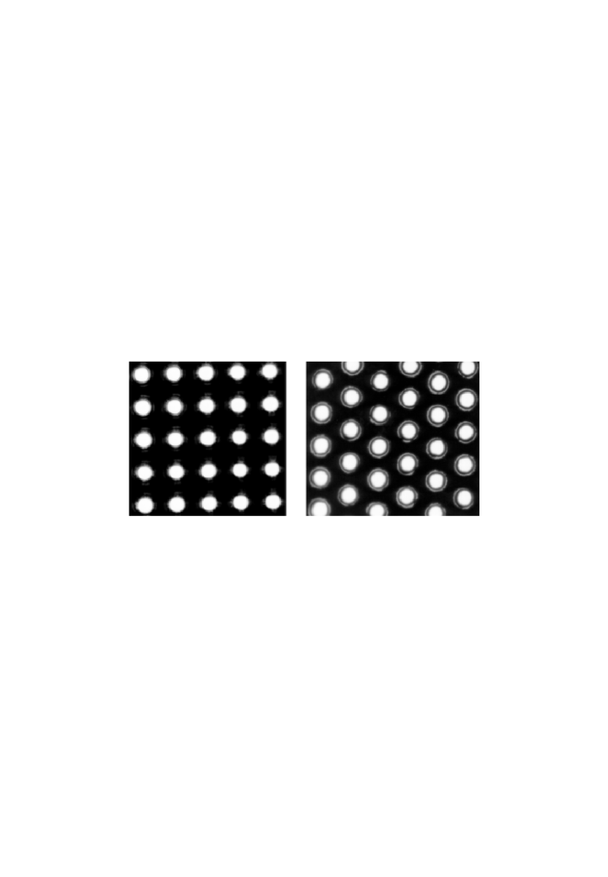
The quality of the first small series (type M) was exceptionally poor with large variations of the hole diameters of about and many defects. All the other GEM foils we investigated were of high quality like those shown in the figure.
The GEMs were glued onto G10 frames and inserted in MSGCs constructed in such a way as to allow an easy exchange of the GEMs. With the gluing of the GEMs onto frames special care has to be taken to the flatness of the GEMs. Variations in the distance between MSGC structure and GEM foil lead to large gain variations.
The MSGC structure had pitch, the anodes and cathodes were and wide. The gas volume of height was subdivided into two equal halves by the GEM. We operated the MSGC+GEM with a gas mixture of Ar/DME of 50:50, a variable GEM voltage below and a drift field of about . The MSGC anodes were grounded. The voltages were chosen such that the drift field below the GEM foil was slightly higher than above. The chamber was irradiated with Fe-55 and an source (Ra-226).
The active area of the MSGC+GEM was scanned with a computer controlled moveable table and a collimated Fe-55 source.
3 Results
3.1 Electrical properties of the GEMs
We have measured the electric resistance of the GEMs before and after the coating. The electrical resistance of the small GEMs was about before and after the coating. The apparent resistivity of the uncoated polyimide increases by about one and a half orders of magnitude during the polarization process of about one day duration. Figure 2 compares its variation with time to the coated version which is completely stable. Notice the different scales.
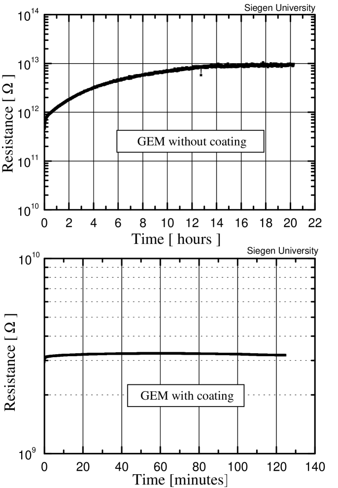
For the larger GEMs (type L) the resistance before coating was about . The reason for the higher resistance compared to the small GEMs is not fully understood. A reason may be a different polyimide material or different processing. After the coating the resistance of the large GEMs was of the order of (The resistivity of the coating was increased to reduce dark currents.)
3.2 Energy resolution
As mentioned before, the GEMs of the first small series (type M) show large variations of the hole diameters. For this reason the energy resolution of the uncoated GEMs of this type is rather poor. This is illustrated in Figure 3 where the iron spectrum is compared to that of the coated GEM. In both cases the irradiated area is about . Scanning with a strongly collimated source we measured gain variation by a factor two whereas they are in the range of about 10% for the coated GEM (Figure 4).

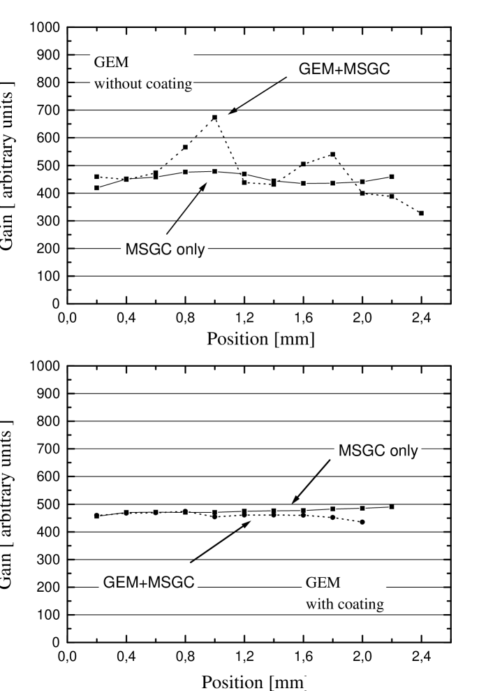
The superior behavior of the coated GEM is probably explained by its more homogenous field.
The large high quality GEMs (type L) showed comparable energy resolutions and gain variations before and after coating.
3.3 Gain stability
For the uncoated GEMs drastic gain variations due to polarization of the Kapton and to charging up by ion deposition are observed. Figure 5

shows the gain as a function of time. The gain increases by about a factor of two within 40 hours after switching on the HV. To disentangle the effects of polarization and charging-up we have measured the gain across the active GEM area after different time intervals. The GEM was irradiated at a fixed position near its center. The results are displayed in Figure 6.
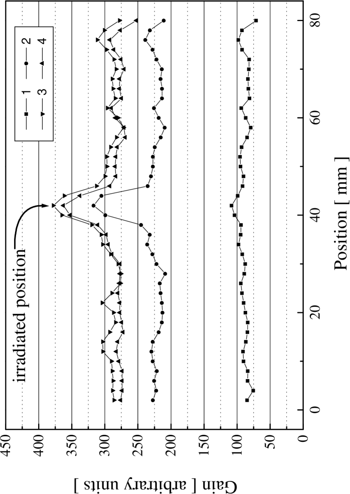
Initially the gain was rather uniform across the GEM (curve 1). After hours (curve 2) the gain has globally increased but at the irradiated spot an additional 40% increase is observed. The uniform gain increase of the whole GEM is explained by polarization of the polyimide whereas the additional local increase at the irradiated spot is due to charging-up by ion deposition. The gain remains high for several days after the source has been removed.
The gain of coated GEMs is nearly stable directly after switching on the HV. This is illustrated in Figure 7.
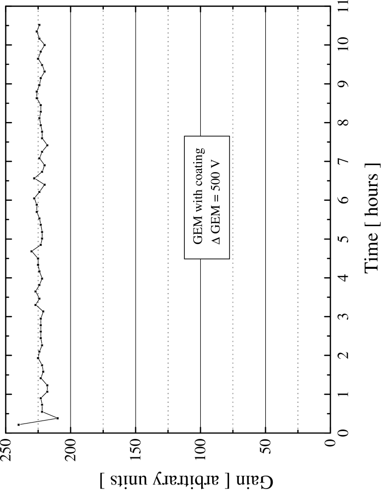
3.4 Maximum achievable Gain
Figure 8 shows the gas amplification as a function of the cathode voltage for different constant GEM voltages.
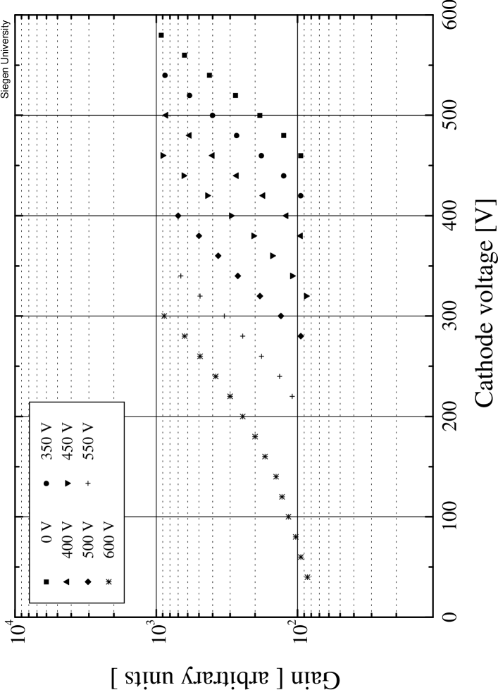
The leftmost curve is obtained with a cathode voltage of the MSGC of 50V only which is needed solely to direct the electrons towards the anodes. The GEM can safely be operated at gains of a few hundred. Both the coated and uncoated GEMs start to produce discharges at amplification factors above 1000 (Figure 9).

The discharges do not destroy or modify the performance of the GEM.
3.5 Stability of the coating
A coated GEM has been irradiated at a GEM voltage of with an source (Ra-226) of per spot size for several days without any deterioration, no discharges were observed. A long term aging test is still required. However, experience with MSGCs indicate that coating should rather improve the long term stability of gaseous detectors.
4 Conclusions and outlook
Coating of GEMs increases their performance. Instabilities due to charging up and polarization are avoided. For a series of small GEMs with unusually bad quality the coating improved the energy resolution and the spatial gain uniformity. This observation may allow to relax the quality requirement for the GEM production. The GEM quality of the larger GEMs (type L) we investigated is much superior and their energy resolution and spatial gain uniformity before coating was comparable to that of the coated GEMs.
At present we are studying GEMs with a thick polyimide layer. These foils were produced at Moscow Lebedev Institute. Their first attempt to etch the hole structure lead to a very bad quality. The copper sticks into the holes thus the maximum achievable voltages are limited by discharges. However, gains in excess of a few 1000 can be reached. We expect a new series with a second etching step which should avoid discharges and allows to verify that the coating increases the maximum achievable voltages and gains. We further intend to apply the coating technique to a two-dimensional detector [10] where the holes of the CAT [11] are replaced by grooves.
Acknowledgement: We are very grateful to Dr. F. Sauli for providing us various GEM foils from the CERN workshop and for many critical comments to our results.
References
- [1] F. Sauli, Nucl. Instr. and Meth. A386 (1997) 531
- [2] R. Bouclier et al., Nucl. Instr. and Meth. A 396 (1997) 50-66
- [3] B. Schmidt, HD-PY-98-02, Subm. 36th INFN Eloisatron Project Workshop on New Detectors Nov. 1997
- [4] J. Benlloch et al., Vienna Wirechamber Conference 1998
- [5] F. Sauli, Vienna Wire Chamber Conference 1998
- [6] T. Zeuner, Nucl. Instr. and Meth. A392 (1997) 105
- [7] P. Fonte et al. submitted to Nucl. Instr. and Meth.
- [8] Y. Ivaniouchenkov et al., Symposium on Radiation Measurements and Applications, Ann Arbor (1998)
- [9] S. Schmidt et al., Nucl. Instr. and Meth. A337 (1994) 386
- [10] S. Keller et al., Vienna Wire Chamber Conference 1998
- [11] F. Bartol et al., J. Phys. III, France 6 (1996) 337