MUON COLLIDER: INTRODUCTION AND STATUS
Abstract
Parameters are given of machines with center-of-mass (CoM) energies of 3 TeV and 400 GeV but, besides a comment on neutrino radiation, the paper concentrates on progress on the design of a machine to operate at a light Higgs mass, assumed, for this study, to be 100 GeV (CoM).
INTRODUCTION
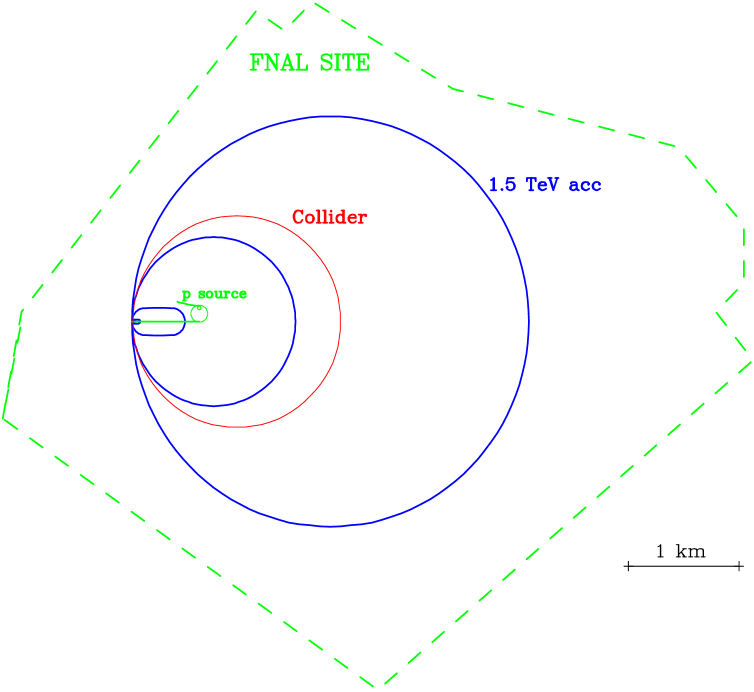
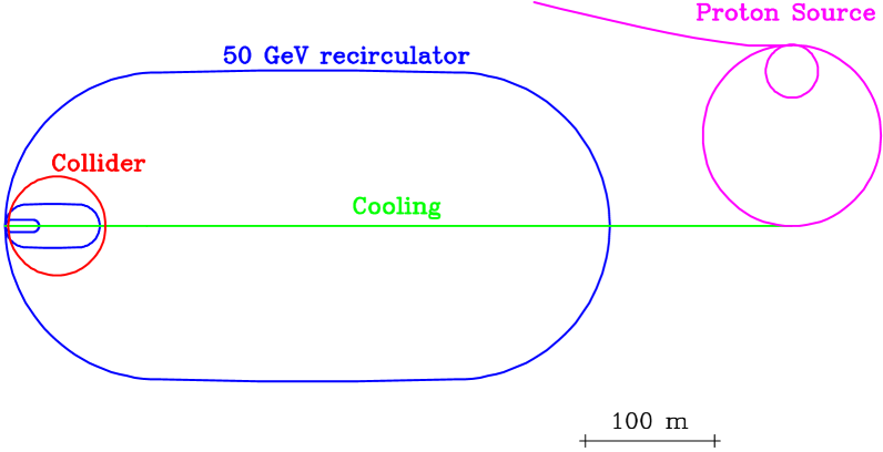
The possibility of muon colliders was introduced by Skrinsky et al.ref1 and Neufferref2 . More recently, a collaboration of over 100 members, lead by BNL, FNAL, LBNL, BNIP, University of Mississippi, Princeton University and UCLA has been formed to coordinate studies on specific designs. Work has been done on designs at a 3-4 TeV, 0.4-0.5 TeV and 100 GeVref3 ; ref4 ; ref5 ; ref6 ; ref6a . Tb. 1 gives the parameters of such colliders, and Figs. 1 and 2 show possible outlines of the 3 TeV and 100 GeV machines.
| (CoM) energy | TeV | 3 | 0.4 | 0.1 | ||
| p energy | GeV | 16 | 16 | 16 | ||
| p’s/bunch | 2.5 | 2.5 | 5 | |||
| bunches/fill | 4 | 4 | 2 | |||
| rep rate | Hz | 15 | 15 | 15 | ||
| p power | MW | 4 | 4 | 4 | ||
| /bunch | 2 | 2 | 4 | |||
| power | MW | 28 | 4 | 1 | ||
| wall power | MW | 204 | 120 | 81 | ||
| collider circ | m | 6000 | 1000 | 300 | ||
| depth | m | 500 | 100 | 10 | ||
| rms | % | .16 | .14 | .12 | .01 | .003 |
| 6D | 170 | 170 | 170 | 170 | 170 | |
| rms | mm mrad | 50 | 50 | 85 | 195 | 280 |
| cm | 0.3 | 2.3 | 4 | 9 | 13 | |
| cm | 0.3 | 2.3 | 4 | 9 | 13 | |
| spot | 3.2 | 24 | 82 | 187 | 270 | |
| tune shift | 0.043 | 0.043 | 0.05 | 0.02 | .015 | |
| Luminosity | 5 | 1.2 | 2 | |||
| (CoM) | 80 | 80 | 80 | 7 | 2 | |
| Higgs/year | 1.6 | 4 | 4 | |||
The original motive for considering muon colliders was the effective energy advantage of any lepton collider over hadron machines, together with the fact that muons, unlike electrons, generate negligible synchrotron radiation. As a result, a muon collider can be circular and much smaller than the current designs of linear electron colliders, and also much smaller than a hadron machine with the same effective energy.
In addition, a collider would have some unique physics advantages over an collider:
-
•
The direct coupling of a lepton-lepton system to a Higgs boson has a cross section that is proportional to the square of the mass of the lepton. As a result, the cross section for direct Higgs production from the system is 40,000 times that from an system.
-
•
Because of the lack of beamstrahlung, a collider can be operated with an energy spread of as little as 0.003 %. Furthermore, with the naturally occurring polarization it would be possible, by observing g-2, to determine the absolute energy to an accuracy of or betterref7 . It should thus be possible to use a collider to make precision measurements of masses and direct measurements of the Higgs width (assumed to be 2 MeV), that would be otherwise impossible, with an collider.
Machines with energies higher than 3-4 TeV, have significant beam current constraints from off site neutrino radiation limits. If the required luminosities are to be reached without unacceptable hazards, then significant improvements in muon emittance over the current base line values are needed. There is however reason to believe such improvements are achievable, and machines with a center of mass energy of 10 TeV and luminosities of and above may be possibleref8 . For energies below 3 TeV, for fixed muon currents, this radiation falls as the energy cubed, and it should be little problem for machines with energies of 1.5 TeV or less.
Recent work in the collaboration has concentrated on the lowest energy machine ( 100 GeV), whose energy is taken to be representative of the possible mass of a light Higgs particle. Such a machine would serve as a demonstration of Muon Collider technology, a needed step before high energy machines can be considered, and as a unique physics tool to make and study, if they exist, Higgs particles in the S-channel.
PROTON DRIVER
production rises approximately linearly with proton energy up to about 10 GeV after which it continues rising more slowly, but the requirement of very short bunches sets an effective minimum proton energy of about 16 GeV. The baseline specification used in Tb.2 is for a 16 GeV proton with a repetition rate of 15 Hz, protons per cycle in 2 or 4 bunches (depending on the collider energy), each with an rms bunch length of 1-2 ns. The total beam power is 4 MW. A design worked out at FNALnoble would involve: a) An upgraded linac (0.4 1 GeV); b) higher energy booster (8 16 GeV) and c) new pre-booster. Some parameters are given in Tb. 2.
| Linac | Pre-Booster | Booster | ||
| Final energy | GeV | 1.0 | 4.5 | 16 |
| Protons/bunch | ||||
| No of bunches | 2 | 2 | ||
| Rep. freq | Hz | 15 | 15 | 15 |
| Circumference | m | 180.6 | 474.2 | |
| Norm. 95% emit. | 200 | 240 | ||
| sp ch tune shift | .39 | .39 | ||
| Final field | T | 1.3 | 1.3 |
Another study had been done at BNLref9 that, while it did not quite reach the same beam power, involved far less upgrade: a) upgraded linac (0.2 0.6 GeV); b) increased AGS rep rate: 2.5 Hz.
In order to reduce the cost of the muon phase rotation section and for minimizing the final muon longitudinal phase space, it appears now that the final proton bunch length should be 1-2 ns.
An experimentref10 at the AGS has tested a method to generate such short bunches by rapidly bringing the tune of the machine near transition and allowing a strong phase rotation to occur. Bunches were shortened from 8 ns rms to 2.2 ns with initial longitudinal phase space similar to that specified in the above design. Shorter bunches are expected in later experiments with better control.
Another experimentlanl_inductor has used variable inductors to reduce the longitudinal space charge effects.
Target and Pion Capture
production is maximized by the use a well focused proton beam, small diameter target and a high Z target material. Tungsten, platinum or lead would be good, but the heating could not be easily removed and shock damage could be a problem. The use of a rapidly flowing liquid can solve the heating problem, but the shock could damage the enclosure, if one is used. We are thus considering the use of an open liquid jet. Such a jet has been testedref11 using mercury, although this was never exposed to a beam, and the jet did not move in a strong magnetic field, as required in our case. Theoretical studies of liquid metal flow in magnetic fields are underwayref12 ; ref13 , and the possibilities of using insulating liquids (e.g. PtO2, Re2O3) and slurries (e.g. Pt in water) are being considered.
If the axis of the target is coincident with that of the solenoid field, then there is a relatively high probability that pions produced at the start of the target will reenter, interact again later and be lost. The probability for such interactions is reduced, and the overall production rate increased (by about 60 %) if the target and proton beam are set at an angle (10-15o) with respect to the field axisref14 ; ref15 .
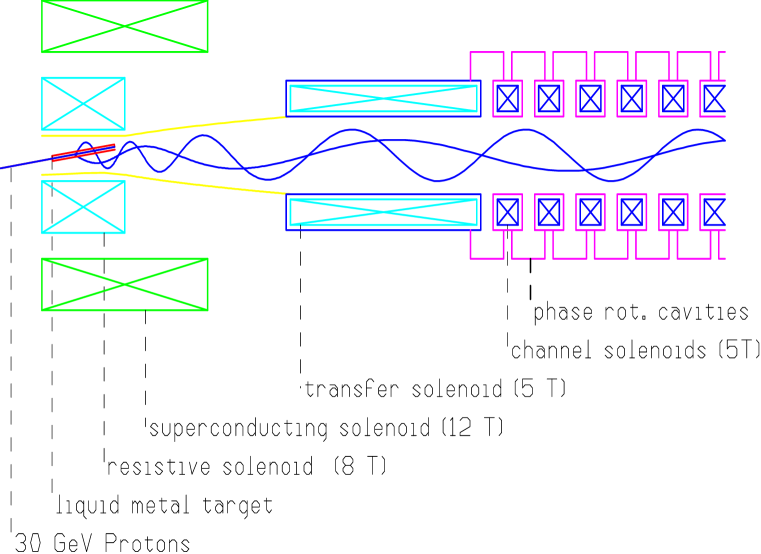
Three different codesarc ; mars ; dpmjet have been used to estimate yields and, despite detailed differences between them, overall production was very similar. In addition, the collaboration is involved in an AGS experimentexp910 to measure the yields. The production is peaked at a relatively low pion momentum ( 200 MeV/c), but has a very wide distribution: rms 100 %. The pion multiplicity, per 16 GeV proton, is about 2. At these low energies, the transverse momenta are of the order of 200 MeV/c. If a substantial fraction of these pions are to be captured, a very wide band system is required. A 20 T solenoid, 16 cm inside diameter is found to capture about half of all produced pions, and with target efficiency included, about 0.6 pions per proton emerge from the solenoid endref16 . Such a solenoid is well within the parameters of existing magnetsref17 . It would have a superconducting outsert, and an 8 MW water cooled copper insertref18 (see Fig. 3).
After capture, the 20 T solenoid is matchedsnake into a decay channel with 5 T fields and diameter of 30 cm.
Phase Rotation Linac
The pions, and the muons into which they decay, have an energy spread with an rms value of approximately 100 %. It would be difficult to handle such a wide spread in any subsequent system. A linac is thus introduced along the decay channel, with frequencies and phases chosen to deaccelerate the fast particles and accelerate the slow ones; i.e. to phase rotate the muon bunch. Tb.3 gives an example of parameters of such a linac. It is seen that the lowest frequency is 30 MHz, a low but not impossible frequency for a conventional structure.
| Linac | Length | Frequency | Gradient |
| m | MHz | MeV/m | |
| 1 | 3 | 60 | 5 |
| 2 | 29 | 30 | 4 |
| 3 | 5 | 60 | 4 |
| 4 | 5 | 37 | 4 |
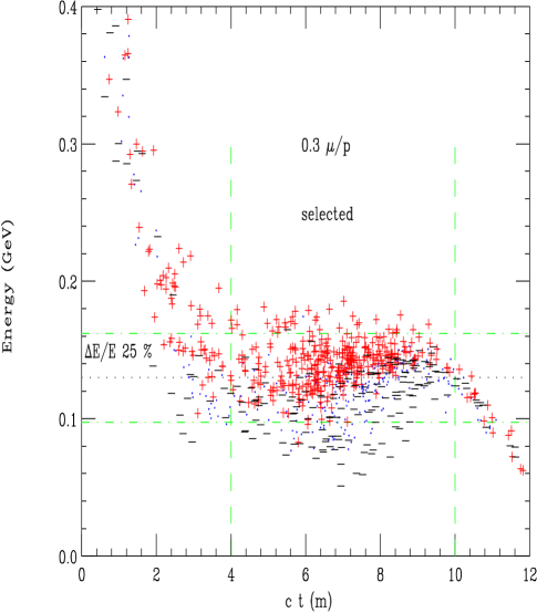
Fig. 4 shows the energy vs. c t at the end of the decay and phase rotation channel. A bunch is defined with mean energy 150 MeV, rms bunch length m, and rms momentum spread % (%, ) in the Monte Carlo studyref6 . The number of muons per initial proton in this selected bunch was 0.38, which can be compared with a value of 0.3 assumed in the baseline parameters.
Use of Both Signs
Protons on the target produce pions of both signs, and a solenoid will capture both, but the required subsequent phase rotation rf systems will have opposite effects on each. The baseline solution is to use two proton bunches, aim them at the same target one after the other, and adjust the rf phases such as to act correctly on one sign of the first bunch and on the other sign of the second.
A second possibility would be to separate the charges into two channels, and phase rotate them separately. However, the separation, probably using a bent solenoid, is not simple and would not be fully efficient. Whether a gain in overall efficiency could be achieved is not yet known.
Polarization
Polarized Muon Production
In the center of mass of a decaying pion, the outgoing muon is fully polarized (-1 for and +1 for ). In the lab system the polarization dependsref19 on the decay angle and initial pion energy. For pion kinetic energy larger than the pion mass, the average is about 20 %, and if nothing else is done, the polarization of the captured muons and phase rotated by the proposed system is approximately this value.
If higher polarization is required, some selection of muons from forward pion decays is required. Fig. 4, above, showed the polarization of the phase rotated muons. The polarization P, , and P is marked by the symbols and respectively. If a selection is made on the minimum energy of the muons, then greater polarization is obtained. The tighter the cut, the higher the polarization, but the less the fraction of muons that are selected. Fig. 5 gives the results of a Monte Carlo study.

If this selection is made on both beams, and if the proton bunch intensity is maintained, then naturally the muon bunch is reduced by the factor and the luminosity would fall by . But if, instead, proton bunches are merged so as to obtain half as many bunches with twice the intensity, then the muon bunch intensity is maintained and the luminosity (and repetition rate) falls only as .
One also notes that the luminosity could be maintained at the full unpolarized value if the proton source intensity could be increased. Such an increase in proton source intensity in the unpolarized case would be impractical because of the resultant excessive high energy muon beam power, but this restriction does not apply if the increase is used to offset losses in generating polarization.
Polarization Preservation
A paperref20 has discussed the preservation of muon polarization in some detail. During the ionization cooling process the muons lose energy in material and have a spin flip probability
| (1) |
where is the muon velocity divided by c, and is the fractional loss of energy due to ionization loss. In our case the integrated energy loss is approximately 3 GeV and the typical energy is 150 MeV, so the integrated spin flip probability is close to 10 %. The change in polarization is twice the spin flip probability, so the reduction in polarization is approximately 20 %. This loss is included in Fig. 5.
During circulation in any ring, the muon spins, if initially longitudinal, will precess by (g-2)/2 turns per revolution; where (g-2)/2 is . A given energy spread will introduce variations in these precessions and cause dilution of the polarization. But if the particles remain in the ring for an exact integer number of synchrotron oscillations, then their individual average ’s will be the same and no dilution will occur.
In the collider, bending can be performed with the spin orientation in the vertical direction, and the spin rotated into the longitudinal direction only for the interaction region. The design of such spin rotators appears relatively straightforward, but long. This might be a preferred solution at high energies but is not practical for instance, in the 100 GeV machine. An alternative is to use such a small energy spread, as in the Higgs factory, that though the polarization vector precesses, the beam polarization does not become significantly diluted.
COOLING
For a collider, the phase-space volume must be reduced within a time of the order of the lifetime. Cooling by synchrotron radiation, conventional stochastic cooling and conventional electron cooling are all too slow. Optical stochastic coolingref21 , electron cooling in a plasma dischargeref22 and cooling in a crystal latticeref23 are being studied, but appear difficult. Ionization coolingref24 of muons seems relatively straightforward.
Ionization Cooling Theory
In ionization cooling, the beam loses both transverse and longitudinal momentum as it passes through a material medium. Subsequently, the longitudinal momentum can be restored by coherent reacceleration, leaving a net loss of transverse momentum.
The approximate equation for transverse cooling (with energies in GeV) is:
| (2) |
where is the normalized emittance, is the betatron function at the absorber, is the energy loss, and is the radiation length of the material. The first term in this equation is the coherent cooling term, and the second is the heating due to multiple scattering. This heating term is minimized if is small (strong-focusing) and is large (a low-Z absorber).
The equation for energy spread (longitudinal emittance) is:
| (3) |
where the first term is the cooling (or heating) due to energy loss, and the second term is the heating due to straggling.
Energy spread can be reduced by artificially increasing by placing a transverse variation in absorber density or thickness at a location where position is energy dependent, i.e. where there is dispersion. The use of such wedges can reduce energy spread, but it simultaneously increases transverse emittance in the direction of the dispersion. Six dimensional phase space is not reduced.
Cooling Components
We require a reduction of the normalized transverse emittance by almost three orders of magnitude (from to m-rad), and a reduction of the longitudinal emittance by one order of magnitude. This cooling is obtained in a series of cooling stages. In general, each stage consists of two components:
-
1.
a material in a strong focusing (low) environment alternated with linac accelerators. These components will cool the transverse phase space.
-
2.
a lattice that generates dispersion, with absorbing material wedges introduced to interchange longitudinal and transverse emittance.
Simulations have been performed on examples of each component using the program ICOOLref25 which includes Vavilov distributions (with Landau and Gaussian limits) for dE/dx, and Moliere scattering distributions (with Rutherford limit). The only effects which are not yet included are space-charge and wake-field effects. Analytic vacuum calculations indicate that these effects should be significant, but not overwhelming. A correct simulation must be done before we are assured that no real problems exist.
Transverse Cooling
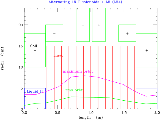
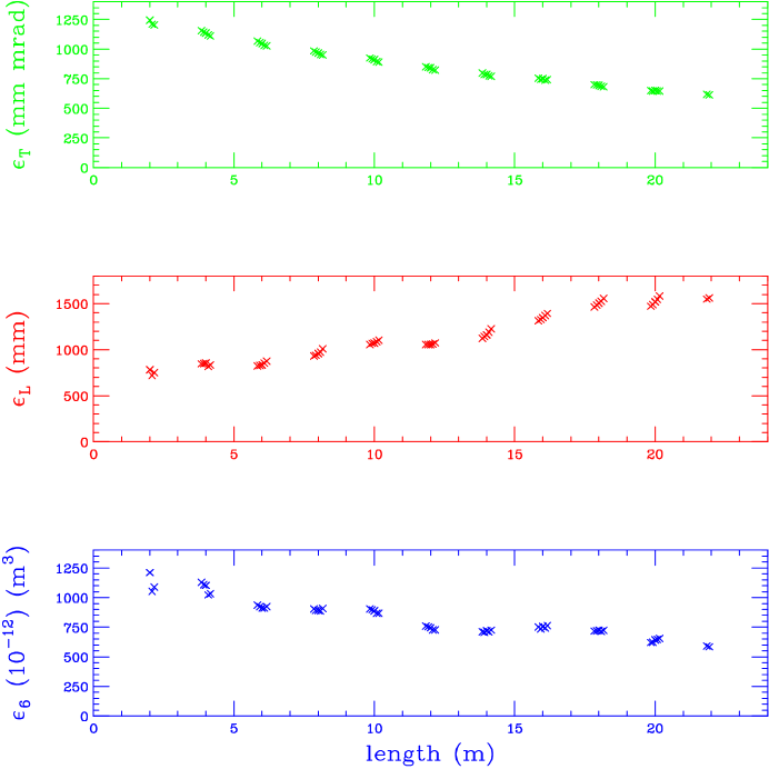
The baseline solution for the first component involves the use of liquid hydrogen absorbers in strong solenoid focusing fields, interleaved with short linac sections. The solenoidal fields in succesive absorbers must be reversed to avoid build up of the canonical angular momentum. Fig. 6 shows the cross section of one cell of such a system. The top plot in Fig. 7 shows the reduction of transverse emittance in 10 such cells (20 m); the middle one shows the increase in longitudinal emittance induced by straggling and the adverse dependence of dE/dx with energy; while the bottom one shows the overall reduction in 6-dimensional emittance. This simulation has been confirmed, with minor differences by the codes double precision GEANTpaul and PARMELAparmela .
Using 30 T solenoids at the end of a cooling sequence can attain a transverse emittance of 190 mm mrad and a six dimensional emittance of m3 (cf.280 mm mrad and m3, respectively required for a Higgs factory).
Other solutions, e.g. rapidly alternating solenoids and LiH absorbersfofo and current carrying Li rods have been and will continue to be studied, but do not appear to be required to meet the baseline parameters (see below).
Linac
The linacs used in the above simulations has a frequency of MHz and required an accelerating gradient (peak phase) of MV/m. The current designs use cavities separated by thin Be foils, or phase advanced per cavity, and powered in 3 of 4 separate interleaved side-coupled standing-wave systemszhao ; moretti . In order to reduce power source requirements the cavities may be operated at liquid nitrogen temperatures.
Longitudinal-Transverse Exchange
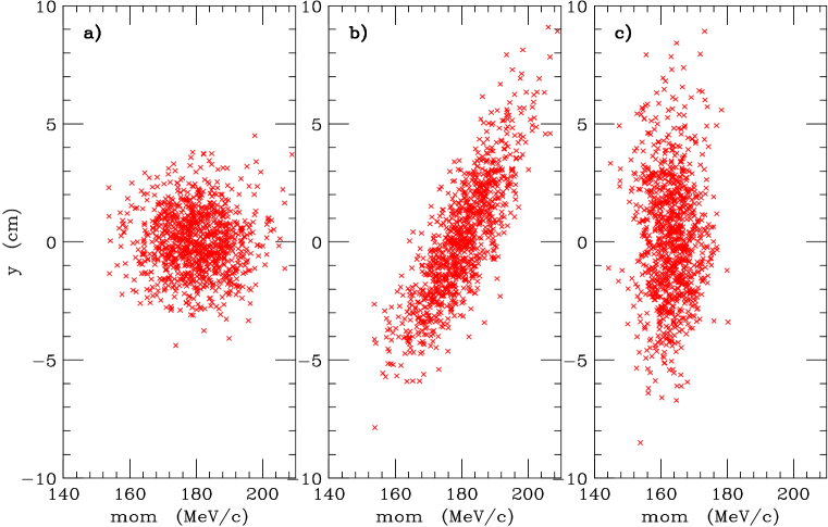
The exchange of longitudinal and transverse emittance requires dispersion in a large acceptance channel. One way of achieving this is in a bent solenoid. Fig. 8 shows transverse positions vs.their momenta: a) before the bend, b) after the bend, and c) after hydrogen wedges. The rms momentum spread in this example is reduced from MeV/c to MeV/c with an accompanying approximate equivalent increase in the x-y emittance.
Emittance exchange in solid wedges in the presence of ideal dispersion has also been simulated using SIMUCOOLdave . Dispersion generation by weak focussing spectrometersbalbekov and dipoles with solenoidswan are also studied.
Cooling System
The required total 6 dimensional cooling is about 106. Since a single stage, as illustrated above, gives a factor of 2 reduction, about 20 such stages are required. The total length of the system would be of the order of 500 m, and the total acceleration would be of the order of 6 GeV. The fraction of muons remaining at the end of the cooling system is estimated to be
In a few of the later stages, current carrying lithium rods might replace item (1) above. In this case the rod serves simultaneously to maintain the low , and attenuate the beam momenta. Similar lithium rods, with surface fields of T , were developed at Novosibirsk (BINP) and have been used as focusing elements at FNAL and CERNref26 ; ref27 . Cooling in beam recirculators could lead to reduction of costs of the cooling sectionbalbekov .
ACCELERATION
Following cooling and initial bunch compression, the beams must be rapidly accelerated. A sequence of linacs would work, but would be expensive, some form of circulating acceleration is preferred. At lower energies, the acceleration time is so short that any form of magnet ramping is probably impractical. The conservative option is to use a sequence of recirculating accelerators (similar to that used at TJNL), but fixed frequency alternating gradient acceleration (FFAG) is also being studiedref28 . At higher energies, it is probably more economical to use fast rise time pulsed magnets in more conventional synchrotronsref29 .
Scenarios
Tbs. 4 and 5 give an example of possible sequences of accelerators for a 100 GeV Higgs Factory and a 3 TeV collider. In both cases, following initial linacs, recirculating accelerators are used. Designsref30 have been made of multiple aperture superconducting magnets for use in recirculating acceleration. The use of such magnets was not assumed in the scenarios, but they would reduce the diameter of the recirculating accelerator ring and lower particle loss from decay.
In the high energy case, the final three stages use pulsed magnet synchrotrons. If only pulsed magnets were used the power consumed by a ring would be high and its circumference large, but a hybrid ring with alternating pulsed warm magnets and fixed superconducting magnets appears practical. In the example, the last two such rings are located in the same tunnel with differing ratios of pulsed to fixed magnets. The fixed magnets are superconducting at 8 T; the pulse d magnets are warm with fields that swing from - 2 T to + 2 T.
In both cases, except for the earliest stages, superconducting rf is employed. The reason for this, in the earlier stage, is that the instantaneous acceleration power requirement is very high, and the use of superconducting cavities allows a longer rf fill time and a reduced rf power source requirement. For the higher energy accelerators the use of superconducting cavities is dictated by the need to achieve high wall to beam efficiency.
A studyref31 tracked particles through a similar sequence of recirculating accelerators and found a dilution of longitudinal phase space of the order of 10% and negligible particle loss.
| acc type | linac | linac | recirc | recirc | recirc | sums | |
|---|---|---|---|---|---|---|---|
| rf type | sledCu | sledCu | sledCu | sledCu | SC Nb | ||
| (GeV) | 0.10 | 0.20 | 0.70 | 2 | 7 | ||
| (GeV) | 0.20 | 0.70 | 2 | 7 | 50 | ||
| circ | (km) | 0.04 | 0.07 | 0.06 | 0.18 | 1.21 | 1.57 |
| turns | 1 | 1 | 8 | 10 | 11 | ||
| decay loss | (%) | 2.31 | 3.98 | 6.74 | 7.77 | 9.88 | 27.29 |
| decay heat | W/m | 0.85 | 1.88 | 10.50 | 12.39 | 12.14 | |
| (T) | 2 | 2 | 2 | ||||
| pipe width | cm | 30.66 | 21.22 | 10.44 | |||
| pipe ht | cm | 10 | 8 | 4.30 | |||
| rf freq | (MHz) | 90 | 90 | 120 | 170 | 400 | |
| acc/turn | (GeV) | 0.20 | 0.40 | 0.17 | 0.50 | 4 | |
| acc time | () | 1 | 6 | 43 | |||
| acc Grad | (MV/m) | 8 | 8 | 8 | 10 | 15 | |
| grad sag | % | 13.08 | 16.82 | 27.15 | |||
| rf time | ms | 0.55 | 0.56 | 0.37 | 0.24 | 2.04 | |
| peak rf /m | (MW/m) | 2.72 | 2.56 | 2.21 | 4.40 | 0.20 | |
| ave rf power | MW | 0.61 | 1.10 | 0.28 | 0.88 | 1.99 | 4.88 |
| total wall p | MW | 4.71 | 8.50 | 1.67 | 5.20 | 5.87 | 25.94 |
| beam power | MW | 0.00 | 0.01 | 0.03 | 0.12 | 0.92 | 1.08 |
| wall-beam eff | % | 0.06 | 0.15 | 1.93 | 2.22 | 15.62 | 4.16 |
| acc type | linac | recirc | recirc | recirc | pulsed | pulsed | pulsed | sums | |
|---|---|---|---|---|---|---|---|---|---|
| magnet type | warm | warm | warm | warm | hybrid | hybrid | |||
| rf type | sledCu | sledCu | sledCu | SC Nb | SC Nb | SC Nb | SC Nb | ||
| (GeV) | 0.10 | 0.70 | 2 | 7 | 50 | 200 | 1000 | ||
| (GeV) | 0.70 | 2 | 7 | 50 | 200 | 1000 | 1500 | ||
| circ | (km) | 0.07 | 0.12 | 0.25 | 1.16 | 4.65 | 11.30 | 11.36 | 28.93 |
| turns | 2 | 8 | 10 | 11 | 15 | 27 | 17 | ||
| decay loss | (%) | 6.11 | 12.11 | 10.38 | 9.53 | 10.68 | 10.07 | 2.65 | 47.68 |
| decay heat | W/m | 3.46 | 14.20 | 16.03 | 15.49 | 19.44 | 30.97 | 18.09 | |
| pulsed | (T) | 2 | 2 | 2 | |||||
| (T) | 0.70 | 1.20 | 2 | 2 | 8 | 8 | |||
| ramp freq | (kHz) | 900 | 109 | 40.02 | 7.99 | 1.43 | 0.33 | 0.53 | |
| sig beam | cm | 0.59 | 0.51 | 0.39 | 0.25 | 0.11 | 0.08 | 0.06 | |
| sig width | cm | 3.03 | 3.65 | 3.85 | 1.36 | 0.59 | 0.18 | ||
| mom compactn | % | -1 | -2 | -2 | -1 | -1 | -1 | ||
| pipe width | cm | 30.31 | 36.49 | 38.53 | 13.63 | 5.86 | 3 | ||
| pipe ht | cm | 10 | 8 | 4.30 | 3 | 3 | 3 | ||
| rf freq | (MHz) | 90 | 50 | 90 | 200 | 800 | 1300 | 1300 | |
| acc/turn | (GeV) | 0.40 | 0.17 | 0.50 | 4 | 10 | 30 | 30 | |
| acc time | () | 3 | 8 | 41 | 232 | 1004 | 631 | ||
| eta | (%) | 0.73 | 0.22 | 0.33 | 0.44 | 10.15 | 14.37 | 12.92 | |
| acc Grad | (MV/m) | 8 | 8 | 10 | 15 | 15 | 25 | 25 | |
| synch rot’s | 0.54 | 0.82 | 1.91 | 9.16 | 27.07 | 76.78 | 31.30 | ||
| phase slip | deg | 6.90 | 4.62 | 5.35 | 1.64 | ||||
| cavity rad | (cm) | 122 | 220 | 134 | 76.52 | 19.13 | 11.77 | 11.77 | |
| loading | % | 4.23 | 6.22 | 11.98 | 16.54 | 210 | 527 | 296 | |
| grad sag | % | 3.16 | 6.18 | 8.65 | |||||
| rf time | msec | 0.56 | 1.35 | 0.59 | 2.04 | 0.40 | 1.25 | 0.96 | |
| peak rf /m | (MW/m) | 2.56 | 3.43 | 6.05 | 0.81 | 0.91 | 0.56 | 0.50 | |
| ave rf power | MW | 1.11 | 1.54 | 2.84 | 7.20 | 6.32 | 21.91 | 15.07 | 55.99 |
| rf wall | MW | 8.50 | 9.05 | 16.69 | 21.18 | 18.59 | 44.72 | 30.76 | 149 |
| magnet ps | MJ | 34.31 | 13.19 | 47.51 | |||||
| magnet wall | MW | 3.7 | 1.4 | 5.1 | |||||
| total wall | MW | 8.50 | 9.05 | 16.69 | 21.18 | 18.59 | 48.4 | 32.2 | 155 |
| beam power | MW | 0.02 | 0.04 | 0.15 | 1.17 | 3.68 | 17.54 | 9.86 | 32.47 |
| wall-beam eff | % | 0.26 | 0.49 | 0.91 | 5.51 | 19.81 | 39.23 | 32.06 | 21.72 |
COLLIDER STORAGE RING
After acceleration, the and bunches are injected into a separate storage ring. The highest possible average bending field is desirable, to maximize the number of revolutions before decay, and thus maximize the luminosity. Collisions would occur in one, or perhaps two, low- interaction areas. Parameters of the rings were given earlier in Tb. 1.
Lattice Design
In order to maintain the required short bunches, without excessive rf, approximately isochronous Flexible Momentum Compaction latticesref32 would be used.
In the high energy cases, the required betas at the intersection point are very small (e.g. for 4 TeV), and the quadrupoles needed to generate them are large (20-30 cm diameter). At 100 GeV, the betas are not so small and the quadrupoles are more conventional, but in both cases it has been found that local chromatic correction is essentialchromatic .
Scraping
Collimation schemes have been designedref34 for colliders at both high and low energies. At low energies, as in the Higgs Factory, tungsten collimators have been shown to be effective. At higher energies, the muons are scattered, but not stopped, by such collimators. For this case it has been shown that electrostatic septa followed by sweeping magnets could effectively extract the tail muons. Latticesref33 have been designed incorporating these systems.
Instabilities
The studiesfurman ; chen have considered beam emittance growth due to beam-beam tune shift, and both, althought some assumptions were made, predict negligible effects in 1000 tunes at the values shown in Tb. 1.
A studyref35 has examined the resistive wall impedance longitudinal instabilities in rings at several energies. At the higher energies and larger momentum spreads, solutions were found with small but finite momentum compaction, and moderate rf. For the special case of the Higgs Factory, with its very low momentum spread, a solution was found with no synchrotron motion, but rf provided to correct the first order impedance generated momentum spread. The remaining off momentum tails, that would not affect the luminosity, but which might generate background, could be removed by a higher harmonic rf correction.
Given the very slow, or nonexistent synchrotron oscillations, the transverse beam breakup instability is significant. But this instability can be stabilized using rf quadrupoleref36 induced BNS damping. For instance, in the 3 TeV case, to stabilize the resistive wall instability, the required tune spread, calculatedref38 using the two particle model approximation, for a 1 cm radius aluminum pipe, is only .
However, this application of the BNS damping to a quasi-isochronous ring, and other head-tail instabilities due to the chromaticities and , needs more careful study.
Bending Magnet Design
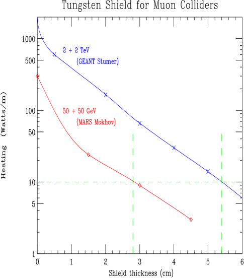
The magnet design is complicated by the fact that the ’s decay within the rings (), producing electrons whose mean energy is approximately that of the muons. With no shielding, the average power deposited per unit length would be about 2 kW/m in the 4 TeV machine, and 300 W/m in the 100 GeV Higgs factory. Fig. 10 shows the power penetrating tungsten shields of different thickness. One sees that 3 cm in the low energy case, or 6 cm at high energy would reduce the power to below 10 W/m which can reasonably be taken by superconducting magnets.
The quadrupoles could use warm iron poles placed as close to the beam as practical. The coils could then be either superconducting or warm, placed at a greater distance from the beam and shielded from it by the poles.
NEUTRINO RADIATION
Bruce Kingref41 has shown that the surface radiation dose in a time , in the plane of a bending magnet of field B(T), in a circular collider with beam energy , average bending field , at a depth (assuming a spherical earth), with muon current (of each sign) of is given by:
and that the dose at a location on the surface, in line with a high beta straight section of length is:
The first formula has been confirmed by a Monte Carlo simulation using the MARS codemokhovrad . In all cases it is assumed that the average divergence angles satisfy the condition: This condition is not satisfied in the straight sections approaching the IP, and these regions, despite their length, do not contribute a significant dose.
For the 3 TeV parameters given in Tb. 1 (muon currents and taking the federal limit on off site radiation Dose/year, to be 1 mSv/year (100 mrem/year), then the dose per year (defined as s), in the plane of a bending dipole is:
and for a straight section of length 0.6 m is:
which may be taken to be a reasonable limit.
Special care will be required in the lattice design to assure that no field free region longer than this is present. But it may be noted that the presence of a field of even 1 T over any length, is enough to reduce the dose to the 10 % Federal limit standard. For machines above 3 TeV, the muon current would probably have to be reduced.
For lower energy machines, the requirements get rapidly easier: a 0.5 TeV at 500 m depth could have 130 m straight sections, or if at 100 m depth 25 m lengths, for the same surface dose. For a 100 GeV machine the doses are negligible.
Detector Background
There will be backgrounds in the detector from the decay of muons in the ring and approaching the IP. A recent studyref39 of electromagnetic, hadronic and muon components of the background has been done using the GEANT codesref40 . This study
-
•
followed shower neutrons and photons down to keV and electrons to KeV.
-
•
Used a tungsten shield over the beam, extending in to within 14 cm of the intersection point, and extending outward to an angle of 20 degrees from the axis.
-
•
Inside this shield, between its smallest aperture 1 m from the IP, and its tip, the inner surface is shaped into a series of rising collimating steps and slopes, designed so that, the detector could not see any surface directly illuminated by the initial decay electrons, whether seen in the forward or backward (albedo) directions.
-
•
From the aperture point of minimum to a few meters (2.5 m for Higgs Factory) upstream, the inside forms another series of stepped collimators placed at (where is the rms divergence of the beam).
-
•
Further upstream, prior to the first quadrupole (from 2.5 to 4 m in the Higgs case) an 8 T dipole, with collimators inside, is used to sweep decay electrons before the final collimation.
Tb. 6 gives the hit density for the Higgs factory from the various sources and the occupancy of pixels of the given sizes. In all cases the numbers are given per bunch crossing. The hit density for the higher energy machines are found to be somewhat lower than these, due to the small decay angles of the electrons.
| Radius | cm | 5 | 10 | 20 | 100 |
|---|---|---|---|---|---|
| Photons hits | 26 | 6.6 | 1.6 | .06 | |
| Neutrons hits | 0.06 | 0.08 | 0.2 | 0.04 | |
| Charged hits | 8 | 1.2 | 0.2 | 0.01 | |
| Total hits | 34 | 8 | 2 | 0.12 | |
| Pixel size | 60x150 | 60x150 | 300x300 | 300x300 | |
| Occupancy all | % | 0.6 | 0.14 | 0.4 | 0.02 |
| Occupancy charged | % | 0.14 | 0.02 | 0.04 | 0.002 |
The radiation damage by the neutrons on a silicon detector has also been estimated. In the Higgs case, at 5 cm from the vertex, the number of hits from neutrons above 100 KeV is found to be per year (). This is an order of magnitude less than that expected at the LHC. The damages for silicon detectors in the higher energy machines are of the same order.
This study also found a significant flux of muons, with quite high energies, from pair production in electromagnetic showers (Bethe Heitler). Their most serious effect appears to arise when they make deeply inelastic interactions and deposit spikes of energy in the electromagnetic and hadronic calorimeters. This is not serious in the Higgs case, when the fluxes and cross sections are low, but at higher energies timing and/or longitudinal calorimeter segmentation appears necessary to identify and remove the problem.
CONCLUSION
Motive
-
•
Because they can be circular, muon colliders appear to be far smaller than hadron or machines of similar effective energy.
-
•
It is thus hoped that muon colliders could have a lower cost per TeV than other options.
-
•
Their smaller size would allow machines up to 3 TeV effective energy (roughly equivalent to a 30 TeV hadron machine) to fit on existing laboratory sites.
-
•
The low synchrotron and beamstrahlung radiation with muons could allow energy spreads as small as 0.003 % (3 x 10⁻⁵).
-
•
By measuring g-2 of the muon it should be possible to determine the energy to even greater precision.
-
•
The above, plus the large cross section for s-channel production, could make a muon collider into a precision tool to study Higgs particles and their decays.
Progress
-
•
The theory of operation of all components of a muon collider are now well understood.
-
•
Simulations of examples of all components of a baseline design have now been performed. The simulated performances of many of these components has exceeded the baseline specifications. All known effects have been included except space-charge in the cooling, whose effect, calculated analytically, appears not to be too large.
Needed
-
•
More detailed simulations of all components, including space-charge in the cooling.
-
•
Complete scenarios of the cooling stages and acceleration.
-
•
An experimental study of the target.
-
•
The construction and test of one or more of the cooling stages.
-
•
Technical development of components: a large high field solenoid for capture, low frequency rf linacs, multi-beam or pulsed magnets for acceleration, warm bore shielded high field dipoles for the collider, muon collimators and background shields, etc.. But none of these components can be described as exotic, and their specifications are not beyond what has been demonstrated.
ACKNOWLEDGMENTS
This research was supported by the U.S. Department of Energy under Contract No. DE-ACO2-76-CH00016 and DE-AC03-76SF00515.
References
- (1) V. V. Parkhomchuk and A. N. Skrinsky, Proc. 12th Int. Conf. on High Energy Accelerators, F. T. Cole and R. Donaldson, Eds., (1983) 485; A. N. Skrinsky and V.V. Parkhomchuk, Sov. J. of Nucl. Physics 12, (1981) 223; Early Concepts for Colliders and High Energy Storage Rings, Physics Potential & Development of Colliders. 2nd Workshop, Sausalito, CA, Ed. D. Cline, AIP Press, Woodbury, New York, (1995).
- (2) D. Neuffer, Fermilab Note FN-319, July 1979; Proc. 12th Int. Conf. on High Energy Physics (1983) 481; Principles and Applications of Muon Cooling, Part. Acc. 14 75 (1983)
- (3) Proceedings of the Mini-Workshop on Colliders: Particle Physics and Design, Napa CA, Nucl Inst. and Meth., A350 (1994) ; Proceedings of the Muon Collider Workshop, February 22, 1993, Los Alamos National Laboratory Report LA-UR-93-866 (1993) and Physics Potential & Development of Colliders 2nd Workshop, Sausalito, CA, Ed. D. Cline, AIP Press, Woodbury, New York, (1995); Proceedings of the 9th Advanced ICFA Beam Dynamics Workshop, Ed. J. C. Gallardo, AIP Press, Conference Proceedings 372 (1996).
- (4) R. B. Palmer et al., Monte Carlo Simulations of Muon Production, Physics Potential & Development of Colliders 2nd Workshop, Sausalito, CA, Ed. D. Cline, AIP Press, Woodbury, New York, pp. 108 (1995); R. B. Palmer, et al., Muon Collider Design, in Proceedings of the Symposium on Physics Potential & Development of Colliders, Nucl. Phys B (Proc. Suppl.) 51A (1996); R. B. Palmer and J. C. Gallardo, Muon-Muon and other High Energy Colliders, Techniques and Concepts of High Energy Physics IX, Phys. vol. 365, Ed. T. Ferbel, pp. 183, Plenum Pub. (1997).
- (5) R. B. Palmer and J. C. Gallardo, High Energy Colliders, Proceedings of 250th Anniversary Conference on Critical Problems in Physics, Princeton University, Ed. Fitch, Marlow, Dementi, pp. 247 (1997).
- (6) R. B. Palmer, Progress on Colliders , submitted to the Proceedings of the PAC97, Vancouver, Canada, June 1997.
- (7) Collider, A Feasibility Study, BNL-52503, FermiLab-Conf-96/092, LBNL-38946, Proceedings of the 1996 DPF/DPB Summer Study on High-Energy Physics, Snowmass’96. For updated information, see the Muon Collider Collaboration WEB page: http://www.cap.bnl.gov/mumu/.
- (8) R. Raja and A. Tollestrup, Calibrating the energy of a 50 x 50 GeV muon collider using spin precession, LANL preprint archive, hep-ex/9801004; submitted to Phys. Rev. D.
- (9) B. King, private communication
- (10) C. Ankenbrandt and B. Noble, Summary of the Accelerator Working Group, submitted to the Proceedings of Workshop on Physics at the First Muon Collider and at the Fron End, FNAL, Nov. 1997.
- (11) T. Roser, AGS Performance and Upgrades: A Possible Proton Driver for a Muon Collider, Proceedings of the 9th Advanced ICFA Beam Dynamics Workshop, Ed. J. C. Gallardo, AIP Press, Conference Proceedings 372 (1996).
- (12) C. Ankenbrandt, K-Y. Ng, J. Norem, M. Popovic, Z. Qian, L. Ahrens, M. Brennan, V. Mane, T. Roser, D. Trbojevic, W. van Asselt, Bunching Near Transition in the AGS, Fermilab Pub-98-006, submitted to Phys. Rev. D.
- (13) J. E. Griffin, K.Y. Ng, Z.B. Qian and D. Wildman, Experimental Study of Passive Compensation of Space Charge Potential Well Distortion at the Los Alamos National Laboratory Proton Storage Ring, Fermilab Report, FN-661, Nov. 1997.
- (14) C. Johnson, Solid and Liquid Targets Overview, presentation at the Mini-Wokshop: Target and Muon Collection Magnets and Accelerators, Oxford, MI, Jan. 1997.
- (15) C. Lu, K. T. McDonald, Low-Melting-Temperature Metals for possible Use as Primary Targets at a Muon Collider Source, Princeton//97-3, Revised Dec. 1997, unpublished.
- (16) R. Weggel, Deceleration of Conductor by Magnetic Field: 1) Paraxial; 2) Perpendicular, unpublished
- (17) M. Green and R. Palmer, A collider capture solenoid system for pions froma tilted target, submitted to the Proceedings of PAC97, May 1997.
- (18) N.V. Mokhov and A. Van Ginneken, Pion Production and Targetry at Colliders, Fermilab-Conf-98/041 (1998), submitted to Proc. of the 4th Int. Conf. on Physics Potential and Development at Colliders, San Francisco, CA, December 10-12, 1997
- (19) D. Kahana, et al., Proceedings of Heavy Ion Physics at the AGS-HIPAGS ’93, Ed. G. S. Stephans, S. G. Steadman and W. E. Kehoe (1993); D. Kahana and Y. Torun, Analysis of Pion Production Data from E-802 at 14.6 GeV/c using ARC, BNL Report # 61983 (1995).
- (20) N. V. Mokhov, The MARS Code System User’s Guide, version 13(95), Fermilab-FN-628 (1995).
- (21) J. Ranft, DPMJET Code System (1995).
- (22) Experiment E-910 at AGS, BNL, private communication.
- (23) N.V. Mokhov and S.I. Striganov, Towards Reliable Prediction of Particle Production for 6-120 GeV Proton Beams, presentation at the Workshop on Physics at the First Muon Collider and at the Front End of a Muon Collider, Nov. 1997.
- (24) J. R. Miller, M. Bird, S. Bole et al., An Overview of the 45 T Hybrid Magnet System for the National High Field Magnet Laboratory, IEEE Transactions on Magnetics 30, pp. 1563 (1994).
- (25) R. Weggel, 4-MW Hollow-Conductor Magnets for 20 T Hybrid Systems to Collect Pions for a Muon Collider, presentation at the Mini-Wokshop: Target and Muon Collection Magnets and Accelerators, Oxford, MI, Jan. 1997.
- (26) N. Mokhov, R. Noble and A. Van Ginneken, Target and Collection Optimization for Muon Colliders, Proceedings of the 9th Advanced ICFA Beam Dynamics Workshop, Ed. J. C. Gallardo, AIP Press, Conference Proceedings 372 (1996).
- (27) K. Assamagan, et al., Phys. Lett. B335, 231 (1994); E. P. Wigner, Ann. Math. 40, 194 (1939) and Rev. Mod. Phys., 29, 255 (1957).
- (28) B. Norum and R. Rossmanith, Polarized Beams in a Muon Collider, in Proceedings of the Symposium on Physics Potential & Development of Colliders, Nucl. Phys B (Proc. Suppl.) 51A (1996).
- (29) A. A. Mikhailichenko and M. S. Zolotorev, Phys. Rev. Lett. 71, (1993) 4146; M. S. Zolotorev and A. A. Zholents, SLAC-PUB-6476 (1994).
- (30) A. Hershcovitch, Brookhaven National Report AGS/AD/Tech. Note No. 413 (1995).
- (31) Z. Huang, P. Chen and R. Ruth, SLAC-PUB-6745, Proc. Workshop on Advanced Accelerator Concepts, Lake Geneva, WI , June (1994); P. Sandler, A. Bogacz and D. Cline, Muon Cooling and Acceleration Experiment Using Muon Sources at Triumf, Physics Potential & Development of Colliders 2nd Workshop, Sausalito, CA, Ed. D. Cline, AIP Press, Woodbury, New York, pp. 146 (1995).
- (32) Initial speculations on ionization cooling have been variously attributed to G. O’Neill and/or G. Budker see D. Neuffer in ref3 ; D. Neuffer, in Advanced Accelerator Concepts, AIP Conf. Proc. 156, 201 (1987); see also ref1 ; ref2 ; ref3 ; R. C. Fernow and J. C. Gallardo, Muon Transverse Ionization Cooling: Stochastic Approach, Phys. Rev. E52 1039 (1995).
- (33) R. Fernow, ICOOL, fortran program to simulate muon ionozation cooling.
- (34) P. Le Brun, Alternate solenoid in DPGeant, presented at the Mini-Workshop on Cooling, BNL Jan. 1998, unpublished.
- (35) H. Kirk, Parmela modeling of alternating solenoids presented at the Mini-Workshop on Cooling, BNL Jan. 1998, unpublished.
- (36) R. C. Fernow, J. C. Gallardo and R. B. Palmer, Ionization cooling using a FOFO lattice, BNL Report BNL #64493, submitted to PAC97, Vancouver, Canada, 1997.
- (37) Y. Zhao, The preliminary simulation of -mode interleaved side coupled standing wave structures, presented at the Mini-Workshop on Cooling, BNL Jan. 1998, unpublished.
- (38) A. Moretti, Rf Update, presented at the Mini-Workshop on Cooling, BNL Jan. 1998, unpublished.
- (39) D. Neuffer and A. Van Ginneken, Recent Cooling Simulation Studies, presented at the Mini-Workshop on Cooling, BNL Jan. 1998, unpublished.
- (40) V. Balbekov and A. Van Ginneken, Ring Cooler for Muon Collider, presented at the Mini-Workshop on Cooling, Fermilab Oct. 1997, unpublished.
- (41) D. Neuffer and W. Wan, COSY transport for cooling, presented at the Mini-Workshop on Cooling, Fermilab Oct. 1997, unpublished.
- (42) G. Silvestrov, Proceedings of the Muon Collider Workshop, February 22, 1993, Los Alamos National Laboratory Report LA-UR-93-866 (1993); B. Bayanov, J. Petrov, G. Silvestrov, J. MacLachlan, and G. Nicholls, Nucl. Inst. and Meth. 190, (1981) 9; C. D. Johnson, Hyperfine Interactions, 44 (1988) 21; M. D. Church and J. P. Marriner, Annu. Rev. Nucl. Sci. 43 (1993) 253.
- (43) G. Silvestrov, Lithium Lenses for Muon Colliders, Proceedings of the 9th Advanced ICFA Beam Dynamics Workshop, Ed. J. C. Gallardo, AIP Press, Conference Proceedings 372 (1996).
- (44) F. Mills and C. Johnstone, presentation at the 4th Int. Conference on Physics Potential and Development of Colliders, San Francisco, CA, Dec. 1997.
- (45) D. Summers, presentation at the 9th Advanced ICFA Beam Dynamics Workshop, Montauk 1995, unpublished.
- (46) G. Morgan, presentation at the 9th Advanced ICFA Beam Dynamics Workshop, Montauk 1995, unpublished.
- (47) D. Neuffer, Acceleration to Collisions for the Collider, Proceedings of the 9th Advanced ICFA Beam Dynamics Workshop, Ed. J. C. Gallardo, AIP Press, Conference Proceedings 372 (1996).
- (48) S.Y. Lee, K.-Y. Ng and D. Trbojevic, FNAL Report FN595 (1992); Phys. Rev. E48, (1993) 3040; D. Trbojevic, et al., Design of the Muon Collider Isochronous Storage Ring Lattice, Micro-Bunches Workshop, BNL Oct. (1995), AIP Press, Conference Proceedings 367 (1996).
- (49) K. L. Brown and J. Spencer, SLAC-PUB-2678 (1981) presented at the Particle Accelerator Conf., Washington, (1981) and K.L. Brown, SLAC-PUB-4811 (1988), Proc. Capri Workshop, June 1988 and J.J. Murray, K. L. Brown and T.H. Fieguth, Particle Accelerator Conf., Washington, 1987; Bruce Dunham and Olivier Napoly, FFADA, Final Focus. Automatic Design and Analysis, CERN Report CLIC Note 222, (1994); Olivier Napoly, it CLIC Final Focus System: Upgraded Version with Increased Bandwidth and Error Analysis, CERN Report CLIC Note 227, (1994).
- (50) A. Garren, C. Johnstone, Lattice Design for a 100 GeV Muon Collider, presentation at the 4th Int. Conference on Physics Potential and Development of Colliders, San Francisco, CA, Dec. 1997; A. Garren and C. Johnstone, Progress on a Lattice for a 2 TeV Muon Collider, submitted to the Proceedings of the PAC97, Vancouver, Canada, June 1997.
- (51) D. Trbojevic and K.-Y. Ng, submitted to Proc. of the 4th Int. Conf. on Physics Potential and Development at mu+mu- Colliders, San Francisco, CA, December 10-12, 1997
- (52) A. Drozhdin, C. Johnstone and N. Mokhov, Muon Collider Beam Collimation System, unpublished.
- (53) M. Furman, The Classical Beam-Beam Interaction for the Muon Collider: A First Look, BF-19/CBP-Note-169/LBL-38563, April 1996.
- (54) P. Chen, Beam-Beam interaction at Colliders, in Proceedings of the Symposium on Physics Potential & Development of Colliders, Nucl. Phys B (Proc. Suppl.) 51A (1996);
- (55) W.-H. Cheng, A. M. Sessler and J. Wurtele, Studies of Collective Instabilities in Muon Collider Rings, Proceedings of the 9th Advanced ICFA Beam Dynamics Workshop, Ed. J. C. Gallardo, AIP Press, Conference Proceedings 372 (1996).
- (56) A. Chao, Physics of Collective Beam Instabilities in High Energy Accelerators, John Wiley & Sons, Inc, New York (1993).
- (57) K.Y. Ng, Beam Stability Issues in a Quasi-Isochronous Muon Collider, Proceedings of the 9th Advanced ICFA Beam Dynamics Workshop, Ed. J. C. Gallardo, AIP Press, Conference Proceedings 372 (1996).
- (58) I. Stumer et al., Study of Detector Backgrounds in a Collider, Proceedings of the 1996 DPF/DPB Summer Study on High-Energy Physics, Snowmass’96.
- (59) Geant Manual, Cern Program Library V. 3.21, Geneva, Switzerland, 1993.
- (60) B. King, presentation at the Muon Collider Mini-Workshop: Lattice and Background, UCLA, Feb. 1997 and private communication.
- (61) N. V. Mokhov and A. Van Ginneken, Muon Collider Neutrino Radiation, presentation at the Muon Collider Collaboration Meeting, Orcas Is., Washington (1997); C.J. Johnstone and N.V. Mokhov, Shielding the Muon Collider Interaction Region, presented at the PAC97, Vancouver, Canada, 1997.
- (62) G. W. Foster and N. V. Mokhov, Backgrounds and Detector Performance at 2 + 2 TeV Collider, Physics Potential & Development of Colliders 2nd Workshop, Sausalito, CA, Ed. D. Cline, AIP Press, Woodbury, New York, pp. 178 (1995).