The ring imaging Čerenkov detector for the BRAHMS Experiment at RHIC
Abstract
A ring-imaging Čerenkov counter, to be read out by four 100-channel PMT’s, is a key element of the BRAHMS Experiment. We report here the most recent results obtained with a prototype tested at the BNL AGS using several radiator gases, including the heavy fluorocarbon C4F10 . Ring radii were measured for different particles for momenta ranging from 2 to 12 GeV/c employing pure C4F10 as radiator.
, , , ,
1 The BRAHMS Experiment
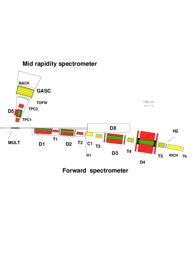
The BRAHMS Experiment at RHIC consists of two magnetic spectrometer arms that will survey particle production in Au - Au collisions at 100 GeV/c per nucleon. The goal of the experiment is to study the system formed by the two colliding ions in two regions of rapidity. A schematic description of the BRAHMS setup is shown in Figure 1. The Midrapidity Arm will probe the particles emerging near , corresponding to spectrometer angles between and with respect to the beam line. The Forward Arm will study particles of higher rapidities, , corresponding to spectrometer angles ranging from to .
The particle identification is accomplished in each spectrometer with a combination of Time of Flight arrays and Čerenkov counters. Of particular interest for this presentation is the Particle Identification system (PID) of the Forward Arm spectrometer, which must identify charged particles with momenta ranging from 1 to 25 GeV/c.
Particle identification at high momentum is done with the second Time of Flight wall H2 and the Ring Imaging Čerenkov detector RICH. Assuming the expected time resolution of psec, H2 will be able to separate pions from kaons up to 5.8 GeV/c. and kaons from protons up to 8.5 GeV/c. The function of the RICH detector is to extend the particle identification up to 25 GeV/c. Some considerations of its design are given in the following subsection.
2 Design of the RICH detector for BRAHMS
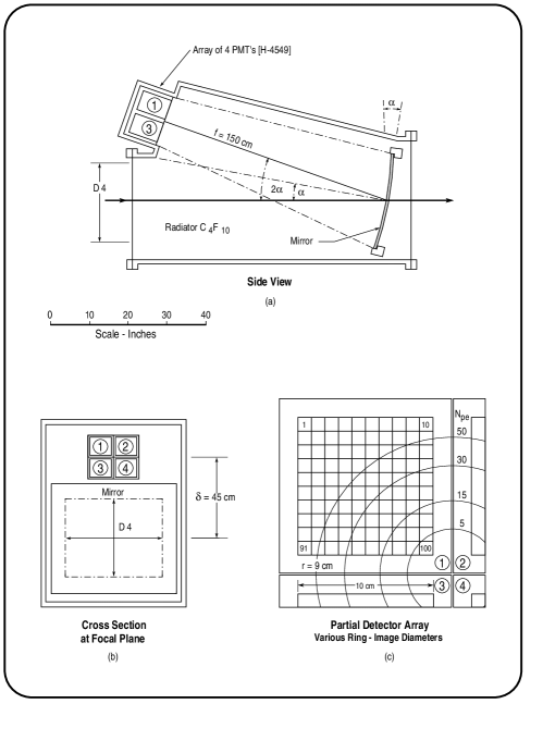
Figure 2 shows three aspects of the proposed detector, indicating various components and dimensions. The lateral dimensions of the radiator volume are somewhat larger than the aperture of D4 . The radiator has L = 1.5 meters of C4F10 , which at C and 1.25 atm. pressure has an index of refraction n = 1.00185. The spherical mirror has a focal length of 1.5 m and is rotated by an angle , thus shifting the ring image (by ) to a focal plane outside of the volume illuminated by the direct particle flux.
The photon-imaging array consists of four Hamamatsu R-4549-01 detectors, placed as indicated, defining an image plane some .
The expected performance of this detector, in terms of particle resolution and efficiency, have been outlined previously, [2],[3], and are supported by the results of the prototype tests presented in the following section and also in Ref. [1].
Simulations have been performed using event generators appropiate for Au-Au collisions, in order to determine the multiplicities expected for the various detectors of the Forward arm. Table 1 shows the pertinent data for the RICH detector, indicating typically one or at most two charged particles per event.
| Hits per event | Hits per event | |
|---|---|---|
| =7.5-15 GeV/c | =15-30 GeV/c | |
| Primary | 0.9 | 0.29 |
| Secondary | 0.5 | 0.39 |
| Above threshold | 0.8 | 0.30 |
3 The Prototype Detector
The prototype RICH counter is shown schematically in figure 3 of Ref. [1]. The prototype is similar in general design to that shown in figure 2, but with the optical system rotated by about the beam axis, such that the reflection angle is now in the horizontal plane.
The detector housing is constructed as a rectangular box, with 2 cm thick aluminum walls, having inner dimensions of 1276446 cm3 (). The construction is such that, using gasket and o-ring seals, the pressure of the radiator gas may be safely varied from 0 to 1.5 atm absolute. The particle beam enters and exits through Mylar windows 0.25 mm thick and 15 cm in diameter, at opposite ends of the long dimension. A 15-cm diameter spherical mirror, of focal length = 91.4 cm, is situated at a radiator distance of = 114 cm, rotated by = 8∘. A single 100-channel PMT is centered at at the 91 cm distant focal plane.
The photon detector was a single Hamamatsu R-4549-01, one element of the four proposed for BRAHMS. This PMT is a 20-stage device having a photocathode, with the segmentation defined by a array of anode elements. At the full operating voltage of 2500 Volts, it provides a current gain of producing single-photon pulses large enough to be fed directly to an ADC or timing electronics.
This specific module employs a special focussing electrode (between cathode and first dynode) which results in a rectangular flat-topped response function , with a very sharp fall off at the edges. While the photocathode itself is quite uniform, the gain falls off a bit (50%) near the edges of the array, and even more at the four corners. However the signal remains clean, and so the gain can be compensated in software.
Four identical drift chambers, placed in pairs upstream and dowstream of the prototype counter, provided tracking for determining the particle trajectory. Thus, the expected position of the center of each RICH ring on the phototube is determined to a resolution of approximately 500 m in both the and directions.
4 Measurements
In previous tests [1], time limitations did not permit a complete filling of the radiator volume with pure C4F10 . Our filling system was based on the difference (factor of six) in the molecular weights of the fluorocarbon and argon, with the heavy gas displacing the lighter one as it is brought into the bottom of the detector. In reality we found that even though the flow of C4F10 into the detector was slow, some mixing occurs and 100% concentrations cannot be reached in a single cycle. The measurements reported in our previous publication were done with C4F10 and Argon. This time we simply evacuated the radiator volume completely and then filled with pure C4F10 .
Measurements were made for several particle momenta, over the range , using the (negative) secondary beam from the BNL AGS accelerator. (The momentum calibration for the beam-line was established in a separate measurement, employing time-of-flight techniques, to an accuracy of better than 0.5%). For each setting, the tracking information from four drift chambers was used to project the expected ring centers onto the PMT matrix. Given this information, a ring-fitting algorithm was employed to find and fit the ring radius on an event by event basis. The results are shown in Fig. 3, which plots observed ring-radius versus beam momentum for particles thus identified as electrons, muons, and pions. The solid curves are calculated for the indicated particles, with the focal length and index of refraction as free parameters. Both results can be seen to agree well with the known value,, and the calculated index of refraction (at C, 1 atm nm) n = 1.001379 (this index is calculated using measurements in the liquid phase reported in [5]).
We have investigated the possibility that for larger rings (r4.5 cm) edge-effects may be of importance, resulting in extracted radii somewhat too small. For this purpose, the spherical mirror was further rotated by an additional 1∘ to =9∘. The projected ring center was therefore moved by 3.4 cm, such that one arc of the ring image was well inside the PMT’s photocathode area. The results for this comparison are shown in Fig. 3 for the electron data at 3 GeV/c. As can be seen, the effect produces, at most, a minimal displacement in the direction that might have been expected.
As remarked previously [1], the direct determination of the number of photons detected for a given event is precluded by the exponential shape of the PMT single-photon response function. Instead, we have measured (over a large number of events) the statistical variation in the total charge collected per event. The resultant distribution (Gaussian) is then fitted to determine the measured mean () and standard deviation (). The number of detected photons (n) may then be estimated as , where is deduced by unfolding the exponential detector response function. We thus estimated (for 12 GeV/c pions) that , corresponding to .
5 Summary
The predicted behavior of the RICH detector proposed for BRAHMS has been investigated and confirmed by these additional measurements with the prototype detector, which were carried out under carefully controlled conditions. The imaging capabilities (see Fig. 3) and figure of merit are found to be in good agreement with expectations based on the design and performance of the individual components.
References
- [1] R. Debbe, et al., Nucl. Instr. and Meth (in publication)
- [2] K. Ashktorab, et al., BRAHMS Conceptual Design Report, Brookhaven National Laboratory (October 1994).
- [3] R. Debbe, et al., “RD-44: Development of a RICH Detector for BRAHMS”, Internal BRAHMS Note #5 (1994).
- [4] Hamamatsu Corp., Bridgewater, NJ 08807.
- [5] T. Ypsilantis, Proc. of the Symposium on Particle Identification at High Luminosity Hadron Colliders, T. J. Gourlay and J. G. Mofin, ed. Fermilab, p. 133