Exciton-photon coupling in a ZnSe based microcavity fabricated using epitaxial liftoff
Abstract
We report the observation of strong exciton-photon coupling in a ZnSe based microcavity fabricated using epitaxial liftoff. Molecular beam epitaxial grown ZnSe/Zn0.9Cd0.1Se quantum wells with a one wavelength optical length at the exciton emission were transferred to a SiO2/Ta2O5 mirror with a reflectance of to form finesse matched microcavities. Analysis of our angle resolved transmission spectra reveals key features of the strong coupling regime: anticrossing with a normal mode splitting of at ; composite evolution of the lower and upper polaritons; and narrowing of the lower polariton linewidth near resonance. The heavy hole exciton oscillator strength per quantum well is also deduced to be .
Light-matter interaction inside quantum microcavities (MC) containing one or more quantum wells has seen growing interest since the first experimental observation of the normal mode splitting of the coupled oscillators.Weisbuch et al. (1992) The two coupled states, the lower and upper cavity-polaritons, are the result of the strong hybridization of the resonant cavity photon and quantum well exciton. The cavity-polariton lends itself to the possibility of a threshold-less laser,Imamoḡlu et al. (1996); Dang et al. (1998); Malpuech et al. (2002) ultrafast micro-optical amplifiers,Savvidis et al. (2000); Saba et al. (2001) and Bose-Einstein Condensation (BEC) in a solid state environment.Kasprzak et al. (2006)
Much of the work done in this area has focused on III-V MCsWeisbuch et al. (1992); Houdré et al. (1994); Savvidis et al. (2000); Saba et al. (2001) because of the high quality quantum wells and GaAs/AlAs distributed Bragg reflectors. However, the low binding energy of excitons found in typical III-V QWs () is not ideal. Saba et. al.Saba et al. (2001) show that the cut-off temperature for polariton parametric scattering, the proposed mechanism for a thresholdless laser, is determined by the exciton binding energy, and therefore room temperature operation is prohibited. Achieving BEC in MCs also requires sufficiently large binding energies such that the critical density can be reached before ionization. Wide bandgap II-VI based MCs are a promising alternative since the typical binding energy () is comparable to the room temperature thermal energy.Madelung (1996) Fabrication of II-VI MCs is a challenge with all growth techniques since suitable materials that satisfy the lattice matching criteria are in their infancy. To the best of our knowledge there are only a few demonstrations of II-VI based MCs, either involving growth-etch-growth processingKelkar et al. (1995); Pawlis et al. (2002) or the use of semiconductor mirrors.Dang et al. (1998); Feltin et al. (2006); Lohmeyer et al. (2006); Kasprzak et al. (2006) Large light penetration depth due to the low refractive index contrast and difficulties of strain management are inherent disadvantages of the latter approach.
We report here the successful fabrication and characterisation of ZnSe based MCs using a selective etching technique.Balocchi et al. (2005) This new technology has allowed us to fabricate high quality ZnSe based MCs with dielectric mirrors. The large binding energies found in ZnSe based QWs combined with the high performance of dielectric mirrors makes our samples ideally suited to the study of parametric scattering and BEC.
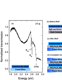
The active region of the cavity was grown by MBE on high quality GaAs substrates following deposition of a ZnSe buffer layer. A sacrificial layer of MgS () was grownBradford et al. (2001), then the active region, 5 ZnSe()/Zn0.9Cd0.1Se() quantum wells with ZnSe spacers () top and bottom such that the thickness of the active layer was equal to one optical wavelength at the emission of the well. Rotation of the sample was stopped during the growth of the top ZnSe spacer so as to allow translational tuning of of the completed MC. Small samples from the wafer were prepared by cleaving and coated with wax. The MgS sacrificial layer was selectively etched in a solution of HCl acid to free the active layer from the GaAs substrate. The lifted layer, supported by the layer of wax, was then transferred to a SiO2/Ta2O5 dielectric mirror. Details of the liftoff technique are reported elsewhere.Balocchi et al. (2005) Our mirrors are specifically designed such that the cavity linewidth, and electric field profile were optimum for strong coupling with our quantum wells.cou The mirror transmission was measured to be at with a structure designated by (, and ). Finally a second dielectric mirror was mechanically held against the active layer forming a MC of cavity length epi and refractive index . The completed MCs were transferred to a continuous flow cryostat and characterized at . All our fabrication steps were carried out in an air filtered environment, reducing the possibility of dust particles becoming trapped within the MC.
Reference samples were lifted and transferred to fused silica substrates and characterised by measuring their transmission at . White-light continuum generated with pulses from a Ti:Saphire laser was focused to a spot size of on the sample. The sample was normal to the optical axis. The transmitted light was collected with an angular resolution of at normal incidence by a multi-mode fibre bundle. The collected light was dispersed with a spectrometer with a resolution of and imaged onto a liquid nitrogen cooled CCD camera. Figure 1 shows the transmission of ZnSe/Zn0.9Cd0.1Se quantum wells lifted and transferred to a fused silica substrate. Two main optical features are the heavy-hole exciton and light-hole exciton transitions. A low energy oscillation is clear and is attributed to interference within the overall epitaxial layer. High energy features around correspond to bulk transitions in the ZnSe barriers.
The definitive experiment when searching for cavity-polaritons is the measurement of the optical angular dispersion. In the weak coupling regime the two states disperse independently. In the strong coupling regime the observed dispersion curves are distinctly altered on and near resonance, where they anticross with a normal mode splitting (Rabi splitting), typically a few .
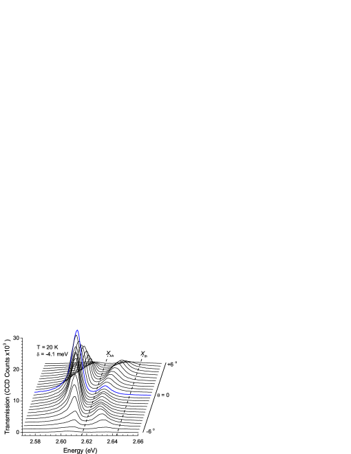
Completed microcavities were characterised by measuring white light transmission at . Two identical lenses, NA matched to the cryostat, were used to focus and collect light at the sample. Fully illuminating the objective lens, white light was focused at the sample and the transmitted light was collimated to a diameter of , where a fibred coupled spectrometer was used to scan through the collimated light and thus record a series of transmission spectra. In this way lateral displacement is related to angular dispersion inside the MC. Taking into account the glass substrate of the mirrors the range of angle at the MC surface was . Each spectrum was taken at different points through the centre of the collimated beam with increments of . Since the in-plane wavevector inside the cavity, is related to the angle of incident light by we can measure the dispersion curves of our samples in -space between . Figure 2 shows a series of spectra taken for one of our samples detuned to relative to the transition at normal incidence. The spectra are offset with the lowest spectrum corresponding to () increasing to (). The uncoupled and transition are indicated by the dotted lines. Two optical features clearly anticross on either side of the transition, the lower (LP) and upper polariton (UP), a clear demonstration of strong coupling.

Figure 3(a) shows the resonant transmission spectrum for the same detuning as figure 2. At this point on the dispersion curve, (), the composite states are in resonance and the energy separation between the two modes is a minimum. The peak energy values for the LP and UP are extracted from figure 2 and presented in figure 3(b) (open circles) as a function of . Treating the composite states of the polariton as coupled oscillators the eigenvalues of the coupling Hamiltonian were used to calculate the energy dispersion of the LP and UP taking the Rabi splitting, as fit parameter.Savona et al. (1995) The coupled and bare states are displayed as dotted and dashed lines respectively and give good agreement with the experimental data. The point of resonance is found to occur at with . The heavy hole exciton oscillator strength, can be determined from the expression,Savona et al. (1995) , where the number of quantum wells, , the cavity refractive index, and effective cavity length, are , and respectively. is the free electron mass. For our microcavity we deduce an oscillator strength per quantum well, . This is similiar to for MCs studied by Kelkar et. al..Kelkar et al. (1995)
The polariton state transmission amplitude is a measure of the polariton composite ratio.Hopfield (1958) In Figure 3(c) we present the normalized integrated intensities, of the LP and UP branch giving a proportional indication of the evolution of the photonic fraction of the polariton. We have defined such that . In the angular range of the LP is predominantly photon-like, indicated by the increase in the LP intensity. Beyond this range the LP weakens as it becomes progressively more excitonic and . The UP behaves inversely. We also note that on resonance, figure 3(a), . holds at larger beyond resonance. This is also the case in the MC studied by Kelkar et. al..Kelkar et al. (1995) The measured linewidths, of the LP and UP are presented in figure 3 (d). Narrowing of the LP linewidth is clearly evident and occurs at ().Kavokin (1998) This is evidence that the extended nature of the polariton averages out some of the inhomogeneous broadening in the quantum well exciton.
In conclusion, we have shown that high quality ZnSe based MCs can be fabricated with the use of an epitaxial liftoff technique.Balocchi et al. (2005) We have successfully demonstrated three key features of the strong coupling regime: anticrossing of the cavity polariton with a normal mode splitting of ; composite fractional evolution of the LP and UP; and narrowing of the LP linewidth near resonance. We also deduce the heavy hole exciton oscillator strength to be . Our fabrication technique has eliminated the need for complicated growth-etch-growth processing whilst still employing the advantages of large exciton binding energies found in wide bandgap II-VI materials and high reflectivity offered by dielectric mirrors. Additionally, the epitaxial liftoff technology can potentially be developed to fabricate MCs with MgS/ZnSe quantum wells with an even higher exciton binding energies, .Urbaszek et al. (2000) The combination of prolonged photonic lifetimes, due to the achievable high finesse, and the large excitonic oscillator strength are ideally suited to nonlinear phenomena such as parametric scattering and BEC.
This work was funded by EPSRC, UK.
References
- Weisbuch et al. (1992) C. Weisbuch, M. Nishioka, A. Ishikawa, and Y. Arakawa, Phys. Rev. Lett. 69, 3314 (1992).
- Imamoḡlu et al. (1996) A. Imamoḡlu, R. J. Ram, S. Pau, and Y. Yamamoto, Phys. Rev. A 53, 4250 (1996).
- Dang et al. (1998) L. S. Dang, D. Heger, R. André, F. Bœuf, and R. Romestain, Phys. Rev. Lett. 81, 3920 (1998).
- Malpuech et al. (2002) G. Malpuech, A. D. Carlo, A. Kavokin, J. J. Baumberg, M. Zamfirescu, and P. Lugli, Appl. Phys. Lett. 81, 412 (2002).
- Savvidis et al. (2000) P. G. Savvidis, J. J. Baumberg, R. M. Stevenson, M. S. Skolnick, D. M. Whittaker, and J. S. Roberts, Phys. Rev. Lett. 84, 1547 (2000).
- Saba et al. (2001) M. Saba, C. Ciuti, J. Bloch, V. Thierry-Mieg, R. Andre, L. S. Dang, S. Kundermann, A. Mura, G. Bongiovanni, J. L. Staehli, and B. Deveaud, Nature 414, 731 (2001).
- Kasprzak et al. (2006) J. Kasprzak, M. Richard, S. Kundermann, A. Baas, P. Jeambrun, J. M. J. Keeling, F. M.Marchetti, M. H. Szymanska, R. Andre, J. L. Staehli, et al., Nature 443, 409 (2006).
- Houdré et al. (1994) R. Houdré, C. Weisbuch, R. P. Stanley, U. Oesterle, P. Pellandini, and M. Ilegems, Phys. Rev. Lett. 73, 2043 (1994).
- Madelung (1996) O. Madelung, ed., Semiconductors - Basic Data (Springer, 1996), 2nd ed.
- Kelkar et al. (1995) P. Kelkar, V. Kozlov, H. Jeon, A. V. Nurmikko, C. C. Chu, D. C. Grillo, J. Han, C. G. Hua, and R. L. Gunshor, Phys. Rev. B 52, R5491 (1995).
- Pawlis et al. (2002) A. Pawlis, A. Khartchenko, O. Husberg, D. J. As, K. Lischka, and D. Schikora, Solid State Comm. 123, 235 (2002).
- Feltin et al. (2006) E. Feltin, G. Christmann, R. Butté, J. Carlin, M. Mosca, and N. Grandjean, Appl. Phys. Lett. 89, 071107 (2006).
- Lohmeyer et al. (2006) H. Lohmeyer, K. Sebald, C. Kruse, R. Kröger, J. Gutowski, D. Hommel, J. Wiersig, N. Baer, and F. Jahnke, Appl. Phys. Lett. 88, 51101 (2006).
- Balocchi et al. (2005) A. Balocchi, A. Curran, T. C. M. Graham, C. Bradford, K. A. Prior, and R. J. Warburton, Appl. Phys. Lett. 86, 011916 (2005).
- Bradford et al. (2001) C. Bradford, C. B. O’Donnell, B. Urbaszek, A. Balocchi, C. Morhain, K. A. Prior, and B. C. Cavenett, J. Cryst. Growth 227, 634 (2001).
- (16) The bare exciton linewidth, was matched to satisfying, . The stacking order of the layers was such that the antinode of the electric field inside the cavity was positioned at the quantum wells.
- (17) The epitaxial layer thickness deduced from figure 1 was used in the coupled oscillator model in figure 3(b).
- Savona et al. (1995) V. Savona, L. C. Andreani, P. Schwendimann, and A. Quattropani, Solid State Comm. 93, 733 (1995).
- Hopfield (1958) J. J. Hopfield, Phys. Rev. 112, 1555 (1958).
- Kavokin (1998) A. V. Kavokin, Phys. Rev. B 57, 3757 (1998).
- Urbaszek et al. (2000) B. Urbaszek, A. Balocchi, C. Bradford, C. Morhain, C. B. O’Donnell, K. A. Prior, and B. C. Cavenett, Appl. Phys. Lett. 77, 3755 (2000).