Sub-lambda gratings, surface plasmons, hotter electrons and brighter x-ray sources- enhanced absorption of intense, ultrashort laser light by tiny surface modulations
Abstract
We observe near 100 absorption of light in intense ultrashort laser plasma interaction in a metal coated (Au on glass) sub- grating structure under suitable conditions and the subsequent ’hot’ electron generation from the grating plasma. In the low intensity regime we determine the conditions in which a monochromatic infrared light ( = 800nm corresponding to the central wavelength of the ultrashort laser that we used in subsequent experiments) efficiently excites surface plasmon in the grating. Then we study how the surface plasmon resonance condition changes when we excite them using low intensity ultrashort pulses. We look at the reflectivity of light varying the incident light intensity over a wide range (-). The reflectivity of grating with the resonance condition satisfied is the lowest over the whole range of intensity. We compare the data with those obtained from highly polished ( /10) Au mirror target under identical conditions. At high intensities we look at the hard x-ray emission from both the targets with and without the resonance condition. The hard X-ray spectrum shows a bimaxwellian i.e two temperature hot electron distribution with a hotter component present under the resonance condition while in all other cases it shows the presence of only one low temperature component.
pacs:
52.25.Nr, 52.40.Nk, 52.50.Jm, 42.65.ReThe interaction of intense, ultrashort laser pulses with optically flat solid surfaces result in hot solid density plasmas. The exotic state of hot, dense matter, thus created, is hydrodynamically frozen in the time scale of the parent ultrashort (subpicosecond) pulse rendering the plasma highly inhomogeneous. These dense laser produced plasmas are sources of hot suprathermal electrons and their signature bremsstrahlung hard x-ray radiation. Understanding the generation of these hot electron pulses and their transport through matter under extreme conditions together, pose a difficult problem in itself which is of utmost importance from the point of view of the proposed Fast Ignition scheme Tabak which holds the potential of realising laser fusion. On the other hand, femtosecond x-ray pulse emission has recently made it possible to monitor ultrafast motions in nature Siders ; Petruck . Thus the need to explore novel ways to optimize the hot electron generation as well as finding ways to control it cannot be overemphasized. Ideally one would like to couple all the incident light to the plasma, which generally is not very keen on light absorption, and maximise the temperature and number of hot electrons and consequently the hard x-ray emission. In deuterium cluster gas jet almost 90 absorption of laser energy has been reported Ditmire . In solids attempts on enhancing the continuum emission by structuring the target surfaces are also reported. For example, recent literature reports impressive enhancements in soft Murnane and moderately hard x-ray regions Wulker using structured surfaces, viz. gratings Murnane ; Gauthier ; Gordon , “velvet” coatings Kulcsar , porous and nanocylinder Gordon ; Nishikawa ; Nishikawa2 targets. We have recently observed that irradiating metal nanoparticles on a surface tremendously enhances the hard x-ray bremsstrahlung from these plasmas Rajeev . Plasmas with varied scale-lengths are known to yield significant enhancements at the cost of an increase in the x-ray pulse duration Nakano ; Bastiani .
In this letter we report the highest absorption of incident laser light on solid density plasma till date. Using a simplistic one dimensional periodic system we experimentally pinpoint the window where incident light is almost completely absorbed resulting in very hot electrons at moderately low light intensity. We believe this is the first systematic study of reflectivity of high intensity light from sub- gratings.
One of the intuitive ways to couple more light would be to restrict light by some mechanism to localized regions on the target, i.e to trap the incident electromagnetic radiation on the target. Surface-bound electromagnetic charge density waves on metals, so called surface plasmon polaritons (SPs), which when excited lead to such localization. It needs a metal (, ) dielectric (, ) interface to excite a SP which is a propagating solution of Maxwell equations that exponentially decays in both directions away from the interface. The SP dispersion curve, as is well known lies to the right of the light-line and thus for the SP to interact with the incident EM radiation it needs a supply of additional momentum. In our experiments we use a one dimensional periodic sub- gold grating to satisfy the momentum matching condition. In case of a sinusoidal grating of period d and amplitude (groove depth) small enough not to perturb the SP dispersion relation we can write, , where is the wave vector of light incident at an angle . We look at reflectivity of light from the sub- grating under conditions that all the diffraction orders apart from the specularly reflected one are quenched.
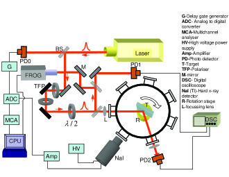
The experiments are performed using a Ti: Sapphire chirped pulse amplified laser (Thales Laser, Alpha 10) emitting 55 fs pulses centered at 800 nm wavelength at 10 Hz repetition rate. The laser pulses have a contrast of 106 in picosecond timescales and under optimum extraction, the prepulse (12 ns before the main pulse) intensity level is less than 10-6 of the main pulse. The prepulse or the pedestal do not cause significant plasma formation under our experimental conditions. The laser is focussed at oblique incidence with a f/20 lens on targets housed in a vacuum chamber at 10-4 torr. The target movement is controlled The maximum pulse energy used in the present set of experiments, give a peak intensity of about 3 1015 Wcm2 at a 60 m focal spot. The beam is intentionally focussed loosely so as to have a precisely defined angle of incidence by minimising beam divergence. A thin half wave plate in the beam path selects the polarization state of light field. The intensity of incident light is controlled by using high contrast thin film polarizer and half wave plate combinations. The experiments involving very low intensity laser pulses are performed using unamplified nJ, 55fs modelocked pulse train (74 MHz) delivered by a Ti:sapphire oscillator. The target is constantly translated in the focal plane in order to avoid multiple laser hits at the same spot. In the series of low intensity experiments () with continuous laser or oscillator pulse train the reflected light is collected using a calibrated power meter (Gentec). For measuring reflectivity as a function of intensity, the reflected signal is collected using integrating spheres and calibrated photodiodes. The hard x-ray bremsstrahlung ( 25 keV - 250 KeV) emission under high intensity laser irradiation is measured using a properly calibrated NaI(Tl) scintillating detector looking along the plasma plume (i.e. normally into the target). The data acquisition is time gated, where the 30 s collection time window is opened in synchronization with the incident laser pulse. The hard x-ray count rate is kept below one per second, i.e. 0.1 per laser shot by adjusting the solid angle subtended into the detector in order to avoid pile up problem in the detector.
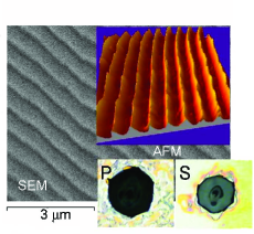
In our experiments we used two types of targets. We used triangular blazed gratings (period, d = 555 nm; groove depth, h = 158nm, blaze angle 17.450) with gold coating on glass substrate and compared all the data against polished (roughness /10) gold coated glass targets.
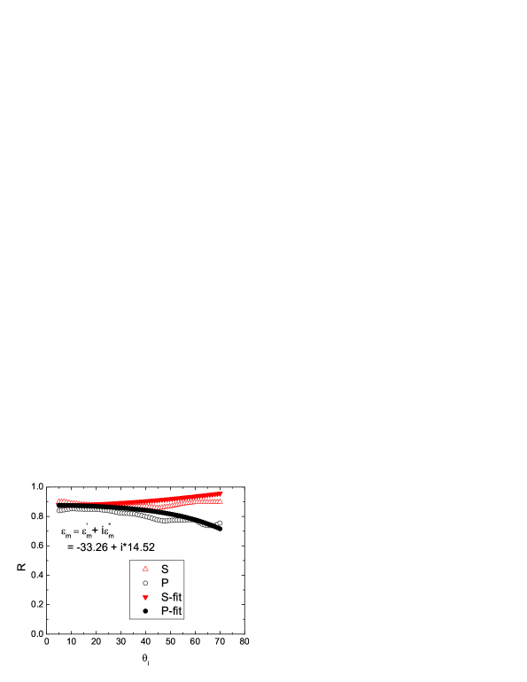
The thickness of gold layer in both the cases is many times greater than the optical skin depth, = 0.218 nm in our case ( = 800 nm). Consequently, in all our experiments the glass background does not have any significant role to play and the flat mirror as well as the sub- grating structure can be effectively assumed to be made of gold only. The dielectric constant for Au () at = 800 nm is extracted from the s and p reflectivity vs. angle of incidence data (a typical one is shown in Fig.2) by using Fresnel reflectivity formulae for an absorptive medium with a complex refractive index BornWolf . For Au metal vacuum interface we find, = -33.26 + i14.52 which is reasonably close to the values found in literature OSA . The Drude model prediction, = -32.81 matches reasonably with the value we obtain experimentally implying that at = 800 nm there is no interband absorption in metallic Au. In our experiments we kept the grating wave vector aligned in the plane of incidence of light. A sub- ( 1) grating permits only two diffraction
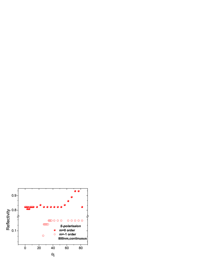
orders, i.e. the specularly reflected one m = 0 and the m = -1th order Gauthier . Fig.3 and Fig.4 shows the fraction of incident energy diffracted by the grating into the two available orders for s and p polarisations respectively as a function of the angle of incidence. In the experiments with low intensity CW light we note that for both the polarisations the sub- structure starts diffracting the -1th order above a certain angle = 23, below which we only have specularly reflected light, i.e. below the grating ceases to be a diffracting medium and acts like a mirror whose reflectivity is polarisation independent. For s polarisation, light is mainly specularly reflected and the reflectivity does not change with angle of incidence. In contrast, the p polarised light shows a sharp dip (solid circles in Fig.4) in specular reflectivity with the minimum at an angle which is same as . At this angle almost all the light () that is incident is completely absorbed. For p polarisation is the angle at which the phase matching condition is satisfied and it corresponds to a situation where the incident electromagnetic radiation efficiently communicates with the surface charge density oscillations leading to very strong excitation of surface plasmon, i.e. a condition known as surface plasmon resonance(SPR). For continuous light, the delta function like spectrum implies a very strict resonance condition (phase matching condition) which manifests itself as a very sharp dip in reflectivity around (Fig.4: solid circles). In the case of ultrashort pulse light ( 55 fs), the spectrum being broad ( 50 nm bandwidth in our case) the resonance condition is far more relaxed, and we observe a broader SPR dip (Fig.4: crossed circles). The peak absorption is also lower () here owing to the fact that at SPR only the central wavelength of the spectrum excites SP. The phase matching condition for a low amplitude sinusoidal Au grating
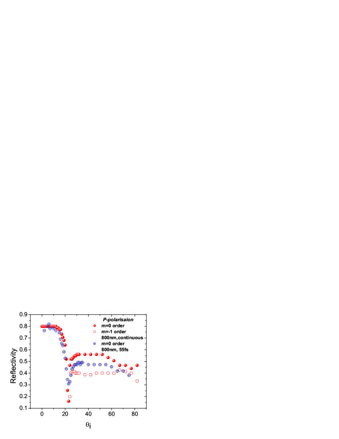
and vacuum interface is, , where , and b=. With = -33.26 + i14.52, d = 555 nm and = 800 nm the SPR angle comes out to be = which is a close match to the experimentally observed angle considering the fact that we have used triangular gratings for our experiments. Fig.2 shows the SEM and AFM image of the grating. We looked at the reflectivity of p and s polarised light from both structued and polished flat metallic surfaces at this particular angle of incidence (), while varying the intensity of incident light over three orders of magnitude (see Fig.5 and Fig.6). Flat Au mirror reproduces the metallic reflectivity as measured in Fig2. for the same angle of incidence and does so till the intensity reaches
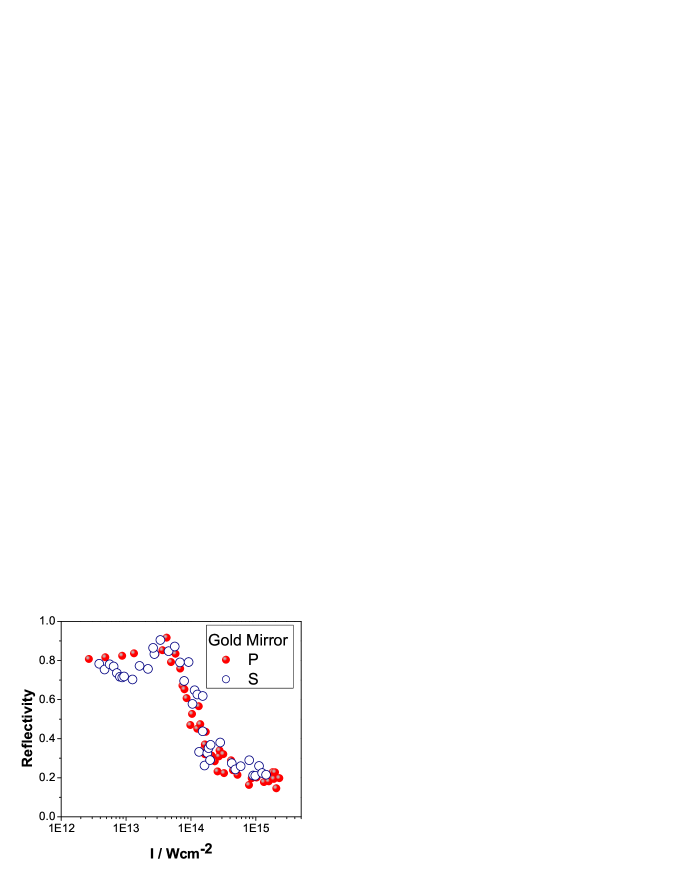
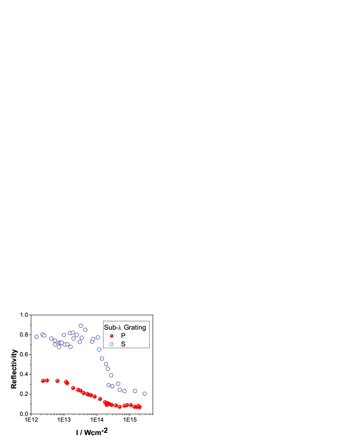
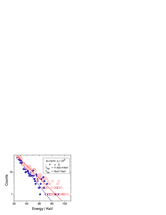
which is the plasma formation threshold for the material. Beyond this value plasma is formed at the leading edge of the laser pulse and rest of the light is reflected from the gold plasma which reflects less than the gold metal. Under our experimental conditions the scale length, of the plasma is very small and the p polarised light incident at a small angle of does not create conditions favourable to resonance absorption (RA) which excites the longitudinal electrostatic charge density oscillations across the density gradient in the highly inhomogeneous plasma Kruer created by the ultrashort pulse. Fig.5 shows that s and p reflectivity are the same within the error bars of the experiment and corroborates this fact. As shown in Fig.6 we observe that the grating reflectivity (Note that only one diffraction order for this particular angle of incidence) for s polarisation shows exactly the same behaviour as optically flat Au with the same threshold for plasma formation in it. The reflectivity of p polarised light from grating shows interesting behaviour. At low intensity it starts from the value 0.33 which, as expected, is roughly the same as the reflectivity of ultrashort pulse assisting SPR as shown in Fig.4. The plasma formation threshold in this case is dramatically reduced by a factor of 3 to a value . Assuming that the metallic sub- structures under light irradiation, at least till the moment plasma is formed, act as localized pockets of enhanced electric fields, we expect f to remain the same for both the grating (G) as well as the mirror (M), i.e , where f is the absorption (1-R), R being the reflectivity and is the threshold of plasma formation. In the case of p polarised light, =0.67, =0.17 and = which implies that, = matching quite nicely with the experimentally observed value. The absorption increases with increasing intensity and at about reflectivity drops by 4.7 times its low intensity value and almost 93 of the incident light is absorbed. The absorbed light goes into the plasma and ultimately manifests itself, among other things, as hot electrons. These hot electrons leave the expanding plasma both towards the vacuum side giving rise to ion acceleration due to capacitive effects, and also towards the higher density solid region suffering collisions with the charge centers and in the process emitting incoherent bremsstrahlung hard x-ray and characteristic line radiations. The bremsstrahlung photon energy distribution carries information about the hot electron temperature and the bremsstrahlung yield correspond to the number of hot electrons. Fig.7 shows the hard x-ray spectrum obtained from high intensity (I = 3.8) laser produced plasma on flat gold-coated glass target and it shows the presence of only one temperature hot electrons, though p-polarisation ( KeV) produces hotter electrons compared to s-polarisation ( KeV).
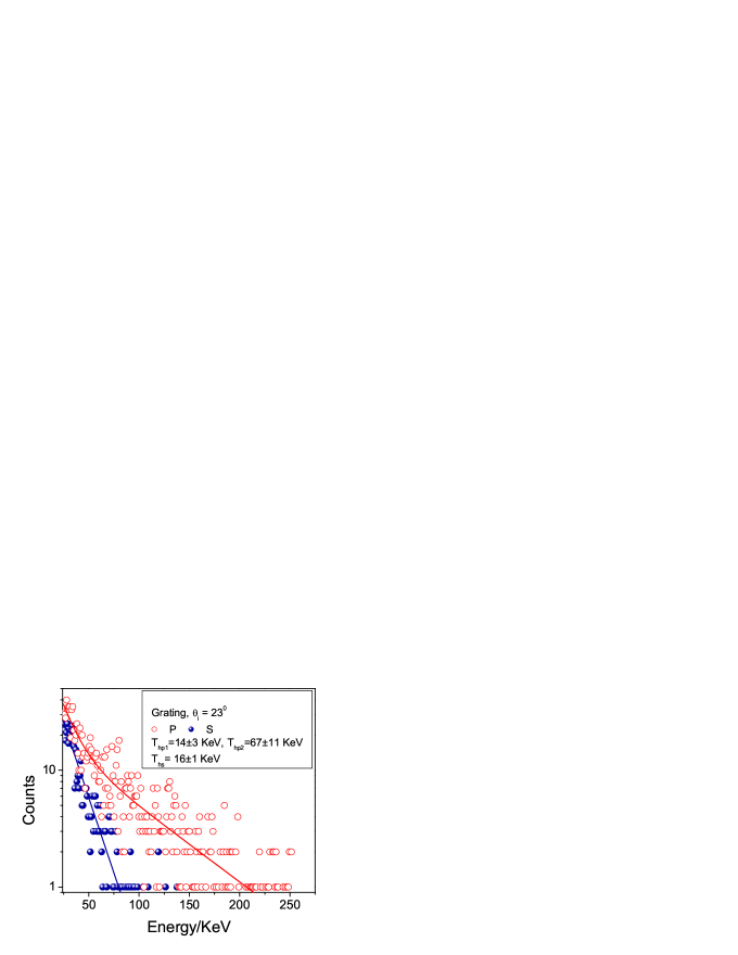
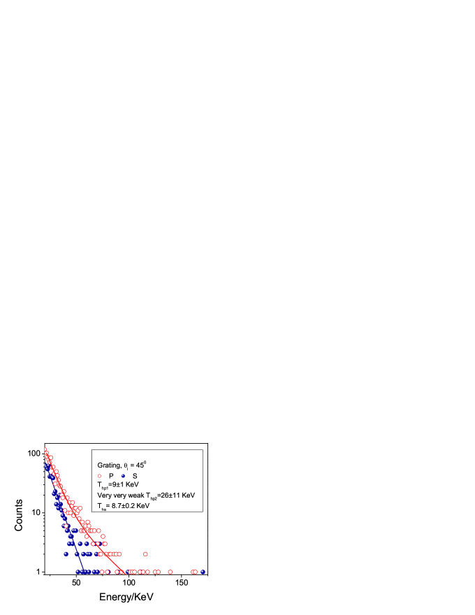
The lower half of Fig.7 shows hard x-ray emission spectrum from the plasma generated on the grating surface when it is allowed to interact with intense (I = 3.8) laser incident at the SP resonance angle. s-polarisation gives rise to maxwellian hot electron distribution with single temperature component around KeV while for p-polarisation the spectrum is shows non-maxwellian behaviour with two temperature hot electron distribution: one at KeV and the other at KeV the higher component constituting 14 of the total number of hot electrons. The hard x-ray yield for p-polarised light is 4.8 times that of s-polarised case. That, the surface plasmon coupling plays the most crucial role here (in the case of gratings) in the enhanced generation of hotter electrons, is verified when we observe grating-plasma hard x-ray spectrum ( at the same I = 3.8 )at an angle of incidence that does not excite surface plasmon modes, i.e. at an angle where the reflectivity dip is not there. The Fig.9 shows one such spectrum at . Here, s-polarisation produces one temperature electron distribution at KeV. p-polarisation gives rise to mainly (99 weightage) one hot electron temperature at KeV and a very feeble high temperature component around KeV.
Thus we see that the surface plasmons that are efficiently excited at resonance in the low intensity region maximise light absorption in the structured metallic surface. In the low intensity regime the excited nonradiative SPs relax by dumping their energy to the background lattice and thus heating up the lattice. In our experiments we see that it is possible to enhance to a great extent the light coupling in the high intensity regime by exploiting SPR. The very short length scale plasma retains the imprint of grating structure in it’s profile during its interaction with the incident pulse. The reflectivity curves show that the high level of light absorption is maintained even when we increase the light intensity over 3 orders of magnitudes. The lowering of the threshold of plasma formation in grating targets under conditions favourable to SPR is indicative of the increase in the effective field intensity due to the surface plasmon assisted local field enhancement. Fig.2 inset shows the high magnification optical microscopic image of the focal spot at the sample after irradiation of the grating surface with high intensity laser while maintaining the SPR angle, under two polarisation conditions. In both the cases the magnification is kept the same. Note that the pit formed due to p-polarisation (SPR) is bigger and deeper compared to that due to s-polarisation (No SPR) as expected from the reflectivity data. The grating surface surrounding the focal spot is also much more damaged in p irradiated spot, a feature that indicates violent excitation of surface charge density oscillations when the grating is exposed to incoming high intensity ultrashort laser pulse and larger length of propagation of the generated SP wave along the metal vacuum interface.
In short, we have studied the reflectivity of incident light from a 1-d sub- periodic gold structure as a function of light intensity, over three orders of magnitude, at an angle of incidence that maintains SPR at low intensity. The light absorption is compared to that of a flat Au target. We see almost complete absorption of light. From the bremsstrahlung radiation at high intensity we observe that SPR is assisting the generation of hotter electrons in larger numbers. One can tune the hot electron temperature by switching the polarisation state of the light under SPR. We believe that this study is the first direct evidence that SPs do couple the incident light and transfer the energy to the plasma even at high intensities.
References
- (1) M. Tabak, J. M. Hammer, M. E. Glinsky, W. L. Kruer, S. C. Wilks, and J. Woodworth, Phys. Plasmas , 1626 (1994)
- (2) C.W. Siders et al., Science , 1340 (1999), A. Cavalleri et al., Phys. Rev. Lett. , 237401-1 (2001).
- (3) C. Rose-Petruck, R. Jimnenez, T. Guo, A. Cavalleri, C. W. Siders, F. Raksi, J. A. Squier, B. C. Walker, K. R. Wilson, C. P. J. Barty, Nature , 310 (1999).
- (4) T. Ditmire, J. Zweiback, V. P. Yanovsky, T. E. Cowan, G. Hays and K. B. Wharton Nature , 489-492 (1999)
- (5) M.M. Murnane et al., Appl. Phys.Lett. , 1068 (1993).
- (6) C.. Wulker et al., Appl. Phys. Lett. 1338 (1996).
- (7) J.C. Gauthier et al., Proc. SPIE , 242 (1995).
- (8) William L. Kruer, The Physics of Laser Plasma Interactions (Addition-Wesley Publishing Company).
- (9) S. P. Gordon et al., Opt. Lett. , 484 (1994).
- (10) G. Kulsar et al., Phys. Rev. Lett. , 5149 (2000).
- (11) T.Nishikawa et al., Appl Phys.Lett. , 1653 (1997).
- (12) T. Nishikawa et al., Appl. Phys. B , 185 (2001).
- (13) P. P. Rajeev, P. Taneja, P. Ayyub, A. S. Sandhu, and G. R. Kumar, Phys. Rev. Lett. , 115002 (2003).
- (14) H. Nakano, T. Nishikawa, and N. Uesugi, Appl Phys.Lett. , 24 (2001).
- (15) S. Bastiani, A. Rousse, J. P. Geindre, P. Audebert, C. Quoix, G. Hamoniaux, A. Antonetti, and J. -C. Gauthier, Phys. Rev. E , 7170 (1997).
- (16) M. Born and E. Wolf, Principles of Optics: Electromagnetic Theory of Propagation, Interference and Diffraction of Light (Cambridge University Press, Edition).
- (17) Handbook of Optics (Optical Society of America, Edition).
- (18) Ch. Reich, P. Gibbon, I. Uschmann, and E. Forster, Phys. Rev. Lett. , 4846 (1995).
- (19) G. Malka, N. Blanchot, D. Desenne, M. L. Jacquet, A. Mens, J. L. Miquel, and O. Peyrusse, J. Opt. Soc. Am. B , 2091 (1997).
- (20) M. Yoshida, Y. Fujimoto, Y. Hironaka, K. G. Nakamura, K. Kondo, M. Ohtani, and H. Tsunemi, Appl Phys.Lett. , 2393 (1998).
- (21) Ch. Ziener, I. Uschmann, G. Stobrawa, Ch. Reich, P. Gibbon, T. Feurer, A. Morak, S. Dusterer, H. Schworer, E. Forster, and R. Sauerbrey, Phys. Rev. E, , 066411-1 (2002).
- (22) D. Salzmann, Ch. Reich, I. Uschmann, E. Forster, and P. Gibbon, Phys. Rev. E , 036402 (2002).
- (23) D. C. Eder, G. Pretzler, E. Fill, K. Eidmann, and A. Saemann, Appl. Phys. B 211 (2000).
- (24) P. P. Rajeev and G. Ravindra Kumar, Optics Communications
- (25) P. Ayyub et al., Appl. Phys. A , 67 (2001).