A Pair Polarimeter for Linearly Polarized High Energy Photons
Abstract
A high quality beam of linearly polarized photons of several GeV will become available with the coherent bremsstrahlung technique at JLab. We have developed a polarimeter which requires about two meters of the beam line, has an analyzing power of 20% and an efficiency of 0.02%. The layout and first results of a polarimeter test on the laser back-scattering photon beam at SPring-8/LEPS are presented.
pacs:
07.60.F polarimeters, 29.40.Wk solid state detectorsI Introduction
Electron-positron pair photo-production from amorphous matter can be calculated exactly in the framework of QED Max59 . The azimuthal distribution in this reaction can be presented as , where is degree of photon linear polarization, the analyzing power of the process and the azimuthal angle between the polarization plane and the detected particle(s). The value of ranges from 0.1 to 0.3 depending on the reaction kinematics. The use of the reaction in polarimetry was suggested in 1950 You50 . The main experimental challenge in such a polarimeter is the small angle between the pair components. This was resolved by using a magnetic field to separate the electron and positron Bar62 at the price of a reduced analyzing power. For photons in the few GeV energy range a different solution was proposed Woj98 based on a silicon microstrip detector, of which the unique high track resolution allows the observation a pair with a separation as small as 100 m.
II Kinematics
Figure 1 illustrates the kinematics of electron-positron pair production and its relevant variables. The use of the angle , which is the azimuthal angle of the plane, yields a value of for the case of a very thin converter and equal energies of the electron and positron.
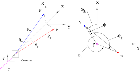
In the determination of the asymmetry we used a vector constructed from the momenta of the electron(), the positron(), and the photon() as
where , . This vector lies in the plane perpendicular to the photon momentum k. The direction of the nω vector is determind from the positron and the electron tracks in the detector, even the position of the pair creation vertex is not detected.
From the azimuthal dependence of asymmetry we find :
| (1) |
where is the number of pairs observed at the angle for the photon polarization e parallel to the vertical and is the number of pairs observed at the angle for the horizontal photon polarization, is the tilt of the detector axis.
III Experiment
III.1 Layout
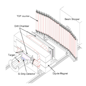
The experiment was performed at the SPring-8 facility in Japan. SPring-8 is a third-generation synchrotron radiation facility with 62 beam lines for various applications. One of the beam lines with high-energy photons is used for high-energy nuclear physics. The photons are produced by backward Compton scattering laser light off the electrons circulating in the storage ring. The beam line is called LEPS (Laser Electron Photon beam line at SPring-8) Nak01 . The laser system focuses the light at the intersection region located between two bending magnets in the storage ring. An Argon laser provides the laser beam with a wave length of 351 nm for which the maximum energy of the produced photons is 2.4 GeV. The tagging system employs the bending magnet located down stream of the interaction region for analyzing the momentum of the electrons. The energy resolution of the tagging system is about 15 MeV in the region from 1.5 to 2.5 GeV. The produced photons are led to the experimental hutch located 69 m away from the interaction region. The beam spot size on the target is about 2 cm. Figure 2 shows the LEPS spectrometer in the experimental hutch. The main components of LEPS are a dipole magnet, a set of drift chambers and a time-of-flight wall.
The polarimeter scheme is presented in Fig. 3.
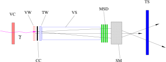
The polarimeter was installed in front of the LEPS spectrometer at the position used by the target. The LEPS drift chambers were used for detecting the electron and the positron. The magnet SM together with the LEPS drift chambers formed a pair spectrometer. The LEPS dipole magnet was turned off.
III.2 Photon beam
Figure 4 shows the photon energy spectrum detected by the tagger. The calculated photon polarization vs photon energy is shown in Fig. 5. It has a maximum value of 93% at the Compton edge of 2.4 GeV. The energy dependence of the polarization was taken into account in the extraction of the analyzing power (see section IV.2).


III.3 Trigger logic
The signals from VC, WV, TW and TS are used to form a polarimeter trigger signal (PT). The coincidence between PT and a tagger trigger signal was used to initiate a readout cycle of both the polarimeter and the LEPS electronics. The amplitude from the trigger wire chamber TW was recorded in both DAQs and used to cross check the synchronization of information.
III.4 Data collection
Measurements were done at two orientations of the laser polarizations - vertical and horizontal. The orientations were interchanged typically every 2 hours. The degree of the laser photon polarization was 99%. The typical tagger rate was 150 kHz, the wire chamber rates 20 kHz and the event rate 150 Hz. In the trigger rate the contribution from the unpolarized background of photons produced on the residual gas in the storage ring was below 2%.
IV Analysis and Results
IV.1 Data analysis
Only events with one hit in the tagger were considered. For reconstruction of the tracks in the MSD and the drift chambers first clusters were searched. After a cluster was recognized and its position determined, the hit pattern was used for a track search. We analyzed all combinations and selected two with best matching of the hit positions. The distribution of the residuals for the best combination has a peak, of which width allows to estimate the MSD spatial resolution to be 15 m. Events with two tracks in the MSD were used in the analysis of the pair angular and position distributions. The drift chamber and tagger information were used to calibrate the deflection parameter of the pair spectrometer. The energy of the electron and the positron were used to select pairs with . The separation between the electron and the positron tracks in the MSD () and the photon energy were used to calculate the reduced open angle , where is the distance between the converter and MSD, the electron mass.
IV.2 Results
The beam polarization effect in the azimuthal distribution (see eq. 1) of the pair plane is shown in Fig. 6 for events with a photon energy in the range 1.5-2.4 GeV.

The analyzing power of the reaction has a strong dependence on the open angle between the pair components. Figure 7 shows a corresponding experimental result. Two cases of the averaged analyzing power are also presented in this plot. These running averagies show how to select the low and the upper limits on the reduced open angle to minimize the sensitivity of the analyzing power to these cuts.
For the next step in the analysis we used only events with a reduced open angle in the range from 4 to 20. The asymmetry as a function of the photon energy is plotted in Fig. 8. The curve follows the dependence of the photon beam polarization as a function of the photon energy.


The selection of the pairs with almost equal and energies leads to a higher asymmetry as is shown in Fig. 9. The values of the analyzing power for these two cases are 0.119 and 0.192. They agree within 5% with calculations Woj03 for the thickness of the carbon converter used in our experiment (0.1mm).

V Conclusion
Here, we described the results of a polarimeter test at SPring-8/LEPS. For the first time the polarization effect in the pair photo-production from amorphous matter was observed in the GeV energy range. We demonstrated that a compact polarimeter for photon energies of several GeV can be constructed by using silicon micro-strip detectors. An analyzing power was observed of 0.192 for 0.1 mm carbon converter and near equal energies of the electron and the positron, which is within 5% of the expected value.
We acknowledge the crucial support of W. Briscoe, L. Cardman, and B. Mecking.
This work was supported in part by the National Science Foundation in grants PHY-0099487 for the North Carolina Central University and PHY-0072361 for the University of South Carolina and by DoE contract DE-AC05-84ER40150 under which the Southeastern Universities Research Association (SURA) operates the Thomas Jefferson National Accelerator Facility for the United States Department of Energy.
References
- (1) H. Olsen and L. C. Maximon, Phys. Rev. 114, 887 (1959); L. C. Maximon and H. Olsen, Phys. Rev. 126, 310-319 (1962).
- (2) C. N. Yang, Phys. Rev. 77, 722 (1950); J. H. Berlin and L. Madansky, Phys. Rev. 78, 623 (1950).
- (3) G. Barbiellin et al., Phys. Rev. Lett. 9, 396 (1962); H. Sasaki et al., Nucl. Instr. and Meth. 62, 45 (1968); M. Kobayashi and K. Kondo, J. Phys. Soc. Japan 28, 277 (1970); M. Kobayashi and K. Kondo, Nucl. Instr. and Meth. 104, 101 (1972).
- (4) T. Nakano et al., Nucl. Phys. A684, 71c (2001).
- (5) B. Wojtsekhowski et al., Polarimeter for High Energy Photons, JLab Technical Note 98-039, 1998.
- (6) B. Wojtsekhowski, D. Tedeschi, B. Vlahovic, Nucl. Instr. and Meth.515, 605 (2003).