Actuation of Micro-Optomechanical Systems Via Cavity-Enhanced Optical Dipole Forces
Abstract
We demonstrate an optomechanical system employing a movable, micron-scale waveguide optically-coupled to a high- optical microresonator. We show that milliwatt-level optical powers create micron-scale displacements of the input waveguide. The displacement is caused by a cavity-enhanced optical dipole force (CEODF) on the waveguide, arising from the stored optical field of the resonator. The CEODF is used to demonstrate tunable cavity-waveguide coupling at sub-mW input powers, a form of all-optical tunable filter. The scaling properties of the CEODF are shown to be independent of the intrinsic of the optical resonator and to scale inversely with the cavity mode volume.
Although light is usually thought of as imponderable, carrying energy but relatively little momentum, light can exert a large force per photon if confined to small structures. Such forces have recently been proposed Povinelli et al. (2005a, b) as a means to construct novel optomechanical components such as tunable filters, couplers, and lasers. Other theoretical studies of the nonlinear dynamics of these systems have shown them to be useful for performing optical wavelength conversion and efficient optical-to-mechanical energy conversionNotomi and Mitsugi (2006); Notomi et al. (2006). In the field of quantum physics, there has also been recent interest in using radiation pressure forces within micro-optomechanical resonators to help cool macroscopic mechanical oscillators to their quantum-mechanical ground state Gigan et al. (2006); Kleckner and Bouwmeester (2006); Arcizet et al. (2006); Schliesser et al. (2006). Here, we demonstrate an optomechanical system employing a movable, micron-scale waveguide optically-coupled to a high- optical microresonator. We show that milliwatt-level optical powers create micron-scale displacements of the input waveguide. The displacement is caused by a cavity-enhanced optical dipole force (CEODF) on the waveguide, arising from the stored optical field of the resonator. The CEODF is used to demonstrate tunable cavity-waveguide coupling at sub-mW input powers, a form of all-optical tunable filter. Finally, the scaling properties of the CEODF are shown to be independent of the intrinsic of the optical resonator, and to scale inversely with the cavity mode volume, indicating that such forces may become even more effective as devices approach the nanoscale.
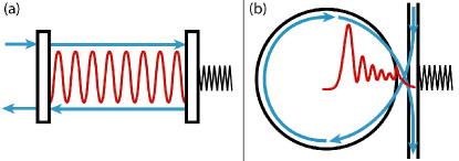
The ponderomotive effects of light within optical resonators have long been considered in the field of high-precision measurementBraginsky and Manukin (1977). The canonical system, shown in Fig. 1a, consists of a Fabry-Perot (FP) resonant cavity formed between a rigid mirror and a movable mirror attached to a spring or hung as a pendulumDorsel et al. (1983). A nearly-resonant optical field builds up in amplitude as it bounces back-and-forth between the mirrors and pushes on the movable mirror with each reflection, which detunes the FP cavity. The nonlinear dynamics associated with the displacement of the mirror and the build-up of internal cavity energy result in an “optical spring” effectMeystre et al. (1985). Under conditions in which the optical field cannot adiabatically follow the mirror movement, the radiation pressure force can drive or dampen oscillations of the position of the movable mirrorPai et al. (1999); Kippenberg et al. (2005); Marquardt et al. (2006)—this effect is the basis for some optomechanical cooling schemesGigan et al. (2006); Arcizet et al. (2006); Schliesser et al. (2006).
In contrast to the FP optomechanical system, the system studied here consists of a monolithic, whispering-gallery-mode (WGM) resonator coupled to an external waveguide. The waveguide is suspended (secured at two distant points) and behaves as if attached to a spring. Light evanescently couples into the resonator from the waveguide, as illustrated in Fig. 1b. The intra-cavity light intensity changes the waveguide position via an all-optical force on the waveguide due to the field of the resonator. The resulting movement changes the waveguide-resonator coupling-rate—rather than the cavity resonance condition as in the FP system—which is sensitive to the distance between the waveguide and resonator. Unlike the FP system, the optical force is derived from the gradient force, a result of intensity-dependent light shifts of electronic states in the dielectric external waveguideGordon and Ashkin (1980); Metcalf and van der Straten (1999). No complete correspondence between the FP system and the system in Fig. 1b can be made due to the external nature of the waveguide (the FP would require a mirror that could change its reflectivity in response to changing optical powerFermann et al. (1990)). This non-trivial difference also applies to a wide class of cavity geometries in which a non-resonant dielectric object loads the cavity.
In this work, the implementation of the optomechanical system of Fig. 1b consists of a high- silicon nitride (SiNx) microdisk resonator of diameter m and thickness nm. The resonator is fed optical power through an external waveguide formed from a micron-scale silica optical fiber taper. An optical micrograph of the micron-scale fiber taper in the near-field of the SiNx microdisk is shown in Fig. 2b, indicating the geometry of the taper-disk coupling. Fabrication of the microdisk and the taper are described in detail elsewhereBarclay et al. (2006); Michael et al. (2007).
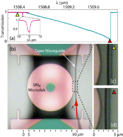
Figure 2a shows the transmission spectrum of a high- WGM of the microdisk at low (inset) and high power. At low powers ( W), the microdisk system behaves linearly. At higher powers, heating effects due to linear optical absorption within the SiNx microdisk result in thermo-optic bistability. In addition to the thermo-optic effect (which gives rise to an asymmetric, shark-fin-like feature in the transmission spectrum Carmon et al. (2004)), the on-resonance transmission depth changes significantly with input power. This effect can be visually correlated with movement of the waveguide on a magnified microscope image such as Fig. 2c-d. Displacements on the order of the diameter of the waveguide ( m) can be produced with an incident power of mW. The waveguide always moves towards the edge of the microdisk, with the movement disappearing when the waveguide is positioned far from the microdisk resonator.
We model the force by considering the potential energy, , of the waveguide due to the polarization induced by the field of the resonator. Using complex fields and assuming linear dielectric susceptibility, the time-averaged polarization energy of the waveguide due to a dipole moment per unit volume is
| (1) |
where is the geometric volume of the dielectric waveguide, is the waveguide material’s electric susceptibility and is the electric field of the microdisk WGM. The average stored cavity energy, , can be related to an effective mode volume of the WGM, , where is the refractive index of the resonator. All the information of field amplitudes is carried in and , which allows one to write
| (2) |
where is the unitless electric field eigenfunction of the WGM, normalized such that . From FEM simulations, we find for the WGM of resonance wavelength nm studied here (see Methods).
In the limit of small parasitic lossesBarclay et al. (2005), the steady-state internal energy in the microdisk resonator is given by, , where is the input power in the waveguide at the resonator; is the angular frequency of the input light; is the intrinsic quality factor of the WGM; and is the fractional waveguide transmission past the cavity. Fitting the spectrum of the WGM yields an unloaded, intrinsic -factor of .
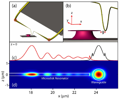
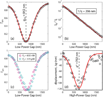
The on-resonance transmission () depends on the cavity-waveguide optical coupling- and loss-rates, , where is the extrinsic (waveguide-to-resonator) coupling-rate, and is the intrinsic cavity loss-rateSpillane et al. (2003). The fields of both the microdisk resonator and the taper waveguide decay exponentially outside of their geometric boundaries due to the evanescent nature of the fields there (see Figs. 3(c-d)). We thus expect to vary exponentially with the disk-taper gap, (shown in Fig. 3b); i.e. , where is nominally the “zero-gap” coupling-rate. In Fig. 4b we plot as extracted from the measured curve in Fig. 4a and unloaded -factor of the microdisk. shows the expected exponential dependence with gap, yielding a decay constant equal to nm-1 for the disk-taper system. The fully-characterized low-power transmission curve (Fig. 4a), can be used to infer the relative disk-taper gap from any value of on-resonance transmission, , given knowledge of whether the system is overcoupled or undercoupled.
Substituting in the exponential dependence of coupling on gap, one arrives at a dipole potential energy of the waveguide given by,
| (3) |
The integral in equation (3) can be approximated by , where is an effective decay constant, and is an effective volume of the waveguide. In what follows, we take , as predicted by a simple coupled-mode theory of the taper-microdisk systemManolatou et al. (1999) (as shown below, this assumption is borne out by experiment).
Although the amount of externally-coupled energy changes with the gap, the fast response rate of the optical cavity ( ns photon lifetime) allows the resonator dynamics to be adiabatically removed. In this approximation, describes a completely conservative energy landscape without hysteretic or dissipative characteristics. The effective optical force on the waveguide is,
| (4) |
We note that this force curve is significantly different from that of a closed system in which the optical dipole force would be given by the product of the stored cavity energy and the gradient of the microdisk mode’s evanescent near-field intensity profile. The maximum of this force occurs at a gap , and is given by
| (5) |
In this model, occurs on the overcoupled side of the critical coupling gap—not at , the point of maximum stored cavity energy.
To test the validity of the model, we measure the position-dependence of the steady-state force. Starting with the waveguide far from the microdisk resonator ( nm), we incrementally move the resonator toward the waveguide in 50 nm steps using an encoded DC motor stage. At each position of the motor, we measure at 650 nW and 370 W. Figure 4c shows the high- (cyan) and low-power (magenta) transmission curves. The actual position of the waveguide in the high-power measurement is extracted from the low-power data. The change in actual waveguide-resonator gap, , between the low- and high-power transmission curves is proportional to the force required to move the waveguide to its high-power position, assuming the mechanical spring constant () of the optomechanical system is linear. Thus, Fig. 4d is a plot of .
Figure 4d shows the fit to the force curve data using equation (4). As mentioned above, coupled mode theory predicts that ; this equality is confirmed here as is the best non-linear least-squares fit to the measured force curve when is left as a free parameter. The fit model also matches the measured recovery to zero force for small gaps, and has a peak force position ( nm), just on the overcoupled side of the zero transmission gap ( nm). The numerical evaluation of the optical force in equation (4) yields a prediction for the magnitude of the optical force on the taper waveguide and, from the fit of the measured force curve in Fig. 4d, an estimate of the taper’s mechanical spring constant. We find a peak optical force of 20 pN/mW of input power for the disk-taper system under study and a taper spring constant of pN/m.
Direct measurements of the mechanical properties of the taper waveguide were also performed. A diagram illustrating the geometry of the fiber taper waveguide used in these experiments is given in Figs. 3(a-b). Imaging of the fiber taper displacement with a microscope indicates that the optically-excited mechanical resonance of the taper is similar to the fundamental mode of an elastic wire, pinned at the corners of the “U”-shaped bend in the taper waveguide. As shown, the fiber taper waveguide is not a simple “U” shape, but rather has a small “dimple” ( m radius of curvature) at the taper’s center to allow local probing of planar devicesMichael et al. (2007). The torsional mode of the “dimple” does not appear to be excited. From the measured mechanical frequency ( Rad/s) and the physical mass of the taper’s “U” section ( kg), we arrive at pN/m (see Methods). This value differs by less than a factor of two from the optically-measured spring constant of the taper waveguide.
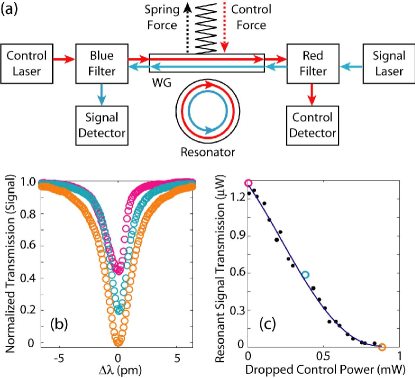
Applications of the CEODF include optical control of micro- and nano-optomechanical devices for the dynamic switching, filtering, or modulation of light. Figure 5a shows the schematic of a simple experiment to demonstrate all-optical tuning of the filter characteristics of the microdisk using the CEODF. In this scheme a red control field () counterpropagates with a blue signal field (), each of the fields resonant with a different mode of the microdisk (in this case, WGMs of the same radial order but azimuthal mode number difference ). The waveguide is pulled towards the resonator in proportion to the dropped control power, tuning the cavity-waveguide system from the undercoupled regime towards the overcoupled regime. In this way, the filter rejection level at the signal wavelength can be tuned by the control power level, as shown in Figs. 5(b-c). Using the thermo-optic bistability of the system, variation in the dropped control power is accomplished not by tuning the control power level, but rather by tuning the wavelength of the control laser. This provides an approximately linearly-tunable control; however, the resonance position for the signal is tuned simultaneously and must be tracked. By engineering a similar system in which the threshold power for thermo-optic bistability is much larger than the threshold power for optomechanical modulation, the same basic structures could be made to tune the cavity’s filter properties by adjusting only the input power of the control—without the need to track the signal resonance. Utilizing a microfabricated on-chip waveguideLee and Wu (2005), an equivalent system with high mechanical frequency (MHz to GHzHuang et al. (2003); Carmon and Vahala (2007)) could be used to produce fast, all-optical tuning or signal modulation.
Analysis of equation (5) indicates that the magnitude of the force does not scale with the intrinsic optical -factor (). This is a result of the interplay between the stored optical energy and the degree of cavity loading: increasing moves further from the disk, which exactly cancels the -enhancement of the internal field. The -independence of the force facilitates making systems insensitive to other nonlinearities which scale with (such as the thermo-optic bistability of the current devices). Indeed, early results with low- microdisks () of roughly the same size ( m) show large optical force effects with no observable thermo-optic bistability. Equation (5) also shows that the force scales inversely with . Therefore smaller devices, even with lower quality factors, give rise to a larger maximum force. Up to a factor of order unity, cancels, keeping the above scaling valid as devices approach the nano-scale. For example, in the case of planar two-dimensional photonic crystal nanocavitiesPainter et al. (1999) with cubic-wavelength-scale mode volumes, the optical forces can be expected to be two orders of magnitude larger than in the microdisk studied here, approaching the nN level. Such scaling behavior is applicable to a wide variety of geometries in which the CEODF acts on non-resonant dielectric objects in the near-field of the optical resonator and indicates an interesting path towards low-power, high-speed micro- and nano-scale actuators and transducers.
Methods
The fiber taper is created by locally heating (with a H2 torch) and drawing a standard SMF-28e silica fiber. An adiabatic taper is formed with a long ( mm), narrow diameter region () in which the evanescent field of the guided mode penetrates significantly into the air cladding. The fiber is then bent in a “U”-shape Barclay et al. (2004), with the tapered region at the end of the “U” and the two fiber ends separated by an adjustable gap to provide varying tension levels to the taper. In addition, a “dimpled” region is created in the geometric center of the “U” region in order to access the disk, which resides in a trench. The fiber tension is mechanically adjustable; tension is optimized to accentuate optically-induced fluctuations while maintaining the waveguide’s stability (the stability of the taper waveguide is exemplified in Fig. 4a).
Fiber-pigtailed, external cavity, tunable lasers operating over the and nm wavelength bands are used to couple optical power into the taper waveguide. The polarization of the guided mode in the taper is controlled via three adjustable fiber loops. Excitation of the whispering-gallery modes (WGMs) of the microdisk is performed by positioning the fiber taper in the equatorial plane of the microdisk and approaching the near-field of the microdisk from the side. Positioning of the disk (-) and taper () is accomplished using DC motors with nm encoded resolution.
The low-power data in Fig. 4c allows the construction of a transmission curve that is identical to the transmission curve in Fig. 4a; it is nevertheless taken again, concurrently with the high power data, to cancel any drift in the taper-disk gap over the course of the measurement.
The particular WGM used in this study has six radial antinodes (, , ; shown in Fig. 3c-d juxtaposed to the waveguide mode) and was chosen due to its high intrinsic (unloaded) and favorable taper-coupling characteristics (phase-matching). Individual WGM modes can be identified Borselli et al. (2004) via the following characteristics: the free-spectral range between modes, the radiation-limited of modes, and the strength of coupling to the taper waveguide (degree of phase-matching). The experimentally measured quantities are matched to accurate FEM simulations of the disk modes. The mode’s identification was experimentally verified by moving the waveguide over the surface of the disk and measuring the characteristic radial pattern of the mode through changes in the taper-disk coupling-rate, .
We measured the mechanical resonance frequency by driving the taper waveguide with an electro-acoustical transducer in close proximity to the waveguide. The response of the waveguide appears as a clearly-visible oscillation in the on-resonance optical transmission of the cavity-waveguide system, well above the noise floor. By measuring this response against the frequency of the driving waveform, we extract the mechanical resonance frequencies. The effective mass of the oscillator is approximated by the mass of the fused-silica taper (length mm, diameter exponentially tapering from to m) weighted by the fundamental mechanical eigenfunction.
Acknowledgements
The authors sincerely thank Thomas Johnson, Paul Barlcay, and Kartik Srinivasan for many fruitful discussions and helpful feedback.
References
- (1)
- Povinelli et al. (2005a) M. L. Povinelli, M. Loncar, M. Ibanescu, E. J. Smythe, S. G. Johnson, F. Capasso, and J. D. Joannopoulos, Opt. Lett. 30, 3042 (2005a).
- Povinelli et al. (2005b) M. L. Povinelli, S. G. Johnson, M. Loncar, M. Ibanescu, E. J. Smythe, F. Capasso, and J. D. Joannopoulos, Opt. Express 13, 8287 (2005b).
- Notomi and Mitsugi (2006) M. Notomi and S. Mitsugi, Phys. Rev. A 73, 051803(R) (2006).
- Notomi et al. (2006) M. Notomi, H. Taniyama, S. Mitsugi, and E. Kuramochi, Phys. Rev. Lett. 97, 023903 (2006).
- Gigan et al. (2006) S. Gigan, H. R. Bhm, M. Paternostro, F. Blaser, G. Langer, J. B. Hertzberg, K. C. Schwab, D. Buerle, M. Aspelmeyer, and A. Zeilinger, Nature 444, 67 (2006).
- Kleckner and Bouwmeester (2006) D. Kleckner and D. Bouwmeester, Nature 444, 75 (2006).
- Arcizet et al. (2006) O. Arcizet, P.-F. Cohadon, T. Briant, M. Pinard, and A. Heidmann, Nature 444, 71 (2006).
- Schliesser et al. (2006) A. Schliesser, P. Del’Haye, N. Nooshi, K. Vahala, and T. Kippenberg, Phys. Rev. Lett. 97, 243905 (2006).
- Braginsky and Manukin (1977) V. B. Braginsky and A. B. Manukin, Measurements of Weak Forces in Physics Experiments (The University of Chicago Press, Chicago, IL, 1977).
- Dorsel et al. (1983) A. Dorsel, J. McCullen, P. Meystre, E. Vignes, and H. Walther, Phys. Rev. Lett. 51, 1550 (1983).
- Meystre et al. (1985) P. Meystre, E. M. Wright, J. D. McCullen, and E. Vignes, J. Opt. Soc. Am. B 2, 1830 (1985).
- Pai et al. (1999) A. Pai, S. Dhurandhar, P. Hello, and J.-Y. Vinet, Eur. Phys. J. D 8, 333 (1999).
- Kippenberg et al. (2005) T. J. Kippenberg, H. Rokhsari, T. Carmon, A. Scherer, and K. J. Vahala, Phys. Rev. Lett. 95, 033901 (2005).
- Marquardt et al. (2006) F. Marquardt, J. G. E. Harris, and S. M. Girvin, Phys. Rev. Lett. 96, 103901 (2006).
- Gordon and Ashkin (1980) J. P. Gordon and A. Ashkin, Phys. Rev. A 21, 1606 (1980).
- Metcalf and van der Straten (1999) H. J. Metcalf and P. van der Straten, Laser Cooling and Trapping, Graduate Texts in Contemporary Physics (Springer, New York, NY, 1999).
- Fermann et al. (1990) M. Fermann, F. Haberl, M. Hofer, and H. Hochreiter, Opt. Lett. 15, 752 (1990).
- Barclay et al. (2006) P. E. Barclay, K. Srinivasan, O. Painter, B. Lev, and H. Mabuchi, Appl. Phys. Lett. 89, 131108 (2006).
- Michael et al. (2007) C. P. Michael, M. Borselli, T. J. Johnson, C. Chrystal, and O. Painter, arxiv:physics/0702079 (2007).
- Borselli et al. (2005) M. Borselli, T. J. Johnson, and O. Painter, Opt. Express 13, 1515 (2005).
- Carmon et al. (2004) T. Carmon, L. Yang, and K. J. Vahala, Opt. Express 12, 4742 (2004).
- Barclay et al. (2005) P. E. Barclay, K. Srinivasan, and O. Painter, Opt. Express 13, 801 (2005).
- Spillane et al. (2003) S. M. Spillane, T. J. Kippenberg, O. J. Painter, and K. J. Vahala, Phys. Rev. Lett. 91, 043902 (2003).
- Manolatou et al. (1999) C. Manolatou, M. J. Khan, S. Fan, P. R. Villeneuve, H. A. Haus, and J. D. Joannopoulos, IEEE J. Quan. Elec. 35, 1322 (1999).
- Lee and Wu (2005) M.-C. M. Lee and M. C. Wu, IEEE Phot. Tech. Lett. 17, 1034 (2005).
- Huang et al. (2003) X. M. H. Huang, C. A. Zorman, M. Mehregany, and M. L. Roukes, Nature (London) 421, 496 (2003).
- Carmon and Vahala (2007) T. Carmon and K. J. Vahala, Phys. Rev. Lett. (2007), in press.
- Painter et al. (1999) O. Painter, J. Vučković, and A. Scherer, J. Opt. Soc. Am. B 16, 275 (1999).
- Barclay et al. (2004) P. E. Barclay, K. Srinivasan, M. Borselli, and O. Painter, Opt. Lett. 29, 697 (2004).
- Borselli et al. (2004) M. Borselli, K. Srinivasan, P. E. Barclay, and O. Painter, Appl. Phys. Lett. 85, 3693 (2004).
- (32)