Micro Drift Chamber as a precise vertex detector for the DIRAC experiment.
Abstract
A possible implementation of the Micro Drift Chamber (MDC) technique as a high resolution vertex detector in the upstream part of the DIRAC spectrometer was investigated in this paper. Simulations of different MDC layout were performed with the help of GARFIELD package. Based on the results of simulation the optimal chamber geometry and the gas mixture were selected.
One cell prototype was produced and its characteristics were measured at different particle fluxes, various gas pressures and thresholds of electronics.
Data observed together with expected coordinate resolution of MDC allow to employ such detector in different field of application including the DIRAC experiment.
keywords:
Vertex detector, drift chamber, multiwire chamberPACS:
29.40.Cs , 29.40.Gx, ††thanks: Supported by INTAS YSF Ref. Nr. 05-109-5080 , ,
1 Introduction
The DIRAC experiment [1] aims to measure with high precision the lifetime of atoms as well as atoms consisted of charged and -mesons [2]. The experiment is carrying out at CERN Proton Synchrotron on the extracted proton beam. The DIRAC setup (fig. 1) [3] is a magnetic double arm spectrometer. It consists of a proton beam line, target station, secondary particles channel, spectrometer magnet and upstream and downstream detectors including 28 planes of the Drift Chambers as a main tracking system.

Events investigated in the experiment are characterized by pairs of particles with small relative momentum (). In the upstream part of the spectrometer the distance between such particles is . For their registration the MSGC, SFD and IH detectors are used. But the absence of a rigorous tracking system, which is able to register reliably the close tracks, affects the experiment efficiency. Therefore it seems quite reasonable to supplement the experimental setup with such system. Amount of information from these detectors is also extremely large and makes difficulties for data acquisition and analysis. Traditional solid-state and gaseous multi-channel vertex detectors are universal instruments appropriate for experiments with high particle multiplicity. At once there are many experiments where multiplicity is not so high, but it is necessary to detect pairs of the close particles and measure their coordinates with high accuracy. The DIRAC setup belongs to this type of experiment.
Aim of the present work is investigation of the possibility to develop a vertex detector based on conventional technique of the drift chamber with small drift distance - micro drift chamber (MDC).
Next in the paper we describe the principle of this detector operation, which thoroughly enables to meet the requirements of the DIRAC and similar experiments. The results of the detector properties simulation using Garfield package are presented. Some data obtained in experimental investigation of one-cell prototype of the MDC are shown.
2 Features of two close tracks registration in drift chamber
Let us consider how particles are detected in a drift chamber cell. In case of one particle primary ionization electrons drift to the anode wire and initiate the avalanche process. This avalanche occupies part of the anode wire and inhibits for some time the detection of another particle close-by in space. Therefore, if two particles cross the cell simultaneously, one of them could not be detected because either it does not produce an avalanche or due to electronics dead time.
These restrictions are important in case of using one plane of the drift chamber. Complementary plane shifted by half a cell width, which is usually employed to eliminate a left-right ambiguity, in addition allows to resolve the problem of two close tracks registration (fig. 2). As one can see in the figure, if two tracks cross one cell, then the signal in each plane will be produced by that particle, which is closer to the wire. Therefore both particles will be registered.
Using of double planes chamber besides the possibility of two close tracks registration enables also interesting opportunity to organize fast and effective trigger for such events selection. If one particle cross two adjacent cells the sum of the drift times for these cells is equal to the maximum drift time. In case of two tracks this sum will decrease with increasing the distance between these tracks. If we put the signals from these cells to the unit, which operates as a mean-timer, then we will get a time spectrum with the peak corresponding to the case of one particle and the rest part of the spectrum corresponds to more than one particle. Then if we gate the signals from mean-timers through the time window one can to select the required events on the fly. Efficiency of this trigger and its possible realization in the DIRAC experiment were represented in [4].

3 Choice of MDC geometric parameters and operation mode
Lateral dimension of the secondary particle beam in the supposed MDC region is and particle flux is . It is necessary to minimize the probability of tracks overlaying from successive interactions of beam particle with target. Taking into account that number of channels in one MDC plane should be multiple of 16 and one cell dimension should be small enough to distinguish efficiently two close tracks, the distance between signal wires has been chosen .
In a number of articles [6]-[9] the possibility of drift chamber with small drift distance () operation in high gas gain mode () and high counting rate () was shown. Drift chamber operation in high gas gain mode has a number of advantages. Big amplitude of signal enables to exploit readout electronics with high threshold as well as short pulses with rapid front improve the time properties of a chamber.
Next in this section the analysis of the cell geometry and gas mixture, performed by the use of GARFIELD package [5] are given.
3.1 Drift cell geometry
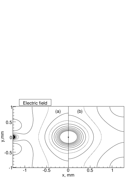
We considered two possible layouts of MDC cell (fig. 3). It is supposed, that anode wires are under the zero, cathode planes and field formative electrodes under the common negative potential.

In fig. 4 one can see an electric field map inside different drift cell layouts. The cell with potential wires has rather great regions with low value of electric field, which make worse the time properties of the chamber. Other disadvantage of this layout is the possibility to hit also an adjacent anode wire in case of particle crosses the sensitive plane near potential wire. This is not desirable in high counting rate condition.
3.2 Gas mixture
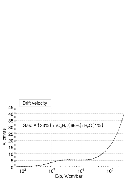
We choose for the Micro Drift Chambers the mixture: . This gas mixture is used in DIRAC Drift Chambers system. It has the next preferences:
-
•
stable work in high gas gain mode;
-
•
wide plateau () of efficiency;
-
•
fast leading-edge time of pulses ();
-
•
weak drift velocity dependence on electric field practically for whole field value interval inside the drift cell. (fig. 5).
For this gas mixture at normal pressure the mean number of primary ionization clusters generated by charged pion with momentum is . If particles cross the cell near the anode wire then fluctuations of primary ionization spread significantly drift times. This spread could be reduced by increasing the pressure inside the chamber. As it will be shown below increase of pressure in addition leads to more stable chamber operation.
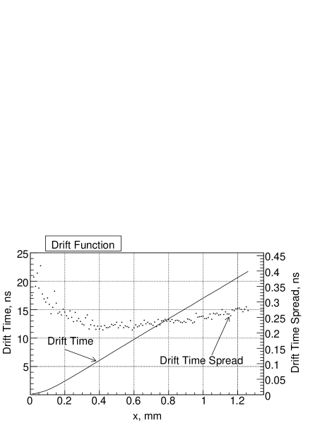
In fig. 6 the results of drift function simulation for the selected MDC layout and gas mixture at pressure are shown. As one can see, the drift function is close to linear, maximum drift time is and the spread of the drift times provided by primary ionization fluctuations, diffusion and other processes in the gas does not exceed .
4 One cell prototype tests of the Micro Drift Chamber
To study properties of the Micro Drift Chamber the one cell prototype was produced with potential strips (fig. 3b). It consists of a signal beryllium bronze wire of diameter , potential strips and cathode planes made of Mylar foil thick coated by carbon with conductivity . The drift cell dimensions are . The prototype was placed into the pressurized box to vary the pressure inside the cell.
We used double scintillation counter telescope and collimated radioactive source to measure chamber characteristics.
Efficiency and single counting rate curves of MDC cell were measured at different values of particle flux, pressure and threshold of electronics. Also time spectra were measured.
Particle flux was defined by distance between the radioactive source and collimator and varied within: .
The hit wire signals after preamplifier went to the discriminator and then to the coincidence circuit, where scintillation counter signals also came, and to the counter. Thresholds of discriminator for MDC signal was: and .
The chamber was filled with gas mixture: . The measurements were performed at three values of absolute pressure inside the chamber: . It was found that the pressure increasing leads to more stable operation of the detector. The efficiency plateau expanded, pulse shape became better and drift times spread was reduced.
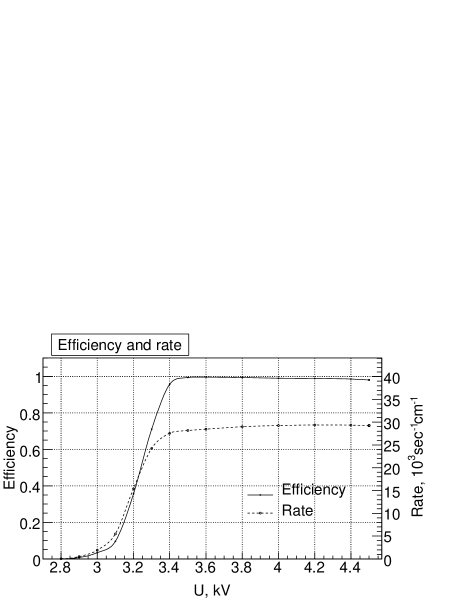
In fig. 7 typical efficiency and single counting curves measured at pressure and threshold of discriminator are shown.
Also the MDC time spectra were obtained at different values of pressure, threshold of electronics and voltage corresponded to efficiency plateau at given threshold. Measured spectra have rather complicated shape, which could be explained by the impossibility to provide the even irradiation of the drift cell due to low energy of electrons. Therefore the time spectra is not shown here, because their shape don’t provide information about drift function form. At once the width of the spectra is around , which corresponds to the maximum drift time calculated by GARFIELD package.
5 Conclusion
In this work we have studying the properties of the drift chamber with small drift distance prototype operating in high gas gain mode from point of view their application as a coordinate detector in the upstream part of the DIRAC setup.
Taking into account the experimental requirements and GARFIELD simulation results the optimal chamber layout and gas mixture were chosen. The one cell prototype of the drift chamber was produced and its characteristics were measures. These measurements were performed with radioactive source at various gas pressure inside the drift cell, threshold of the discriminator and particle flux through the drift cell.
It was shown that the chamber operates more stable at increased pressure. At , counting rate per wire unit of length up to and threshold the efficiency plateau width is few hundreds volts.
The data obtained equally with expected coordinate resolution make it possible to employ the Micro Drift Chamber for a number of applications including the DIRAC experiment.
The next step directed to development of the precise vertex detector for the DIRAC experiment is the double-plane prototype production and testing on the beam to check the stability of the chamber in hard radiation condition and estimation of the main characteristics of the detector: efficiency, coordinate resolution and double track resolution.
References
- [1] B.Adeva et al., J. Phys. G: Nucl. Part. Phys. 30 (2004) 1929.
- [2] B.Adeva et al., First observation of atom and its lifetime measurement, CERN/SPSC 2000-032, SPS/P284, Add.2, Geneva 2000.
- [3] B.Adeva et al., Nucl.Instr.and Meth. A 515 (2003) 467.
- [4] S.Vlachos, The Drift Distance Trigger, DIRAC note 02-12.
- [5] R.Veenhof, Garfield, a drift chamber simulation program, http://consult.cern.ch/writeup/garfield.
- [6] A.H.Walenta, Nucl.Instr.and Meth. 217 (1983) 65.
- [7] S.Majewski et al., Nucl.Instr.and Meth. 217 (1983) 265.
- [8] I.E.Chirikov-Zorin et al., Nucl.Instr.and Meth. A 260 (1987) 142.
- [9] S.V.Erin et al., Nucl.Instr.and Meth. A 283 (1989) 682.