A Multiwire Proportional Chamber for Precision Studies of Neutron Decay Angular Correlations
Abstract
A new multiwire proportional chamber was designed and constructed for precision studies of neutron decay angular correlations. Its design has several novel features, including the use of low pressure neopentane as the MWPC gas and an entrance window made of thin Mylar sheet reinforced with Kevlar fibers. In the initial off-line performance tests, the gas gain of neopentane and the position resolution were studied.
keywords:
Neutron decay , multiwire proportional chamber , low energy electron detectionPACS:
29.40.Cs , 23.20.En, , , ††thanks: Present address: Department of Physics, The University of Winnipeg, Winnipeg, Manitoba, R3B 2E9 , , ††thanks: Present address: Massachusetts Institute of Technology, Cambridge, MA ††thanks: Present address: Harvard University, Cambridge, MA
1 Introduction
Precision studies of neutron decay offer an excellent means to test the foundation of the Standard Model of electroweak interactions and to search for what may lie beyond it. In particular, the angular correlation between the neutron spin and the electron momentum (characterized by the coefficient ) in polarized neutron decay provides important input for testing the unitarity of the CKM matrix [1]. Recent technological advancements, including the realization of superthermal ultracold neutron sources [2, 3], have made experiments with a precession of within reach. Consequently, it is imperative to control possible systematic effects at the 0.1% level.
A typical experimental arrangement for coefficient measurements involves measuring the forward-backward asymmetry of electron emission with respect to the neutron spin in polarized neutron decay. Possible sources of systematic effects include polarization determination, background, and detector effects such as electron backscattering. With regard to the detector effects, most of the previous experiments used plastic scintillation counters as the detector for the decay electron. However, due to the small end point energy of the electron spectrum ( keV), a significant fraction () of electrons from neutron decay directed to one detector can backscatter from the surface of the detector and are detected by the other detector. A non-negligible fraction of the backscattered electrons leave undetectably small energy deposition in the first detector, hence introducing an error in the asymmetry determination. These electrons are called missed backscattered electrons.
One way to reduce the fraction of the missed backscattered electrons, and hence the effect of such events, is to use a detector that is sensitive to smaller energy deposition and can therefore have a lower energy threshold. In general, gas proportional counters are sensitive to a smaller energy deposition than plastic scintillation counters are. For a gas counter, an energy deposition of eV is necessary to create one primary electron-ion pair, which generates on average four secondary electron-ion pairs. With a moderate gas gain of 104 and an amplifier gain of 10 V/pC, one obtains an output pulse of mV. Therefore, an energy deposition of 100 eV can be relatively easily detected. On the other hand, for a plastic scintillation detector, an energy deposition of 100 eV is necessary to create one photon inside the scintillator. If a typical value of 15% for the photocathode quantum efficiency of the photomultiplier tube (PMT) and a rather generous value of 25% for the light collection efficiency are assumed, we obtain a 2.5 keV energy deposition for a single photoelectron event.
A detector system comprised of a thin low pressure multiwire proportional chamber (MWPC) placed in front of a plastic scintillator serves as an ideal detector: the thin MWPC provides sensitivity to backscattered events with small energy deposition while the plastic scintillator provides the total energy information as well as the timing information, which is of vital importance in analyzing a class of events in which both detectors record a hit as a result of backscattering. In addition, the position information from the MWPC can be used to apply a fiducial volume selection, which is of vital importance in experiments that use ultracold neutrons (UCN). Also, by requiring a coincidence between the MWPC and the scintillation counter for the event trigger, the sensitivity to rays, one of the major background sources in previous experiments, can be reduced because of the relatively low sensitivity of MWPCs to rays.
The UCNA experiment [4], currently being commissioned at Los Alamos National Laboratory, aims at a 0.2% measurement of the coefficient using UCN, and uses such a combination as the detector.
In this paper, we describe the design and construction of the MWPC developed for the UCNA experiment, and report the results from the initial offline performance tests. The design and construction of the plastic scintillation detector, together with the performance of the MWPC as installed in the UCNA spectrometer will be reported in a later publication [5].
2 Design and construction
2.1 General considerations and design overview
In the UCNA experiment, UCN are produced by the LANSCE solid deuterium UCN source, sent through a polarizer/spin flipper, and then introduced into a decay volume. The wall of the decay volume is a 3 m-long diamond coated quartz cylinder 10 cm in diameter. The decay volume is in the warm bore of a superconducting solenoidal magnet (SCS), which provides a holding field of 1 T. The decay electrons spiral along the magnetic field lines towards one of the detectors, and then enter the field expansion region, where the magnetic field is reduced to 0.6 T. As an electron enters the field expansion region, the energy associated with the angular motion of the electron is transfered to longitudinal motion in order to conserve angular momentum as the diameter of the spiral increases due to the reduced field. This reduces the incident angle of the electron onto the detector surface (reverse of the magnetic mirror effect) and suppresses backscattering. The detectors are placed in a region where the expanded field is uniform. The schematic of the UCNA experiment is shown in Fig. 1.
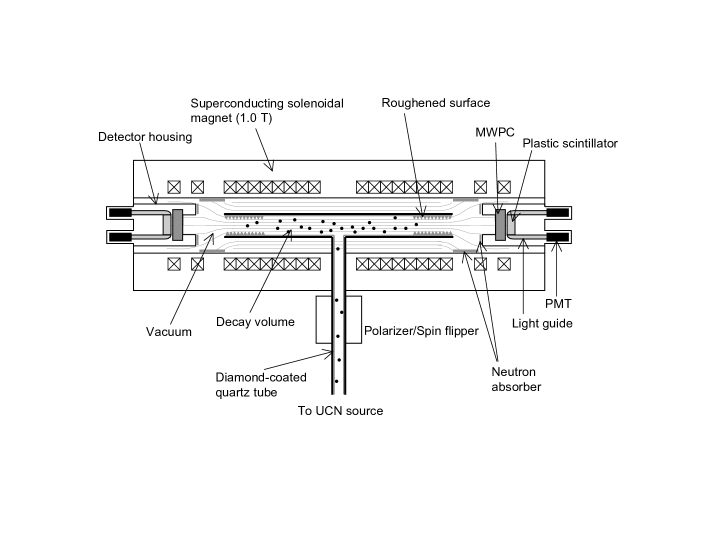
The function of the UCNA MWPC is two-fold: 1) to minimize the missed backscattered events, and 2) to provide position information. The latter is necessary because, unlike the previous measurements that used a cold neutron beam, in the UCNA experiment the UCN fill the decay volume. Therefore it is important to place a fiducial volume cut to reject events in which the decay occurred near the wall of the decay tube where it is likely for the electron to hit the wall.
A general consideration for minimizing missed backscattered events results in the following requirements for the design of the MWPC, in particular for the windows and the gas.
-
•
The entrance and exit windows have to be thin.
-
•
The gas has to be at low pressure, and has to consist of relatively heavy molecules made of low (=atomic number) atoms.
The requirements for the windows is obvious as any event in which the electron gets backscattered from the entrance window without getting into the gas volume will become a missed backscattered event. The gas pressure has to be low in order to make the entrance window thin, since it separates the MWPC gas volume from the spectrometer vacuum. Also, in order to minimize the backscattering, the gas should only contain atoms with low (=atomic number), since the total backscattering fraction is larger for a larger [6]. At the same time, in order to have a high enough detection efficiency, the MWPC gas has to have a reasonable electron density. This calls for a gas that consists of relatively heavy molecules made of light atoms.
Furthermore, there are two requirements for the UCNA MWPC design that are specific to the UCNA experiment. These are requirements for the position resolution and the actual geometrical size of the MWPC.
-
•
The maximum diameter of the spiral of the electron trajectory in the field expansion region is 6.6 mm. In order to perform a fiducial volume selection with a minimum loss of statistics, a position resolution of mm is required.
-
•
Because of the field expansion factor of 0.6 (0.6 T/1.0 T), the 10 cm diameter cross section of the decay volume maps to a circle with cm diameter in the field expansion region. On the other hand, the diameter of the warm bore the SCS magnet is 25.4 cm. Therefore, the UCNA MWPC has to have an effective area larger than 14 cm in diameter and has to fit in the warm bore with a diameter of 25.4 cm.
There is an additional consideration associated with the exit window. In the UCNA experiment, the exit window separates the MWPC gas volume from the volume in which the plastic scintillation detector is placed. The exit window can be made thin by filling the volume in which the plastic scintillator is placed with a gas that is of the same pressure as the MWPC gas.
Below, we will discuss each of these aspects of the design in more detail.
2.2 Mechanical construction
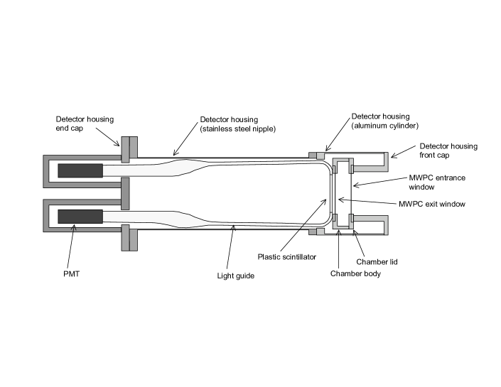
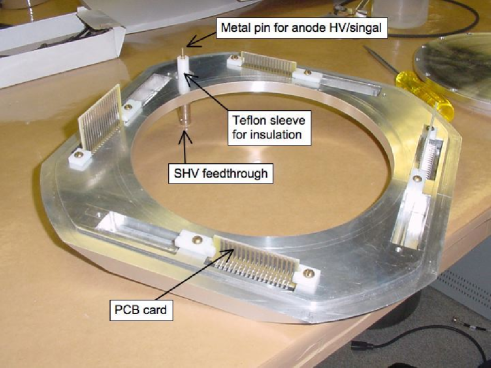
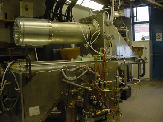
Figure 2 shows the cross section of the detector assembly, which in normal operation is inserted into the vacuum inside the SCS warm bore. Figure 3 shows the cross section of the MWPC and Figs. 4 and 5 are photographs of the MWPC. The chamber body and the chamber lid, both made of aluminum, constitute the body of the MWPC itself and enclose the MWPC gas, which is 100 torr neopentane (see section 2.3). The MWPC, the plastic scintillator, the light guide system, and the photomultipliers are housed in the detector housing. The detector housing consists of a about 25 in. long stainless steel nipple with an outer diamter of 10.5 in., an aluminum cylinder with an outer diameter of about 12 in., an end cap and a front cap made of aluminum. The stainless steel nipple and the aluminum cylinder are connected via 12-in. conflat flanges. The aluminum cylinder is welded onto a 12-in. flange made of explosion bonded aluminum-stainless steel bi-metal.
The detector housing is filled with 100 torr nitrogen. This is to minimize the pressure difference across the MWPC back window so that the back window can be thin. The space enclosed by the aluminum cylinder, the front cap, and the chamber lid houses the preamplifier for the MWPC readout and the HV systems for the MWPC operation. The difficulties associated with operating the HV system in a 100 torr nitrogen environment will be discussed in Section 2.5.
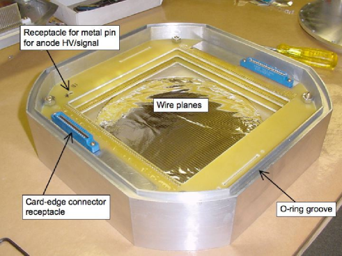
The chamber body, the chamber lid, the front cap are designed so that when the front cap is mounted on the aluminum cylinder it pushes the chamber lid making the o-ring seal between the chamber body and the chamber lid, the o-ring seal between the chamber lid and the front cap, and the o-ring seal between the front cap and the aluminum cylinder. Also it makes the electrical connection between the connectors on the chamber lid and the wire planes when the front cap is mounted on the aluminum cylinder pushing the chamber lid on the chamber body (See Figs. 3 and 5).
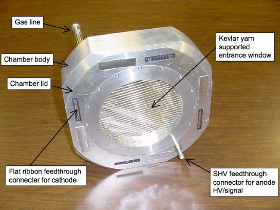
Shown in Fig. 6 is a photograph of the detector assembly and the gas panel.
2.3 Wire chamber gas
The requirements discussed earlier that the wire chamber gas consist of relatively heavy molecules made of low atoms and practical requirements (availability, affordability, etc) limited our choices for the gas almost uniquely to heavy hydrocarbon gases.
We chose neopentane (C5H12, also known as 2,2-Dimethylpropane) because of the high vapor pressure at room temperature (1125 torr). Typically we operated the wire chamber at 100 torr, which is safely below the vapor pressure. Also, as discussed below, we were able to develop a thin window that can safely withstand a 100 torr pressure difference. Neopentane at 100 torr has a electron density of /cm3. For comparison, P10 gas at 1 atm has an electron density of /cm3. Thus we expect a reasonably similar detection efficiency for 100 torr neopentane compared to 1 atm P10 gas, provided that we get a reasonably good gas gain and charge collection.
We note that n-pentane (normal pentane, C5H12) has already been used as a proportional chamber gas. Ref [7] discusses the use of gas mixtures of n-pentane-CO2, n-pentane-CO2-CH4, and n-pentane-CO2-CF4, while Ref. [8] discusses the use of various hydrocarbon gases such s isobutane, ethylene, n-pentane, and n-heptane at very low pressures ( torr). Although n-pentane is more cost effective than neopentane, it is not a practical choice for the following reasons:
-
•
The high reactivity, which would considerably limit the material allowed for the construction of the MWPC.
-
•
The low vapor pressure (424 torr at 20∘C), which would make the operation of the gas panel more demanding to avoid accidental liquefaction of the gas.
We will discuss the measured properties of neopentane as a wire chamber gas in Section 3.1
2.4 Wire plane construction
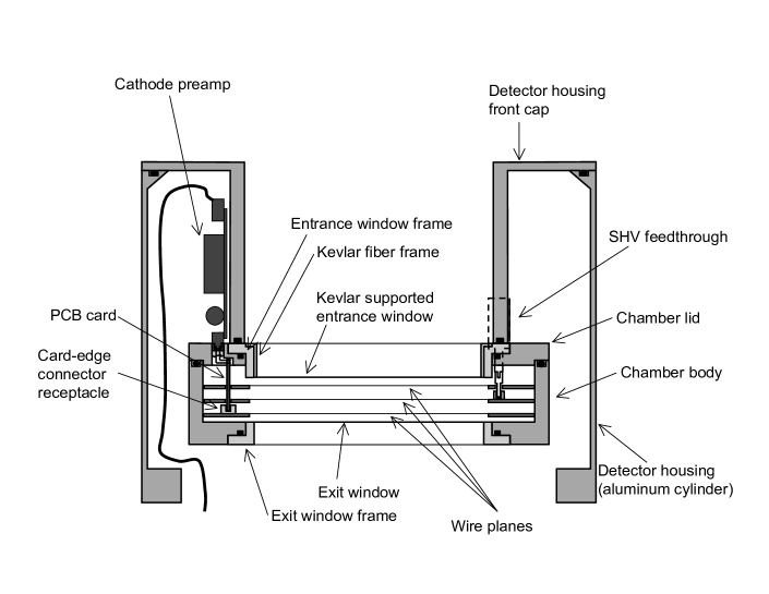
Heavy hydrocarbon gas such as isobutane is commonly used as a quencher gas, not as the main component of the wire chamber gas. In order to obtain a high enough gain from neopentane, which is also a heavy hydrocarbon gas, a wire with a small diameter has to be used for the anode wire plane. We chose to use gold-plated tungsten wires with a diameter of 10 m. 64 anode wires are strung with a 2.54 mm spacing, giving an effective area of 163 mm 163 mm, and are soldered onto a 0.092-in. thick FR4 glass epoxy frame. A tension of 9 gf, which is about 80% of the breaking point of the wire, was applied to each wire. All the anode wires are connected together by conductor tracks etched onto the FR4 glass epoxy plate, which are then connected to the HV resistor located outside the MWPC through an SHV feedthrough connector mounted on the chamber lid (see Sections 2.2 and 2.5 and Fig. 3).
In order to minimize electron backscattering, we chose to use wires also for the cathode planes, instead of more conventionally used thin strips of conductor etched on a substrate such as Mylar sheet [9]. The entrance and exit windows cannot be used as the cathode planes because the thin windows bow out by up to 1 cm (as measured at the center) due to the pressure difference across the windows. Also, the use of wires instead of conductor strips etched on a thin substrate facilitated the pump-out operation necessary prior to filling the MWPC with 100 torr neopentane.
Gold-plated aluminum wires 50 m in diameter were used for the cathode planes. Each cathode plane has 64 wires, strung with a 2.54 mm spacing with a 50 gf tension and soldered onto a 0.092-in. thick FR4 glass epoxy frame. Every four neighboring cathode wires are connected to one conductor strip etched on the FR4 glass epoxy plate, which then was connected to a card edge connector receptacle mounted on the FR4 epoxy plate. (There are 16 strips on each cathode plane.) The card edge connectors then provide a connection to the outside of the MWPC through feedthrough connectors on the chamber lid, on which Multi Channel Systems CPA16 amplifier carrier boards are mounted [10] (See Sections 2.2 and 2.6).
Wire planes were constructed using a wire-winding machine built according to Ref. [11]. The wire-winding machine was originally built for time projection chambers for the DRIFT dark matter search experiment [12]. We modified it replacing the weight that provides a constant tension to the wire with a hysteresis clutch/brake [13] which provides a constant torque, for a simpler operation. The wire was wound onto a frame made of aluminum, and then transfered onto the G10 frame.
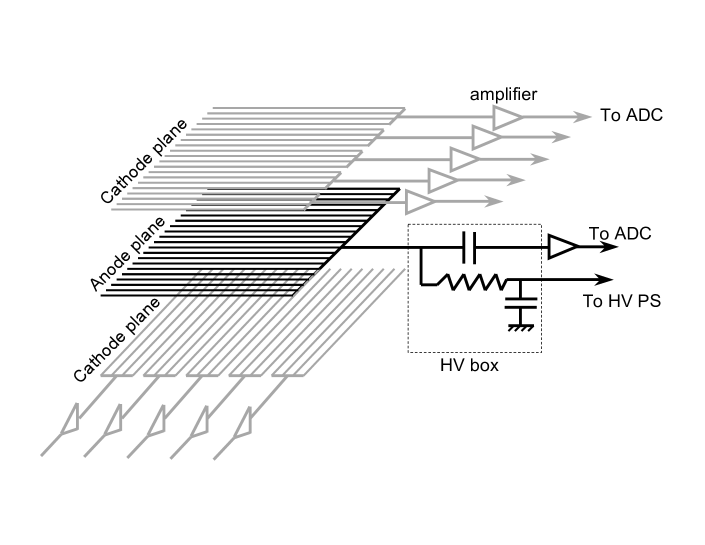
The distance between the anode plane and a cathode plane was chosen to be 10 mm, about 4 times the anode wire spacing [14]. The two cathode planes are mounted in such a way that the wires on one plane run perpendicular to the wires on the other plane, thus providing positional information in both directions that are perpendicular to the axis of the SCS spectrometer (see Fig. 7).
2.5 Bias High Voltage Systems
In order to collect the charge deposited between the windows and the cathode planes, the cathode planes are designed so that they can be held at a positive potential (up to 400 V) with respect to the windows which are grounded. The anode plane then is held at a positive potential ( 2700 V) with respect to the cathode planes.
The anode bias high voltage is supplied through a 25 M resistor (See Fig. 7). A 6.8 nF HV capacitor was inserted between the ground and the HV and served as a filter. The 25 M resistor, the 6.8 nF capacitor, and the 3.3 nF decoupling capacitor were all enclosed in a box (“HV box”) that was filled with Araldite 2011 epoxy [15] to prevent discharge due to the low pressure (100 torr nitrogen) environment.
The high voltage to the HV box was provided through an SHV cable that must be operated in the 100 torr nitrogen atmosphere. We found that most of the commercially available SHV cables failed in this low pressure environment. Detailed tests revealed that for some cables this failure was due to the SHV connectors themselves (SHV connectors from some manufactures always failed), and for others this was due to the way cables were assembled. We used SHV cables that were obtained from Dielectric Sciences [16].
2.6 Readout method and electronics
The basic readout method is shown in Fig. 7. As discussed in section 2.4 the signals from all the anode wires are summed on the anode wire plane, providing the information on the total energy deposited in the MWPC. The signals from every four neighboring cathode wires are summed, giving 16 channels to read out for each cathode plane. For the given cathode-anode plane distance (10 mm), the distribution of the induced charge on the cathode planes has a width of about 2 cm (FWHM), thus three to four cathode strips (each strip is a collection of four neighboring cathode wires) receive a detectable signal for each hit on the MWPC. The center of gravity of the signals of each cathode plane provides the coordinate of the location of the avalanche in the direction perpendicular to the cathode wire. Combining the information from both cathode planes determines the location of the avalanche.
The summed anode signal is extracted to the outside of the MWPC through an SHV feedthrough connector and fed to a Multi Channels System PA3300 amplifier module through a decoupling capacitor of 3.3 nF (See Fig. 7). The PA3300 module contains a charge-sensitive preamplifier and a shaping amplifier. The gain and the shaping time are chosen to be 2 V/pC and 0.25 s, respectively.
The signal from each of the 16 cathode strips is also extracted to the outside of the MWPC and is fed to a Multi Channel Systems PA3300 amplifier. For the cathode, the 16 PA3300 amplifiers are mounted on a Multi Channel Systems CPA16 carrier board, which provides a decoupling capacitor (rated up to 500 V) for each channel as well as power for the PA3300 amplifiers. For the cathode, the gain and shaping time for the PA3300 amplifiers are chosen to be 25 V/pC and 0.25 s, respectively.
The amplified anode and cathode signals are digitized by a CAEN peak sensing multi-event ADC V785 [17].
2.7 Thin entrance and exit windows
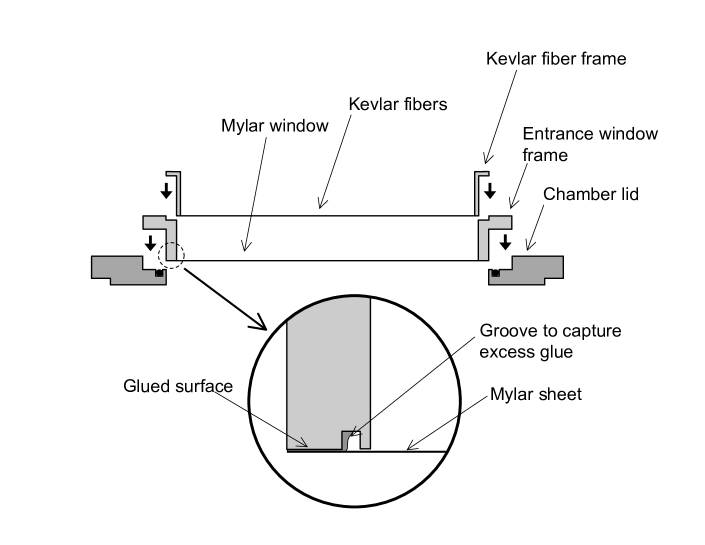
The entrance window is 15 cm in diameter and is made of 6 m thick aluminized Mylar sheet, reinforced by 200 denier Kevlar fiber [18]. The window is glued onto the window frame with Araldite 2011 epoxy, and is then inserted into the opening on the chamber lid. An o-ring provides a seal between the window frame and the chamber lid. The Kevlar fiber is strung with a 5 mm spacing, and is epoxied onto a separate aluminum frame which is inserted into the opening of the window frame (See Fig. 8).
During the developmental tests, we found that it was very important not to let the excess epoxy flow out onto the surface of the Mylar sheet when the window frame is glued on to a Mylar sheet. The epoxy hardened on the surface of the Mylar sheet causes a tear to develop when the window is subject to a pressure difference and needs to bow in or out. Machining a groove on the window frame to capture the excess epoxy (see Fig. 8) substantially improved the longevity of the windows.
Thin Kevlar reinforced Mylar windows are discussed in Ref. [19]. However, our method differs from that in Ref. [19] as follows. In Ref. [19], the window is of a cylindrical shape, and therefore the best performance was obtained when the Kevlar fibers were glued on the surface of Mylar sheet preformed to a cylindrical shape. In our case, the window is glued onto a flat circular frame, and yields to some radius when a pressure difference is applied across the window. If the Kevlar fibers are directly glued on to the surface of the Mylar sheet, it tends to rip the Mylar sheet off as the window bows out under a pressure difference. The best performance was obtained when the Kevlar fibers are only fixed on the frame, allowing them to move against the surface of the Mylar sheet when it bows out under a pressure difference.
The entrance window withstands a pressure difference of up to 200 torr. We chose this configuration as a result of a compromise between the strength (and the leak rate) and the amount of material. For example, 3 m Mylar sheet could not be used because of the high leak rate due to pin holes on the sheet.
The exit window is 15 cm in diameter and is made of 6 m thick aluminized Mylar sheet. Since there is only a small pressure difference ( torr), there is no need for Kevlar reinforcement.
2.8 Gas handling system
The function of the gas handling system is as follows.
-
•
In normal operation, it maintains the MWPC gas pressure at 100 torr within 1%, while flowing gas into the MWPC at a rate of cc/min. It also maintains the pressure in the nitrogen volume to be torr below the MWPC gas pressure.
-
•
During the initial pump-out, it evaculates the MWPC and the nitrogen volume while keeping the pressure difference across the front and back window within the limit given for each window.
-
•
It protects the MWPC windows and the wire planes in case of accidents, including a loss of the SCS vacuum and a power failure.
Figure 9 shows how the constant gas flow and the constant pressure in the MWPC volume and the constant gas pressure in the nitrogen volume are maintained during normal operation (the first item listed above). The mass flow controller (MKS type 1179A) [20] ensures that a constant mass flow of gas enters the MWPC gas volume, while the pressure valve (MKS type 248A) throttles its opening to control the flow of gas that leaves the MWPC gas volume so that the pressure is maintained at the target pressure (100 torr). The pressure of the gas in the MWPC gas volume is measured by a capacitance manometer (MKS Baratron 626 [21]), and the pressure information is used by a controller (MKS type 146C) that controls the pressure valve.
The nitrogen pressure was controlled by a pneumatic relay (Fairchild Model 14212EJ). It uses the control pressure (in this case the MWPC gas pressure) to control the output pressure (in this case the nitrogen pressure). There is a constant flow of nitrogen gas through the input. The excess gas is directed to a vacuum pump.
With this system, we are able to control the MWPC gas to maintain its pressure at 100 torr within 0.5%. The nitrogen pressure in the nitrogen volume is typically maintained at 5 torr below the MWPC gas pressure within a few torr. (We would like to keep the MWPC gas pressure slightly higher than the nitrogen pressure so that the exit window will slightly bow out to keep it from touching the cathode wire plane.)
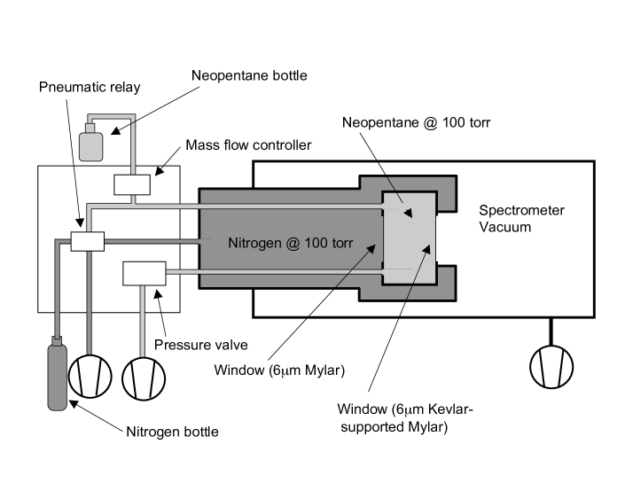
Figure 10 shows the actual gas panel diagram, including valves and pressure switches that allow us to pump out the MWPC volume safely and protect the MWPC windows in case of accidents.

3 Detector performance test and results
Two identical MWPCs were successfully constructed. An off-line detector test was performed using an 55Fe source to study the MWPC response to mono-energetic x rays. The pulse height of the 5.9 keV signal was studied as a function of the bias voltage. A 130-keV electron gun was then used to test the MWPC for its response to an electron beam. Each of these tests are described in detail below.
3.1 Gas property study with an 55Fe source
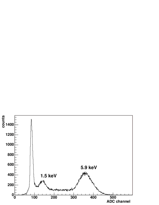
The response of the UCNA MWPC was first studied by irradiating the MWPC by 5.9 keV x rays (Mn K x rays) from an 55Fe source. At this energy, the photon-matter interaction is dominated by the photoelectric effect. Since the average energy deposition of -decay electrons in the MWPC is several keV, the total energy peak of the 5.9 keV x rays provides an almost ideal means to study the performance of the UCNA MWPC.
Because of the technical and administrative difficulties associated with placing the 55Fe source in vacuum, the tests were done using an arrangement as follows. The MWPC front window was replaced with an aluminum plate with a 25.4-mm diameter hole. A window made of 12-m thick Mylar sheet was glued over the hole, and x rays were introduced through this hole.
For comparison, we also performed the same tests with the MWPC filled with 1 atm P10 gas (90% argon, and 10% ethane), which is commonly used as an MWPC gas.
Shown in Fig. 11 is a typical x-ray spectrum with the MWPC filled with 100 torr neopentane gas. In addition to the Mn K x rays at 5.9 keV, we also see the Al K x rays at 1.5 keV, which are generated by Mn K x rays incident on the chamber body which is made of aluminum.
We also measured the pulse height of the amplifier output of the anode signal for 5.9 keV x rays as a function of the bias voltage between the anode and the cathode with the MWPC filled with 100 torr neopentane. For this measurement, the cathode and the entrance and exit windows were kept at the same potential for simple operation. Also, the same measurement was performed with the MWPC filled with 1 atm P10 gas for a comparison. Figure 12 shows the measured pulse height as a function of the bias voltage. As seen from the figure, a reasonable pulse height was obtained with 100 torr neopentane. From a detection efficiency measurement, the nominal operational voltage was chosen to be 2700 V.

In principle, the measured pulse height can be related to the gas multiplication factor as follows.
| (1) |
where is the size of the amplifier output voltage pulse, is the gain of the amplifier which converts a charge pulse to a voltage pulse, is the energy of an x-ray photon, is the amount of energy necessary to create one electron-ion pair in the gas, is the absolute value of the charge of the electron ( C), and is the gas multiplication factor. accounts for the reduction in the pulse height due to the fact that the shaping time of the amplifier is shorter than the time it takes for the pulse to reach its maximum amplitude. For this particular geometry, it is estimated that . With keV and V/pC, and assuming eV for neopentane,111The -value for methane (CH4) is known: eV. The -value is typically eV for most gases. we obtain for the gas multiplication factor at 2700 V.
3.2 Tests with a low energy electron gun
The response of the UCNA MWPC was then studied using the 130 keV Kellogg electron gun. A schematic of the set up for this test is shown in Fig. 13. The Kellogg electron gun was able to provide an electron beam of up to 130 keV and the current could be varied from a few electrons per second to several microamperes. A more detailed description of the Kellogg electron gun can be found in Ref. [22].

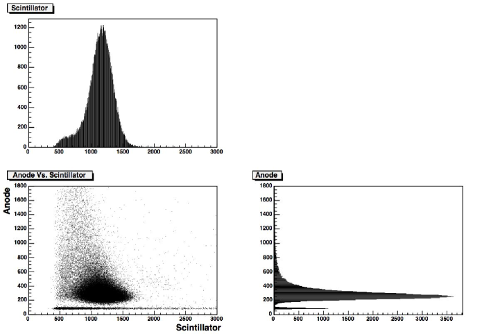
For this test, the electron current from the Kellogg electron gun was adjusted so that the event rate on the MWPC was a few kHz. The trigger was provided by the plastic scintillator located downstream of the MWPC. In Fig. 14, we show pulse height spectra of the anode signal and the scintillator signal.
As discussed in Section 2.6, the hit position for each event was reconstructed by first obtaining the center of gravity of the signals on each cathode plane, and then combining the information from both cathode planes. The top panel of Fig. 15 shows the reconstructed position along the axis perpendicular to the anode wire direction.
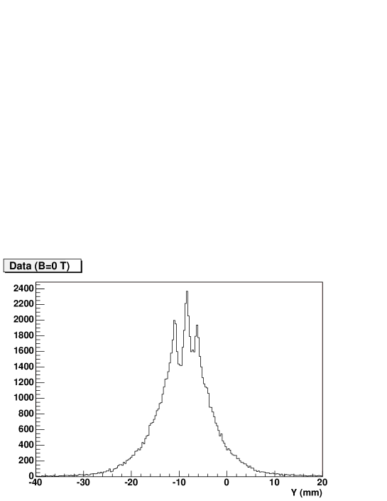
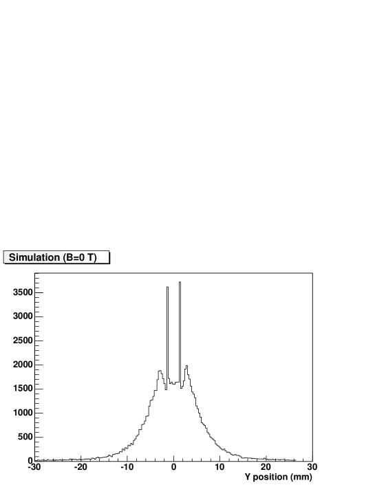
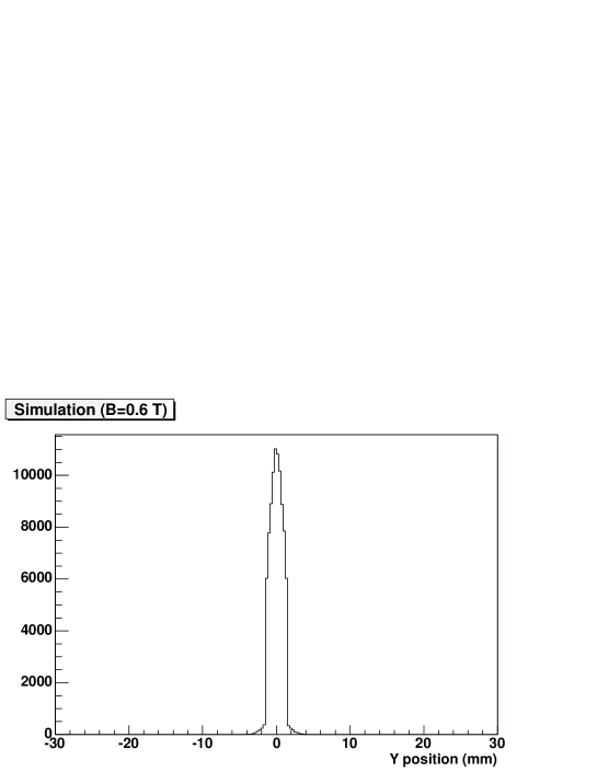
Since there is no strong magnetic field along the direction of the beam (as in the full experiment), the overall position distribution (full width mm) is dominated by multiple scattering in the front window and the MWPC gas. A Monte Carlo simulation was performed and it was confirmed that the observed position distribution is consistent with the simulation (see the middle panel of Fig. 15). In addition to this 15 mm wide distribution, there are narrow spikes. These are due to events in which only one cell222An MWPC is divided into cells, each containing one anode wire at its center. Electric field lines going through any part of a given cell terminate at the same anode wire. received energy deposition. The position of the spikes corresponds to the location of the anode wires around which the avalanche occurred. The continuum below the spikes is due to events where more than one cell received energy deposition. The width of the spikes is mm and is the position resolution of the MWPC in the absence of multiple scattering. This resolution is dominated by electronic noise. This, combined with simulations, indicates that the position of the center of the spiral of each beta particle entering the MWPC can be determined to better than 1.5 mm once the MWPC is put in the 0.6 T magnetic field of the field expansion region of the SCS magnet, which will greatly suppress the multiple scattering effect (see the bottom panel of Fig. 15).
4 Summary
A new multiwire proportional chamber was designed and constructed for precision studies of neutron decay angular correlations. Its design has several novel features, including the use of neopentane as the MWPC gas and the Kevlar supported thin entrance window. Two such MWPCs were successfully constructed. Various off-line tests confirmed that these MWPCs have sufficient sensitivity to low energy particles and allow hit position determination with sufficient position resolution.
5 Acknowledgments
We gratefully acknowledge the technical support of R. Cortez and J. Pendlay. We thank J. Mohnke for his suggestion of using neopentane as the MWPC gas, P. Chan for his help with setting up the wire winding machine, and E. Lin and C. Kessens for their help with the thin window development. We thank D. Snowden-Ifft of Occidental College for generously loaning us his wire winding machine. We thank C. Morris for various valuable suggestions. This work was supported by the National Science Foundation.
References
- [1] H. Abele, et al., Eur. Phys. J. C 33, 1 (2004).
- [2] C. L. Morris, et al., Phys. Rev. Lett. 89, 272501 (2002).
- [3] A. Saunders, et al., Phys. Lett. B593, 55 (2004)
- [4] The UCNA Collaboration, A proposal for an accurate measurement of the neutron spinelectron angular correlation in polarized neutron beta-decay with ultracold neutrons, 2000.
- [5] B. Plaster, et al., in preparation.
- [6] T. Tabata, R. Ito, and S. Okabe, Nucl. Instr. and Meth. 94, 509 (1971).
- [7] D. Lazic, et al., Nucl. Instr. and Meth. A 410, 159 (1998).
- [8] A. Breskin, R. Chechik, and N. Zwang, Nucl. Instr. and Meth. 165, 125 (1979).
- [9] Mylar® is a registered trademark of DuPont Teijin Films.
- [10] Multi Channel Systems, http://www.multichannelsystems.com
- [11] M. Kuze, et al. Jpn. J. Appl. Phys. 26, 1348 (1987).
- [12] D. P. Snowden-Ifft, C. J. Martoff, and J. M. Burwell, Phys. Rev. D 61, 101301(R) (2003).
- [13] PHT Permanent Magnet Clutch/Brake Model PHT-0.05s, Ogura Industrial Corp., http://www.ogura-clutch.com/.
- [14] F. Sauli, CERN Report 77-09 (1977).
- [15] Araldite® is a registered trademark of Huntsman Advanced Materials.
- [16] Dielectric Sciences Inc., 88 Turnpike Rd., Chelmsford, MA 01824-3526.
- [17] CAEN S.p.A. Construzioni Apparecchiature Ellecttroniche Nucleari, http://www.caen.it/.
- [18] Kevlar® is a registered trademark of DuPont.
- [19] L. G. Atencio, C. L. Morris, and C. P. Sadler, Nucl. Instr. and Meth. A 334, 643 (1993).
- [20] MKS Instruments, Inc., http://www.mkinst.com/.
- [21] Baratron® is a registered trademark of MKS Instruments, Inc.
- [22] J. W. Martin et al., Phys. Rev. C 68, 055503 (2203).