Force transmission in a packing of pentagonal particles
Abstract
We perform a detailed analysis of the contact force network in a dense confined packing of pentagonal particles simulated by means of the contact dynamics method. The effect of particle shape is evidenced by comparing the data from pentagon packing and from a packing with identical characteristics except for the circular shape of the particles. A counterintuitive finding of this work is that, under steady shearing, the pentagon packing develops a lower structural anisotropy than the disk packing. We show that this weakness is compensated by a higher force anisotropy, leading to enhanced shear strength of the pentagon packing. We revisit “strong” and “weak” force networks in the pentagon packing, but our simulation data provide also evidence for a large class of “very weak” forces carried mainly by vertex-to-edge contacts. The strong force chains are mostly composed of edge-to-edge contacts with a marked zig-zag aspect and a decreasing exponential probability distribution as in a disk packing.
I Introduction
Among singular features of granular media, force transmission has received particular interest during the last decade. The contact forces in model granular media, as observed by experiments and numerical simulations, are highly inhomogeneous and their probability density functions (pdf’s) are wide Liu et al. (1995); Radjai et al. (1996); Coppersmith et al. (1996); Mueth et al. (1998); Lovol et al. (1999); Bardenhagen et al. (2000); Antony (2001); Majmudar and Behringer (2005); Silbert et al. (2002). The granular texture is generically anisotropic in two respects: 1) The contact normal directions are not random; 2) The force average as a function of contact normal direction is not uniform. The corresponding fabric and force anisotropies in shear are responsible for mechanical strength at the scale of the packing Radjai et al. (1998); Kruyt and Rothenburg (1996); Bathurst and Rothenburg (1988); Rothenburg and Bathurst (1989). Another interesting aspect, first analyzed in Ref. Radjai et al. (1998) is the fact that the forces organize themselves in two distinct classes which contribute differently to fabric anisotropy, shear stress, and dissipation. In particular, the shear stress is fully transmitted via a “strong” contact network, materialized by force “chains”. The stability is ensured by the antagonist role of “weak” contacts which prop strong force chainsRadjai et al. (1998); Staron and Radjai (2005).
The force transmission properties have been for the most part investigated in the case of granular media composed of isometric (circular or spheric) particles. However, in various fields of science and engineering, the grains are seldom so ”perfect”. For example, elongated and platy shapes are encountered in biomaterials or pharmaceutical applications. Such shapes have unequal dimensions and induce thus a degree of anisotropy in the bulk behavior in addition to fabric and force anisotropies Ouadfel and Rothenburg (2001); Antony and Kuhn (2004); Cambou et al. (2004); Nouguier-Lehon et al. (2003). On the other hand, granular geomaterials are often composed of angular particles with plane faces as polyhedra. While rounded particles enhance flowability, angular shape is susceptible to enhance the shear strength, a factor of vital importance to civil-engineering applications Nouguier-Lehon et al. (2003); Alonso-Marroquin and Herrmann (2002); Pena et al. (2006). The railway ballast is a well-known case where particle shape must be optimized to avoid excessive differential settlement under vertical loading Saussine et al. (2006); Markland (1981); Wu and Thompson (2000). In such circumstances, the analysis of force transmission is a key to improve performance.
In dealing with effects of particle shape, the issue is that a general quantitative description of particle morphology requires various shape parameters. For regular polygons in 2D, for instance, the only shape parameter is the number of sides (besides the diameter) whereas for irregular polygons more information is needed about the positions of the vertices in a reference system attached to the particle. In soil mechanics, angularity and roundedness are among basic parameters used to describe particle shapes Mitchell and Soga (2005). As far as force transmission is concerned, at least two parameters seem to be most relevant: 1) shape anisotropy (anisometry), which contributes to the anisotropy of stress transmission Ouadfel and Rothenburg (2001); 2) facettedness, which allows for extended (face to face, edge to face and edge to edge) contacts between particles leading possibly to the formation of columnar structures within a granular assembly.
In this paper, we consider one of the simplest possible shapes, namely regular pentagons. Among regular polygons, the pentagon has the lowest number of sides, corresponding to the least roundedness in this category, without the pathological space-filling properties of triangles and squares. We seek to isolate the effect of edge-to-edge contacts on force transmission by comparing the data with a packing of circular particles that, apart from the particle shape, is identical in all respects (preparation, friction coefficients, particle size distribution) to the pentagon packing. Both packings are subjected to biaxial compression simulated by means of the contact dynamics method. The presence of edge-to-edge contacts affects both quantitatively and qualitatively the microstructure and the overall behavior during shear. These contacts do not transmit torques, but they are able to accommodate force lines that are usually unsustainable in packings of disks.
This paper is organized as follows. We first present in Section II the numerical procedures and a brief technical introduction to the detection and treatment of edge-to-edge contacts in the framework of the contact dynamics method. In Section III, we compare stress-strain and volume-change characteristics. Then, In Sections IV and V, we analyze the texture and force transmission features. In Section VI, we focus on the pentagon packing and we analyze the structure of force networks with vertex-to-edge and edge-to-edge contacts. The main results are summarized and discussed in Section VII.
II Numerical procedures
The simulations were carried out by means of the contact dynamics (CD) method Jean and Moreau (1992); Moreau (2004). The CD method is based on implicit time integration of the equations of motion and a nonsmooth formulation of mutual exclusion and dry friction between particles. This method requires no elastic repulsive potential and no smoothing of the Coulomb friction law for the determination of forces. For this reason, the simulations can be performed with large time steps compared to molecular dynamics simulations. We used the platform LMGC90 which is a multipurpose software developed in Montpellier, capable of modeling a collection of deformable or undeformable particles of various shapes Dubois and Jean (2003).
II.1 Contact dynamics for polygons
The particles are rigid polygons exerting normal and shear forces, and , respectively, on each other. We attribute a positive sign to compressive normal forces. The relative normal velocity between two particles in contact is counted positive when they move away from each other. Then, the condition of geometrical contact between two particles is expressed by the following mutually exclusive alternatives:
| (1) |
In the same way, the Coulomb friction law involves three mutually exclusive conditions:
| (2) |
where is the sliding velocity at the contact and is the friction coefficient. The unknown variables are particle velocities and contact forces. These are calculated at each time step by taking into account the conservation of momenta, the constraints expressed by (1) and (2), and the dissipation of kinetic energy during inelastic collisions between particles (ref). We use an iterative research algorithm based on a nonlinear Gauss-Seidel scheme. The uniqueness is not guaranteed for perfectly rigid particles in absolute terms. However, by initializing each step of calculation with the forces calculated in the preceding step, the set of admissible solutions shrinks to fluctuations which are basically below the numerical solution. Let us note that in molecular dynamics simulations, this “force history” is encoded by construction in the particle positions.
The research algorithm is applied to a set of potential contacts, identified or updated in each step. The contact detection between two bodies consists in looking for the overlaps of the portions of space they occupy. The treatment of the mechanical interaction requires additionally the identification of a common tangent plane (a line in 2D). Of course, contact may take place through a larger contact zone than a single point. Several algorithms exist for overlap determination between convex polygons Dubois and Jean (2003); Saussine et al. (2006). In 2D simulations of the present paper, the detection of contact between two convex polygonal bodies was implemented through the so-called ”shadow overlap method” devised by Moreau Dubois and Jean (2003); Saussine et al. (2006), with reliability and robustness tested in several years of previous applications to various states of granular materials Nouguier-Lehon et al. (2003); Cholet et al. (2003); Azéma et al. (2006).
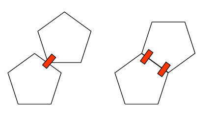
In detection of contacts between two polygons, two situations arise: 1) If a single corner is found crossing an edge of the partner polygon, the direction of this edge is viewed as the tangent direction. By orthogonally projecting the intruding vertex onto the edge, one determines the penetration depth, while the nominal contact point is chosen at the center of this distance. Below, we will refer to this vertex-to-edge contact as “simple” contact. 2) In case of double intrusion, the common tangent line is fixed from as a mean between the two overlapping edges and a segment of this line is identified as the contact segment. The impenetrability between two particles at such an edge-to-edge contact is ensured by applying the contact laws (1) and (2) to only two points of the contact segment (Fig. 1). For this reason, we refer below to edge-to-edge contacts as “double” contacts. In practice, two forces are calculated at each double contact, but only their resultant and application point are material. In this respect, the choice of the two points representing a double contact does not affect the dynamics of the system.
II.2 Numerical samples
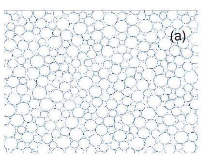
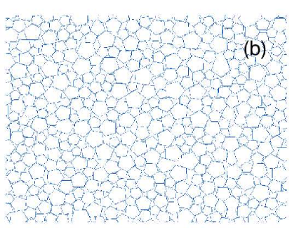
We generated two numerical samples. The first sample, denoted S1, is composed of 14400 regular pentagons of three different diameters: of diameter cm, of diameter cm and of diameter cm. The second sample, denoted S2, is composed of 10000 discs with the same polydispersity. Both samples were prepared according to the same protocol. A dense packing was first constructed following simple geometrical rules Taboada et al. (2005) and then compressed isotropically under a constant stress Pa applied onto the right and top walls. The gravity was set to zero in order to avoid force gradients in the samples. The coefficient of friction was set to 0.4 between grains and to 0 with the walls. At equilibrium, both numerical samples were in isotropic stress state. The solid fraction was for S1 and for S2. The aspect ratio was , where and are the height and width of the sample, respectively. Figure 2 displays snapshots of the two packings at the end of isotropic compaction.
The isotropic samples were subjected to vertical compression by downward displacement of the top wall at a constant velocity of cm/s for a constant confining stress acting on the lateral walls. The simulations were run up to a total cumulative vertical strain of with a time step of s. The CPU time was s and s per particle and per time step on a G5 Apple computer. Since we are interested in quasistatic behavior, the shear rate should be such that the kinetic energy supplied by shearing is negligible compared to the static pressure. This can be formulated in terms of an ”inertia parameter” GDR-MiDi (2004) defined by
| (3) |
where is the strain rate, is the total mass, and is the average pressure. The quasistatic limit is characterized by the condition . In our biaxial simulations, was below .
III Strength and dilatancy
In this section, we compare the stress-strain and volume-change behavior between the packings of polygons (sample S1) and disks (sample S2). For the calculation of the stress tensor, we consider the ”tensorial moment” of each particle i defined by Moreau (1997); Staron and Radjai (2005):
| (4) |
where is the component of the force exerted on particle i at the contact c, is the component of the position vector of the same contact c, and the summation is runs over all contacts c of neighboring particles with the particle i (noted briefly by ). It can be shown that the tensorial moment of a collection of rigid particles is the sum of the tensorial moments of individual particles. The stress tensor for a packing of volume is simply given by Moreau (1997); Staron and Radjai (2005):
| (5) |
where is the intercenter vector joining the centers of the two touching particles at the contact . Remark that the first summation runs over all particles whereas the second summation involves all contacts in the volume , with each contact appearing only once. We extract the mean stress , and the stress deviator , where and are the principal stresses. The major principal direction during vertical compression is vertical.
The strain parameters are the cumulative vertical, horizontal and volumetric strains , and , respectively. By definition, we have
| (6) |
where is the initial height and is the total downward displacement, and
| (7) |
where is the initial volume and is the cumulative volume change.
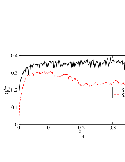
Figure 3 shows the normalized shear stress for the samples S1 and S2 as a function of shear strain . For S2, we observe a classical behavior characterized by a hardening behavior followed by (slight) softening and a stress plateau corresponding to the residual state of soil mechanics Mitchell and Soga (2005). For S1, we observe no marked stress peak. The residual stress is higher for polygons () than for disks (). This means that the polygon packing has a higher angle of internal friction defined by
| (8) |
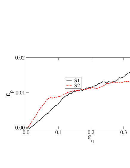
Figure 4 displays the cumulative volumetric strain for polygons and disks as a function of . Both samples dilate and tend to isochoric deformation at large strains. It is remarkable that the polygon packing S1 initially dilates less than the disk packing S2. This behavior is reversed at larger strains with a crossover occurring after the peak state. Notice that the solid fraction is initially lower in S1 () than in S2 (). This is because it is more difficult to obtain a compact packing with polygonal shapes by isotropic compression as a result of enhanced steric effects compared to disks. In other words, angular particles can form larger pores compared to rounded particles. The volumetric deformation can also be expressed in terms of the so-called ”dilatancy angle” defined by Wood (1990)
| (9) |
The cumulative angle of dilatancy, i.e. during shear up to the residual state, is only slightly higher for the polygon packing than the disk packing.
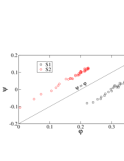
The plot of as a function of , i.e. the so-called stress-dilatancy diagram, is shown in Fig. 5 for polygons and disks Wood (1990). Remarkably, both plots are parallel to the line with an offset :
| (10) |
The offset is the friction angle at zero dilatancy. We have for disks and for polygons. This observation is in agreement with the arguments of Taylor Wood (1990); Radjai and Roux (2004) based on energy balance and recently revisited also in the case of cohesive granular media Taboada et al. (2006). The higher level of for the polygon packing reflects the organization of the microstructure and the features of force transmission for each particle shape. This point is considered in more detail in the following section.
IV Granular texture
The granular texture, i.e. the organization of the particles and their contacts in space, is basically controlled by steric exclusions between the particles and force balance conditions Troadec et al. (2002). The texture can be described in terms of various statistical descriptors pertaining to the force-bearing network of particles. At the lowest order, the compactness of the structure can be described in terms of both the solid fraction and the coordination number . The connectivity of the network can further be characterized by the fraction of particles having exactly contact neighbors. These are scalar parameters or functions. At higher orders, the anisotropy of the texture is described by different “fabric tensors”. We consider here these geometrical descriptors in order to identify the signature of particle shape.
IV.1 Connectivity
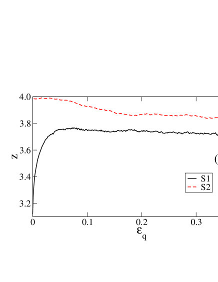
The connectivity of the particles by force-bearing contacts is described at the lowest order by the average number of contact neighbors per particle. The particles with no force-bearing contact are thus removed from the statistics. Note also that each double (edge-to-edge) contact for the polygons is counted once although double contacts are treated as two point contacts belonging to the contact segment (see section II). Fig. 6a displays the evolution of for the pentagon packing (S1) and the disk packing (S2) as a function of . The coordination number evolves to a steady-state value in both samples that is higher for S2 () than for S1 (). The difference is, however, much less important than in the initial configuration ( for S2 compared to for S1) prepared by means of isotropic compaction.
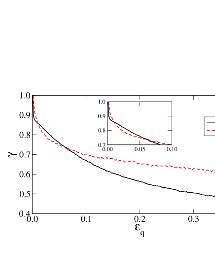
It is also interesting to compare the two samples in terms of “contact lifetimes”. Let us consider a reference configuration, e.g. the initial state of each sample. We follow the history of each contact listed in this state. In particular, we define as the fraction of persistent contacts of the initial list. During deformation, declines from to as an increasing number of initial contacts are lost due to particle rearrangements. Fig. 6b shows as a function of for S1 and S2. We see that, following a rapid initial falloff, decreases slowly in both samples but the rate of contact loss is globally higher for polygons than disks. We remark that even at , the contact list is renewed by only .
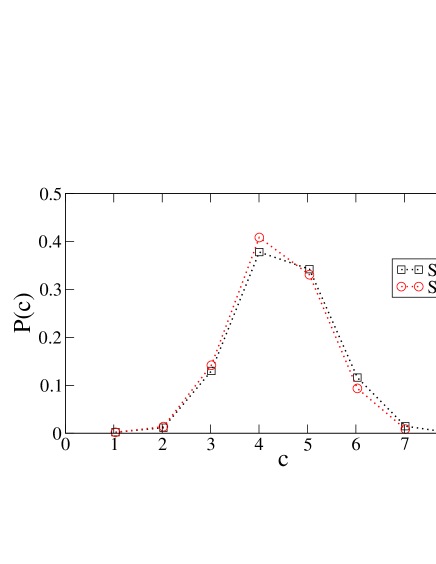
The connectivity of the particles is plotted in Fig. 7 for S1 and S2 at . Interestingly, the two plots are nearly identical with a peak for . In both samples, the fraction of particles with 5 contacts is larger than that with 3 contacts. This shows that the connectivity does not reflect the difference in texture between the two packings although a qualitative difference exists as we shall see below by considering fabric anisotropy and force transmission.
IV.2 Fabric anisotropy
The shear strength of dry granular materials is generally attributed to the buildup of an anisotropic structure during shear due to friction between the particles and as a result of steric effects depending on particle shape Oda et al. (1980); Cambou (1993); Radjai et al. (2004). Several methods have been used to quantify the fabric (structural) anisotropy of granular materials Satake (1982); Rothenburg and Bathurst (1989); Oda and Iwashita (1999). A common approach is to consider the probability distribution of the contact normals which are generically nonuniform. In two dimensions, the unit vector is described by a single angle , the orientation of the contact normal. The probability density function of contact normals provides a detailed statistical information about the fabric. It is -periodic in the absence of an intrinsic polarity for .
Most structural information is generally condensed in the second moment of , called fabric tensor Satake (1982):
| (11) |
where and design the components in a reference frame and is the total number of contacts in the control volume . By definition, . The anisotropy of the contact network is given the difference between the principal values and . We define the fabric anisotropy by
| (12) |
For fix coordinates, with the x-axis pointing along , we define also a ”signed anisotropy” by
| (13) |
where is the major principal direction of the fabric tensor. For , we have . The signed anisotropy corresponds to the second term of the Fourier expansion of and it is useful whenever the direction of anisotropy is not constant.
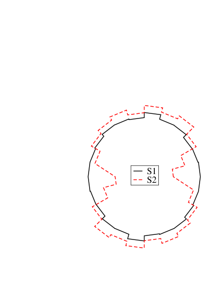
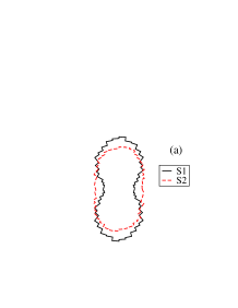
Figure 8 displays a polar representation of for the samples S1 and S2 at . We observe a nearly isotropic distribution for the pentagon packing in spite of shearing whereas the disk packing is markedly anisotropic. This is a surprising observation in view of the higher shear strength of the pentagon packing (Fig. 3). It is also counterintuitive as one expects that double contacts should allow a polygon packing to build more easily an anisotropic structure.
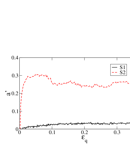
The evolution of is shown in Fig. 9 as a function of for S1 and S2. The privileged direction of the contacts, corresponding to , is vertical in both packings. In both cases, increases from 0 (as a result of the initial isotropic compression) to its largest value in the residual state. The anisotropy stays quite weak in the pentagon packing whereas the disk packing is marked by a much larger anisotropy, increasing to and then relaxing to a slightly lower value in the residual state. As we shall see below, the low anisotropy of the pentagon packing results from a particular organization of the force network in correlation with the orientations of simple and double contacts in the packing (section VI). We will also show that the large shear strength of the pentagon packing is a consequence of a strong force anisotropy in this packing (see next section).
V Force transmission
In this section, we analyze the anisotropy and inhomogeneity of force networks in the packings of pentagons and disks. This leads us to consider the contributions of force and texture anisotropies to average shear stresses.
V.1 Force anisotropy
The angular distribution of contact forces in a granular packing can be represented by the average force as a function of the contact normal direction . We distinguish the average normal force from the average tangential force formally defined by Rothenburg and Bathurst (1989)
| (14) |
where and are the normal and tangential forces, respectively, acting at the contact (according to a sign convention attributing positive values to the normal forces), is the set of contacts with direction for angle increments , and is the number of contacts in .
By definition, the two functions and are -periodic. After sufficiently long monotonous shearing, these functions can be approximated by their Fourier expansions truncated beyond the second term Rothenburg and Bathurst (1989); Radjai et al. (2004):
| (15) |
where is the average force, and represent the anisotropies of the normal and tangential forces, respectively, and and are their privileged directions.
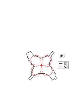
In Fig. 10, the functions and are displayed in polar coordinates at . The pentagon and disk packings show pronounced force anisotropy with a stronger anisotropy in the case of pentagons both for normal and tangential forces. These plots can be fitted by harmonic functions [Eq. (15)] in order to estimate the force anisotropies and . However, it is more convenient to estimate the anisotropies through the following “force tensors”:
| (16) |
It is easy to see that , and by identification with (15) we have
| (17) |
where the subscripts and refer to the principal values of the tensors.
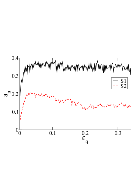
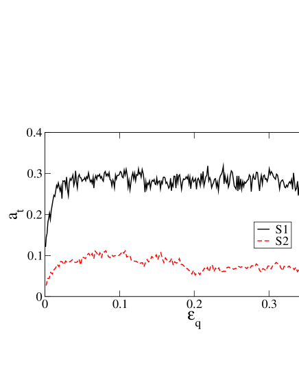
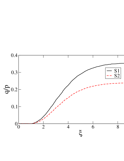
Figure 11 shows the evolution of and with in samples S1 and S2. We see that, in contrast to fabric anisotropies (Fig. 9), the force anisotropies in pentagon packing remain always above those in the disk packing. This means that the aptitude of the pentagon packing to develop large force anisotropy and strong force chains is not solely dependent on the global fabric anisotropy of the system. In section VI, we will show that the force anisotropy of the pentagon packing stems from the high anisotropy of the sub-network of double contacts and strong activation of friction forces. Indeed, due to the geometry of the pentagons, i.e. the absence of parallel sides, the strong force chains are mostly of zig-zag shape, as observed in Fig. 13b, and the stability of such structures requires strong activation of tangential forces. This explains, in turn, the large value of for pentagons, very close to , whereas in the disk packing is nearly half of .
The anisotropies , and are interesting descriptors of granular microstructure and force transmission as they underlie the shear stress. Indeed, it can be shown that the general expression of the stress tensor Eq. (5) leads to the following simple relation Rothenburg and Bathurst (1989); Radjai et al. (2004):
| (18) |
where the cross products between the anisotropies have been neglected and it has been assumed that the stress tensor is coaxial with the fabric tensor Eq. (11) and the force tensors Eq. (16). Fig. 12 shows that Eq. (18) holds quite well both for pentagons and disks.
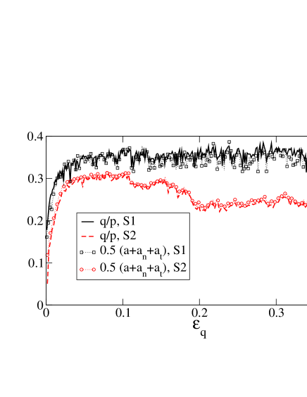
A remarkable consequence of Eq. (18) is to reveal the distinct origins of shear stress in pentagon and disk packings. The fabric anisotropy provides a major contribution to shear stress in the disk packing (Fig. 9) whereas the force anisotropies are more important for shear stress in the pentagon packing (Fig. 11). In this way, in spite of the weak fabric anisotropy , the larger force anisotropies and allow the pentagon packing to reach higher levels of compared to the disk packing.
V.2 Force distributions
The strong inhomogeneity of contact forces is a well-known feature of granular media. It has been investigated mostly for spherical or cylindrical particles both by experiments and numerical simulations Antony (2001); Liu et al. (1995); Majmudar and Behringer (2005); Mueth et al. (1998); Radjai et al. (1996); Lovol et al. (1999); Silbert et al. (2002); Bardenhagen et al. (2000). The probability density function (pdf) of normal forces is characterized by two features which seem to be specific to granular media: 1) The pdf is roughly a decreasing exponential function for forces above the mean, 2) In the range of weak forces below the mean, the pdf does not decline to zero with the force. The relative scatter of data reported by different authors for weak forces shows the sensitivity of the pdf in this range to the details of the microstructure. But, the common observation that there is a large number of contacts transmitting very weak forces, is a straightforward signature of the arching effect. From this point of view, one expects that angular particle shape will influence mainly the distribution of weak forces by enhancing the arching effect.
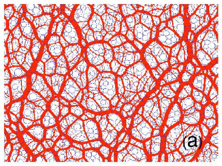
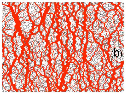
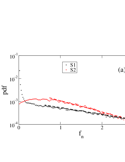
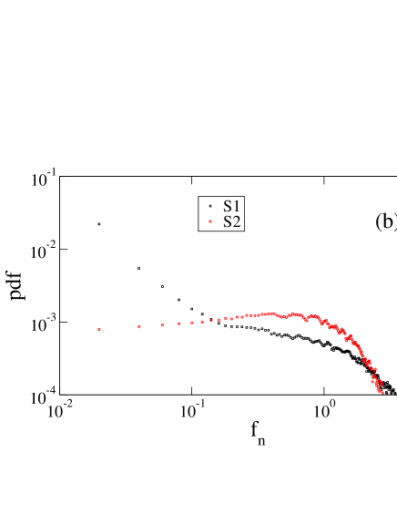
Figure 13 displays maps of normal forces in a portion of each of the samples S1 and S2 at a large cumulative strain. We observe the strong anisotropy of normal forces in the pentagon packing compared to the disk packing (as discussed in section V) as well as the zig-zag form of the strong force chains. The normal force pdf’s are shown in Fig. 14 in log-linear and log-log scales at large strains. The forces are normalized by the mean normal force in each sample. In both samples, the number of strong forces (above the mean ) falls off exponentially:
| (19) |
with and . The smaller value of means that the distribution is wider for pentagons compared to disks. The distribution is nearly uniform in the whole range of weak forces () in S2. In the pentagon packing S1, we observe a uniform distribution only in the range . Nearly of forces are in this range. The number of “very weak” forces in S1 in the range increases faster than a power law as tends to zero. A fraction of contacts belong to this range. The presence of numerous “very weak” forces in the pentagon packing is a clear signature of enhanced arching effect that can be characterized, as we shall see below, by the respective roles of simple and double contacts with respect to force transmission.
V.3 Bimodal character of stress transmission
The genuine organization of contact forces in granular media, involving strong force chains propped by weak forces, was first analyzed by Radjai et al. by means of contact dynamics simulations for packings of circular and spherical particles Radjai et al. (1998). This analysis proceeds by considering the subset of contacts which carry a force below a cutoff force normalized by the mean force. This subset is referred to as the “-network”. The variation of a quantity evaluated for the “-network” as is varied from to the maximal force in the system, provides its correlation with the contact force. Here, we apply this same approach to S1 and S2 samples for the stress ratio , defined as stress deviator (normalized by the total pressure of the sample) in the -network, and for , defined as the fabric anisotropy in the -network.
The plot of is shown in Fig. 15 for S1 and S2 in the residual state. In both samples, the stress deviator is nearly zero for , i.e. for the normal forces below the average force. This means that the shear stress is almost totally sustained by the “strong” contact network for the pentagon packing as well as for the disk packing. Fig. 16 shows the fabric anisotropy as a function of in the samples S1 and S2. By definition, a positive value of corresponds to the principal stress direction whereas a negative value corresponds to the orthogonal direction. We see that the direction of anisotropy is orthogonal to the principal stress direction () for weak forces (small ). This “orthogonal” anisotropy of the weak forces is more important in the pentagon packing compared to the disk packing, and, as shown in the inset to Fig. 16, it is mainly due to “very weak” forces. When is increased beyond , becomes less negative and finally changes sign, showing that the strong contacts are preferentially parallel to the principal axis. These strong contacts are less than 40% of all contacts, but their positive contribution to overcompensates the negative contribution weak contacts. For large , the partial anisotropy approaches the fabric anisotropy of the whole system.
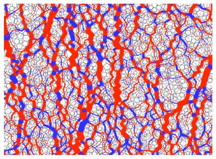
These data demonstrate the bimodal character of stress transmission also in the pentagon packing in spite of a very different particle geometry. The mean force plays a particular role in differentiating strong contacts from weak contacts. However, the force pdf’s (Fig. 14) and the anisotropy of weak forces (Fig. 16) provide also evidence for the existence of a class of very weak forces, corresponding approximately to the range , within the weak network. This class is strongly anisotropic with a privileged direction which is orthogonal to the major principal stress direction, and the corresponding force pdf diverges as the force tends to zero. Fig. 17 displays a tricolor map of the contact network representing very weak, intermediate () and strong contacts in the pentagon packing. Large cells of strong contacts are composed of zig-zag chains. The anisotropy of strong contacts is reflected in the elongated shape of these cells along the major principal stress direction. Both intermediate and very weak forces prop these cells.
VI Simple versus double contacts
In this section, we focus on the organization of simple and double contacts in the pentagon packing. The double contacts, i.e. the side-sharing polygons, are generally assumed to be at the source of the higher strength of polygon packings. For the texture, we would like also to investigate the proportions of simple and double contacts and their respective contributions to the overall anisotropy of the pentagon packing. It is also important to identify the role of double contacts in force transmission.
The general expression [Eq. 5] of the stress tensor allows us to perform a unique additive decomposition of the stress into two parts:
| (20) |
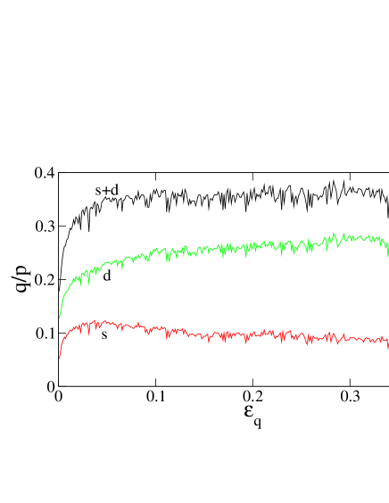
where is obtained from the expression (5) by restricting the summation to simple contacts, and is the complementary tensor involving only double contacts. The respective stress deviators and normalized by the mean stress are shown in Fig. 18 as a function of strain . The strength of double contacts varies from two to three times that of simple contacts during shear deformation of the pentagon packing. The proportions and of simple and double contacts are shown in Fig. 19 as a function of . The same figure displays the relative force averages and , where and are the mean normal forces of simple and double contacts, respectively. We see that increases with strain but remains below . On the other hand, initially we have , reflecting the isotropic state of the packing prepared by isotropic compaction. However, increases with shear up to in the residual state. This means that the larger shear stress carried by double contacts in the residual state is due to the larger mean normal force of double contacts despite their smaller proportion in the packing.
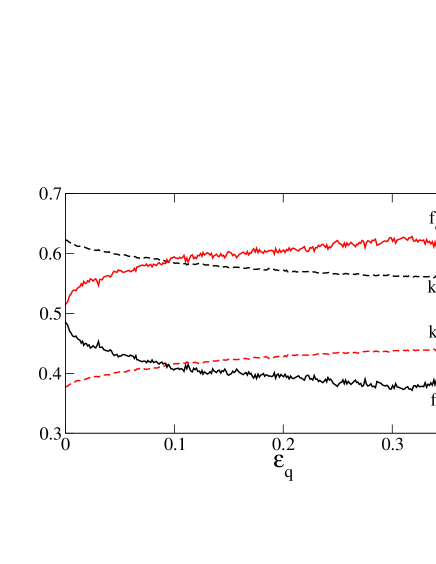
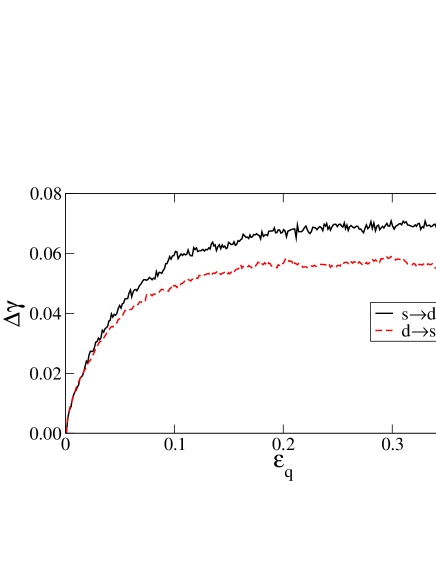
The growth of the number of double contacts shown in Fig. 19 represents the gradual consolidation of the sample. In Fig. 20 we plot the cumulative proportions and of simple contacts turning to double and vice versa, respectively. Although transformation between the two contact types occurs at each step in both directions and , the consolidation involves on average a net fraction of simple contacts transforming into double contacts.
The connectivity of the pentagon packing by simple and double contacts can be represented by the proportion of particles with exactly simple contacts and double contacts. Fig. 21 shows a grey level map of this function for the pentagon packing in the residual state. The row corresponds to particles with only simple contacts (nearly of the total number of particles) whereas the column represents the particles with only double contacts (nearly ). On average, a particle has more simple contacts than double contacts but the maximum occurs at .

We now consider the fabric tensor decomposed in a similar way as the stress tensor [Eq. (20)] into two partial tensors:
| (21) |
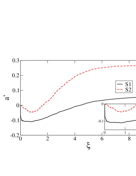
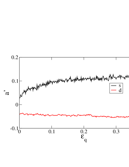
where and are defined as in Eq. (11) by simply restricting the summation to simple and double contacts, respectively, and by dividing the sum by the total number of contacts. The respective anisotropies and of simple and double contacts are displayed in Fig. 22 as a function of . The interesting observation here is that the simple contacts have a negative anisotropy which, according to Eq. (13), means that simple contacts are mostly oriented perpendicular to the major principal fabric direction . In other words, most simple contacts belong to the weak network. In contrast, the double contacts have an increasing positive anisotropy which is larger than the mean anisotropy of the sample. This is consistent with the fact that the double contacts take over larger forces and they contribute more to the shear stress than simple contacts.
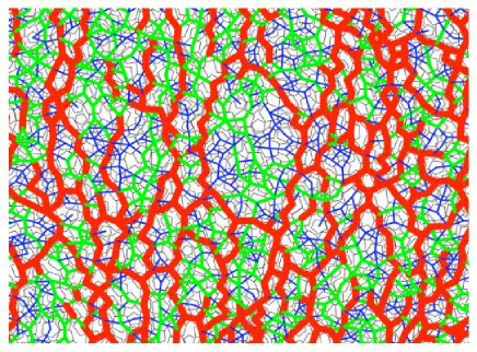
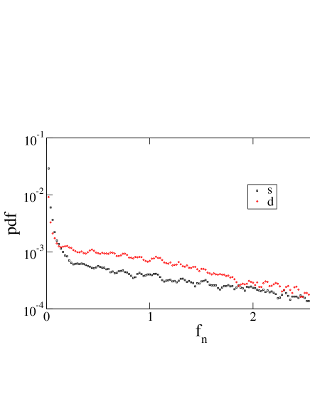
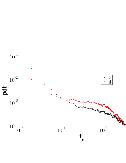
The normal force pdf’s for simple and double contacts are shown in Fig. 23. Both contact types are involved in weak and strong networks and the pdf’s have the same functional form. But the contribution of simple contacts is more important in the range of very weak forces. Once again, as for anisotropy, the very weak contacts appear to be related to the particular geometry of the pentagons. At large strains, about of all contacts belong to the very weak force network with simple contacts against double contacts. A snapshot of the normal force network is shown in Fig. 24 where the line widths are proportional to the line width with different colors (or grey levels) for simple and double contacts. The remarkable feature of this map is the network of very strong zigzag force chains composed mostly of double contacts and occasionally mediated by simple contacts.
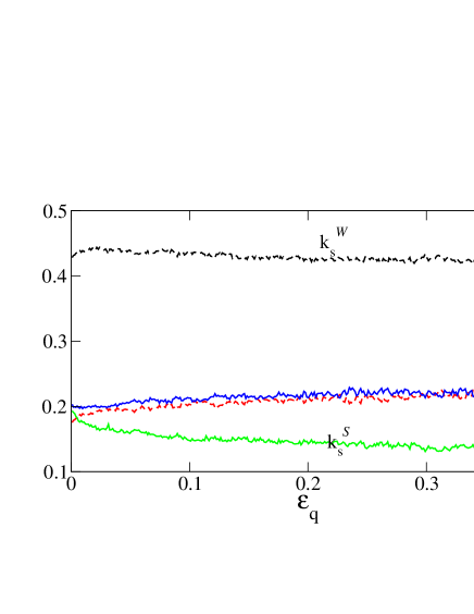
The proportions and of strong (S) and weak (W) simple (s) contacts, respectively, as well as the proportions and of strong and weak double (d) contacts are plotted in Fig. 25 as a function of . We see that in the strong network () the proportion of double contacts is nearly the same as the proportion of simple contacts in the initial (isotropic) state, but during shear declines down to in the residual state, in agreement with the impression left by Fig. 24. We have an inverse situation for the weak network composed of two times more simple contacts than double contacts, i.e. in the residual state. It is also interesting to remark that the fraction of weak contacts, i.e. in the residual state is very close to that () in the case of the disk packing.
VII Conclusion
The objective of this paper was to isolate the effect of particle shape on force transmission in granular media by means a detailed comparison between two similar packings with different particle shapes: pentagons vs. disks. We observed enhanced shear strength and force inhomogeneity in the pentagon packing. But, unexpectedly, the pentagon packing was found to develop a lower structural (fabric) anisotropy compared to the disk packing under shear. This low fabric anisotropy, however, does not prevent the pentagon packing from building up a strong force anisotropy that underlies its enhanced shear strength compared to the disk packing.
This finding is interesting as it shows unambiguously that the force anisotropy in a granular material has two distinct sources: (1) Fabric anisotropy, with a maximum value depending on particle shapes; (2) Particle shapes. The first mechanism is crucial for the disk packing so that the force anisotropy, and the shear stress as a result, vanishes in an isotropic disk packing (e.g. when the friction coefficient is set to zero). The second mechanism may be the predominant source of strength for “facetted” particles that can give rise edge-to-edge (in 2D) or face-to-face (in 3D) contacts allowing for strong force localization along such contacts in the packing. Since the fabric anisotropy is low in a pentagon packing, the role of force anisotropy and thus the local equilibrium structures or arching are important with respect to its overall strength properties. The pentagons analyzed in this work provide thus the first counter-example of a system where the role of fabric anisotropy in shear strength is marginal.
Another shape-related effect was the observation of zig-zag force chains mostly composed of edge-to-edge contacts in steady shearing. The vertex-to-edge contacts belong thus mainly to the weak force network or a class of “very weak” forces that can be considered as a signature of enhanced arching or screening effect of forces in the presence of edge-to-edge chains. These “very weak” forces can also be observed, though to a lesser extent, in a disk packing with high coefficients of friction Silbert et al. (2002) or on experimental pdf’s of normal forces acting on the walls of a container Mueth et al. (1998). Let us recall that a “very weak phase” was also evidenced by considering the correlation between friction mobilization and the anisotropy of granular texture in a disk packing at the stability limit Staron and Radjai (2005).
By focusing on pentagon packings, we were able to demonstrate the nontrivial phenomenology resulting from the specific shape of particles as compared to a disk packing. Although general features of force transmission (pdf’s, bimodal character, etc) seem to be robust, the details of force transmission (relative importance of force and fabric anisotropy, the role of edge-to-edge contacts, etc) seem to be strongly shape-dependent. Currently, we work to elucidate this issue for regular polygons (hexagons and higher number of sides) as well as polyhedral particles in three dimensions.
We warmly thank Fréderic Dubois for assistance with the LMGC90 platform used for the simulations. This work was funded by the French Railway Society, the SNCF, and the Région Languedoc-Roussillon of France.
References
- Antony (2001) S. J. Antony, Phys Rev E 63, 011302 (2001).
- Coppersmith et al. (1996) S. N. Coppersmith, C. Liu, S. Majumdar, O. Narayan, and T. A. Witten, Phys. Rev. E 53, 4673 (1996).
- Liu et al. (1995) C. Liu, S. R. Nagel, D. A. Schecter, S. N. Coppersmith, S. Majumdar, O. Narayan, and T. A. Witten, Science 269, 513 (1995).
- Majmudar and Behringer (2005) T. S. Majmudar and R. P. Behringer, Nature 435, 1079 (2005).
- Mueth et al. (1998) D. M. Mueth, H. M. Jaeger, and S. R. Nagel, Phys. Rev. E. 57, 3164 (1998).
- Radjai et al. (1996) F. Radjai, M. Jean, J. Moreau, and S. Roux, Phys. Rev. Letter 77, 274 (1996).
- Lovol et al. (1999) G. Lovol, K. Maloy, and E. Flekkoy, Phys. Rev. E 60, 5872 (1999).
- Silbert et al. (2002) L. E. Silbert, G. S. Grest, and J. W. Landry, Phys. Rev. E 66, 1 (2002).
- Bardenhagen et al. (2000) S. G. Bardenhagen, J. U. Brackbill, and D. Sulsky, Phys. Rev. E 62, 3882 (2000).
- Radjai et al. (1998) F. Radjai, D. E. Wolf, M. Jean, and J. Moreau, Phys. Rev. Letter 80, 61 (1998).
- Kruyt and Rothenburg (1996) N. P. Kruyt and L. Rothenburg, ASME Journal of Applied Mechanics 118, 706 (1996).
- Bathurst and Rothenburg (1988) R. J. Bathurst and L. Rothenburg, J. Appl. Mech. 55, 17 (1988).
- Rothenburg and Bathurst (1989) L. Rothenburg and R. J. Bathurst, Geotechnique 39, 601 (1989).
- Staron and Radjai (2005) L. Staron and F. Radjai, Phys. Rev. E 72, 1 (2005).
- Ouadfel and Rothenburg (2001) H. Ouadfel and L. Rothenburg, Mechanics of Materials 33, 201 (2001).
- Antony and Kuhn (2004) S. J. Antony and M. R. Kuhn, International Journal of Solids and Structures 41, 5863 (2004).
- Cambou et al. (2004) B. Cambou, P. Dubujet, and C. Nouguier-Lehon, Mechanics of Materials 36, 1185 (2004).
- Nouguier-Lehon et al. (2003) C. Nouguier-Lehon, B. Cambou, and E. Vincens, Int. J. Numer. Anal. Meth. Geomech 27, 1207 (2003).
- Alonso-Marroquin and Herrmann (2002) F. Alonso-Marroquin and H. J. Herrmann, Phys. Rev. E 66, 021301 (2002).
- Pena et al. (2006) A. Pena, R. Garcia-Rojo, and H. Herrmann, Granular Matter In Press (2006).
- Saussine et al. (2006) G. Saussine, C. Cholet, P. Gautier, F. Dubois, C. Bohatier, and J. Moreau, Comput. Methods Appl. Mech. Eng. 195, 2841 (2006).
- Markland (1981) J. M. E. Markland, Geotechnique 31, 3,367 (1981).
- Wu and Thompson (2000) Wu and Thompson, J Acoust Soc Am 108, 1046 (2000).
- Mitchell and Soga (2005) J. Mitchell and K. Soga, Fundamentals of Soil Behavior (Wiley, NY, 2005).
- Jean and Moreau (1992) M. Jean and J. J. Moreau, in Proceedings of Contact Mechanics International Symposium (Presses Polytechniques et Universitaires Romandes, Lausanne, Switzerland, 1992), pp. 31–48.
- Moreau (2004) J. Moreau, in Novel approaches in civil engineering, edited by M. Frémond and F. Maceri (Springer-Verlag, 2004), no. 14 in Lecture Notes in Applied and Computational Mechanics, pp. 1–46.
- Dubois and Jean (2003) F. Dubois and M. Jean, in Actes du sixième colloque national en calcul des structures - CSMA-AFM-LMS - (2003), vol. 1, pp. 111–118.
- Cholet et al. (2003) C. Cholet, G. Saussine, P. Gautier, F. Dubois, C. Bohatier, G. Combe, and K. Sab, in World Congress on Railway Research (WCRR) (2003).
- Azéma et al. (2006) E. Azéma, F. Radjai, R. Peyroux, F. Dubois, and G. Saussine, Phys. Rev. E 74, 031302 (2006).
- Taboada et al. (2005) A. Taboada, K. J. Chang, F. Radjai, and F. Bouchette, Journal Of Geophysical Research 110, 1 (2005).
- GDR-MiDi (2004) GDR-MiDi, Eur. Phys. J. E 14, 341 (2004).
- Moreau (1997) J. J. Moreau, in Friction, Arching, Contact Dynamics, edited by D. E. Wolf and P. Grassberger (World Scientific, Singapore, 1997), pp. 233–247.
- Wood (1990) D. Wood, Soil behaviour and critical state soil mechanics (Cambridge University Press, Cambridge, England, 1990).
- Radjai and Roux (2004) F. Radjai and S. Roux, in The Physics of Granular Media, edited by H. Hinrichsen and D. E. Wolf (Wiley-VCH, Weinheim, 2004), pp. 165–186.
- Taboada et al. (2006) A. Taboada, N. Estrada, and F. Radjai, Phys. Rev. Lett. 97, 098302 (2006).
- Troadec et al. (2002) H. Troadec, F. Radjai, S. Roux, and J.-C. Charmet, Phys. Rev. E 66, 041305 (2002).
- Oda et al. (1980) M. Oda, J. Koshini, and S. Nemat-Nasser, Geotechnique 30, 479 (1980).
- Cambou (1993) B. Cambou, in Powders and Grains 93, edited by C. Thornton (A. A. Balkema, Amsterdam, 1993), pp. 73–86.
- Radjai et al. (2004) F. Radjai, H. Troadec, and S. Roux, in Granular Materials: Fundamentals and Applications, edited by S. Antony, W. Hoyle, and Y. Ding (RS.C, Cambridge, 2004), pp. 157–184.
- Satake (1982) M. Satake, in Proceedings of the IUTAM symposium on deformation and failure of granular materials, Delft, edited by P. A. Vermeer and H. J. Luger (A. A. Balkema, Amsterdam, 1982), pp. 63–68.
- Oda and Iwashita (1999) M. Oda and K. Iwashita, eds., Mechanics of Granular Materials (A. A. Balkema, Rotterdam, 1999).