Guiding, focusing, and sensing on the sub-wavelength scale using metallic wire arrays
Abstract
We show that two-dimensional arrays of thin metallic wires can guide transverse electromagnetic (TEM) waves and focus them to the spatial dimensions much smaller that the vacuum wavelength. This guiding property is retained for the tapered wire bundles which can be used as multi-channel TEM endoscopes: they capture a detailed electromagnetic field profile created by deeply sub-wavelength features of the studied sample and magnify it for observation. The resulting imaging method is superior to the conventional scanning microscopy because of the parallel nature of the image acquisition by multiple metal wires. Possible applications include terahertz and mid-infrared endoscopy with nanoscale resolution.
Diffraction of light is the major obstacle to a variety of applications requiring concentrating optical energy in a small spatial volume: light cannot be confined to dimensions much smaller than half of its wavelength . Applications that would benefit from overcoming the diffraction limit include nonlinear spectroscopy and harmonics generation Kneip et al. (1997); Michaels et al. (2000); Ichimura et al. (2004); Cheng et al. (2001), sub-wavelength optical waveguiding P.Berini (2001); Bozhevolnyi et al. (2006); Dionne et al. (2006), and nanofabrication Shao and Chen (2005). Utilizing plasmonic materials with a negative dielectric permittivity circumvents diffraction limit because interfaces between polaritonic () and dielectric () materials support surface plasmons that can be confined to sub- dimensions. Examples of diffraction-beating devices based on plasmonics include superlenses Pendry (2000); Fang et al. (2005); Melville and Blaikie (2005); Taubner et al. (2005), coupled-sphere waveguides Maier et al. (2001), and sharp focusing tips Stockman (2004).
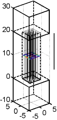
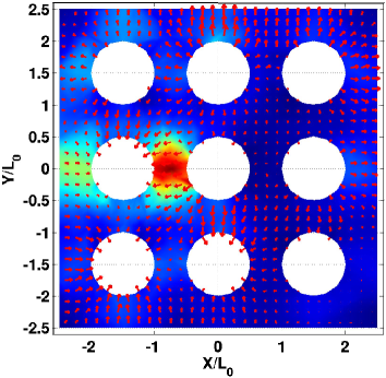
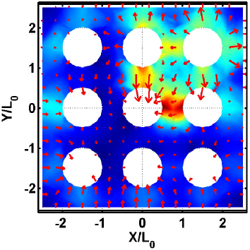
High losses associated with surface plasmonics are hampering many of these applications. Another challenge yet to be met is designing practical imaging modalities based on sub- plasmons that convert near-field electromagnetic (EM) perturbations into the far field where they can be easily observed. In this Letter we propose a solution to these two problems: a tapered multi-wire array supporting sub-wavelength transverse electromagnetic (TEM) waves. Examples of the multi-wire endoscopes based on such arrays (un-tapered and tapered) are shown in Fig. 1. We have demonstrated that the tapered endoscope can accomplish two tasks: (i) creating near the base of an endoscope a magnified image of deeply sub-wavelength objects (metal spheres, in our case) placed at the endoscope’s tip [see Fig. 3(a)], and (ii) creating near the tip of an endoscope a de-magnified image of a mask placed at the endoscope’s base [see Fig. 3(b)]. Accomplishing the first task is necessary for making a sub- sensor while accomplishing the second one – for making a sub- lithographic tool.
Single metallic wires and coaxial wire cones have recently attracted considerable attention as low-loss waveguides Keilmann (1995); Wang and Mittelman (2004) of TEM-like modes of THz and far-infrared radiation. Using a single wire waveguide has its limitations: for example, if a wire is used as a high spatial resolution sensor, then only a single bit of information can be collected without scanning the wire. We demonstrate that a bundle of closely spaced wires can act as a multi-channel sensor capable of simultaneously collecting information from a spatially distributed object. Electromagnetic properties of metallic wire arrays has been previously investigated in the context of metamaterials Pendry et al. (1996); Sarychev et al. (2000); Belov et al. (2003); Shapiro et al. (2006). Below we review the electromagnetic properties of an infinite square array with period of straight (along the -direction) metallic wires of an arbitrary shape in the plane. Two well-known types of EM waves with the propagation wavenumber and frequency characterized by the scalar potentials and are supported: (i) transverse magnetic (TM) modes with , , and (ii) transverse electric (TE) modes with , , and . Here and satisfy the following differential equation: . In addition to , these waves are characterized by the transverse Bloch wavenumber , where satisfies the phase-shifted boundary conditions: and . At the perfect metal surface and are also satisfied. Dispersion relations , where labels the propagation band (the Brillouin zone) can be readily computed numerically for both types of waves.
The lesser known wave type is the TEM eigenmode of the periodic metal cylinder array with a very simple dispersion relation: . (If the medium between the wires has a dielectric permittivity , then ). TEM waves have no longitudinal electric or magnetic fields, and are characterized by a single scalar potential satisfying the phase-shifted periodic boundary conditions and at the metal surface. Electric and magnetic field of the TEM wave are orthogonal to each other and given by and . As will be shown below, the remarkable property of the TEM waves of being dispersionless with respect to the transverse wavenumber can be explored in sub-wavelength guiding/imaging applications. One can, therefore, view TEM modes as being transversely local: the image of an object with finite transverse size does not spread out as it is transported along the endoscope. To understand why the propagation wavenumber of TEM modes is degenerate in , consider a finite array of wires surrounded by a perfectly conducting metal shell. Finite extent of the array discretizes so that there are distinct wavenumbers supported by the array. This is in agreement with the well known fact Carbonini (1992) that the vector space of TEM potentials of a multiconnected coaxial waveguide has the dimension equal to the number of inner conductors. Therefore, TEM modes of an endoscope consisting an wire bundle are capable of transferring channels of information along its length.
An ideal endoscope transfers an arbitrary image of the field distribution at over a significant distance to with minimal distortion. Indeed, any field distribution at with an arbitrary spatial detail size can be expanded as the sum of TE, TM, and TEM modes with the Bloch wavenumbers and the Brillouin zone index , and propagated with their corresponding propagation constants , where correspond to TEM, TE, and TM modes, respectively. However, if the total crossection of the tapered endoscope becomes smaller than , then all TE and TM modes are evanescent, i. e. for . The only modes that can transport the image without distortion are the TEM modes. Because they do not form a complete set, they can only ensure spatial resolution of order the wire spacing . Therefore, imaging with TEM waves is a form of discrete sampling: the exact spatial profile of a small scatterer with a spatial dimension will not be resolved in the image, but its presence in a specific unit cell will be detected. Because TEM modes have no cutoff, making the spacing extremely sub-wavelength results in an arbitrary high spatial resolution.
To demonstrate how a metal wire endoscope can transport a deeply sub-wavelength image, we have numerically simulated the following problem: transferring an image of a metallic sphere with a diameter using a array of conducting wires encased in a square sub-wavelength metal waveguide. Wire spacing and diameter are and , endoscope’s length is . All simulations in this Letter are made under a simplifying assumption of perfectly electrically conducting (PEC) metals. As shown at the end of the Letter, this assumption is valid for EM waves spanning mid-IR and THz frequency ranges. PEC boundary conditions make the results scalable to any wavelength. Therefore, all dimensions are scaled to an arbitrary length scale . Dielectric permittivity of the surrounding medium was assumed to be . The schematic of the endoscope is shown in Fig. 1(left). The EM wave is launched from a single-mode square waveguide at . We have chosen a circularly polarized incident wave to avoid polarization sensitivity of a square array of wires. The scattering metal sphere’s center is at , , . Two lateral sphere positions have been simulated: (a) , and (b) . The respective intensity distributions of the at the end of the endoscope () shown in Figs. 2(a,b) confirm the earlier made statement about the sampling nature of TEM-based imaging: only the mere presence of a scattering sphere inside a given elementary cell is detected, with the details of the scatterer’s shape lost. Nevertheless, the spatial resolution equal to the size of the unit cell is clearly established by this simulation. The peak intensity in the imaging plane is higher by one order of magnitude when the scattering object is present compared with the case of a multi-wire endoscope with no scattering object: . The latter intensity is another five orders of magnitude higher than when the wires are removed from the waveguide: .
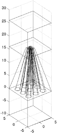
Next, we demonstrate that an endoscope based on a tapered metal wire array shown in Fig. 1(right) is capable of magnification and demagnification. One obvious application of image magnification is a sensor collecting EM fields from highly sub-wavelength objects in the immediate proximity of the endoscope’s tip and transforming them into a much larger detectable image. Image demagnification can be applied to surface pattering and lithography: a complex large mask can be placed close to the wide base of the endoscope and projected/focused towards the tip creating a highly sub-wavelength intensity distribution in the tip’s vicinity. We’ve simulated a pyramid-shaped metallized fiber threaded by a array of metallic wires. Endoscope’s base has a square crossection (where, as before, ), wires separation is , wires’ diameters are . All these dimensions are proportionately scaled down by a factor at the tip. The purpose of this simulation is to illustrate image magnification and demagnification by a factor . As in the non-tapered case, the tapered endoscope is terminated on both ends by a single-mode () metallic waveguide. A practical multi-channel endoscope will have a much larger (e. g., ) number of metal wires.
For magnification demonstration, a small metallic sphere with diameter is placed at a distance above the endoscope’s tip half-way between the central wire and the next one on the left. The sphere is illuminated from the top by a circularly polarized electromagnetic wave. The image of taken at (slightly above the endoscope’s base) is shown in Fig. 3(a). The sphere’s image (or that of any strong scatterer) magnified by a factor appears as an enhanced field in the image plane. The following intensity contrasts are found: and .
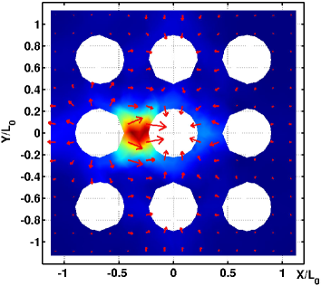
The opposite process (de-magnification, or image focusing) can also be demonstrated using the same tapered endoscope. A metallic sphere with the diameter is placed at a distance below the endoscope’s base half-way between the central wire and the next one on the left. The image located in the plane of the tip (hot spot shown in Fig. 3(b)) is spatially compressed by a factor . Despite the fact that the electromagnetic wave propagates through a very narrow waveguide, field intensity in the hot spot is about the same as that of the incident wave. Had the coupling efficiency of the incident wave into TEM waves been close to unity, one would expect an intensity increase by a factor due to the narrowing of the endoscope’s area. That this is not happening is attributed to the low coupling efficiency because of the sub-wavelength size of the scattering sphere. Nevertheless, this simulation illustrates that extremely sub-wavelength intensity landscapes can be created near the tip of a tapered nanowire array. The following intensity contrasts are found: and .
All simulations presented in this Letter were performed using the PEC assumption. This assumption is highly accurate in the far-infrared and THz frequency ranges. It is, however, instructive to check whether the concept of a multi-wire endoscope could be potentially extended to mid-infrared wavelengths. Below we demonstrate that electromagnetic modes of an array of plasmonic wires closely resembling TEM modes of an array of PEC wires do exist. These surface plasmon polariton (SPP) modes possess two essential properties enabling them to guide, focus, and perform local sensing on a nanoscale: (a) they are low loss, and (b) they are essentially dispersionless in the transsverse direction, i. e. , where . Let’s consider because of the importance of this wavelength to chemical sensing Brehm et al. (2006) as well the availability of low-loss silica fibers. We have used a commercial finite elements code COMSOL to compute the propagation constants of such SPPs assuming a square array of gold wires (, , ) embedded in a silica fiber with . An endoscope based on this wire array provides spatial resolution. For the center of the Brillouin zone it was found that confirming low loss of the TEM-like SPPs. Very weak dispersion of on of the SPPs was confirmed by calculating at the edge of the Brillouin zone: .
The validity of the ideal TEM description is justified for transport distances of . Ohmic losses over distances reduce the transmitted light intensity but do not necessarily deteriorate the spatial resolution () of the image. Transverse dispersion, however, reduces spatial resolution below for . For higher spatial resolutions, however, transverse dispersion become more severe than Ohmic losses: an endoscope must be shorter than if the spatial resolution of is desired. We conclude from these results that, although the classic dispersion relation for TEM waves is no longer strictly satisfied for plasmonic wires, the TEM-like SPPs are sufficiently low-loss and dispersionless that the performance of the un-tapered and tapered multi-wire endoscopes described in this Letter are barely affected. The actual fabrication of tapered silica fibers threaded by metallic wires can proceed according to the recently developed Sazio et al. (2006)high pressure chemical vapor deposition technique.
In conclusion, we have demonstrated the possibility of a novel deeply sub-wavelength multi-channel endoscope based on an array of metallic wires. The device is based on the remarkable propagation properties of the transverse electromagnetic (TEM) waves: their lack of the cutoff and transverse dispersion. Such endoscopes may find a variety of applications in the areas of infrared imaging, guiding, and focusing. This work is supported by the ARO MURI W911NF-04-01-0203 and the AFOSR MURI FA9550-06-1-0279.
References
- Kneip et al. (1997) K. Kneip, Y. Wang, H. Kneip, L. T. Perelman, I. Itzkan, R. R. Dasari, and M. S. Feld, Phys. Rev. Lett. 78, 1667 (1997).
- Michaels et al. (2000) A. M. Michaels, J. Jiang, and L. Brus, J. Phys. Chem. B 104, 11965 (2000).
- Ichimura et al. (2004) T. Ichimura, N. Hayazawa, M. Hashimoto, Y. Inouye, and S. Kawata, Phys. Rev. Lett. 92, 220801 (2004).
- Cheng et al. (2001) J.-X. Cheng, L. D. Book, and X. S. Xie, Opt. Lett. 26, 1341 (2001).
- P.Berini (2001) P.Berini, Phys. Rev.B 63, 125417 (2001).
- Bozhevolnyi et al. (2006) S. I. Bozhevolnyi, V. S. Volkov, E. Devaux, J.-Y. Laluet, and T. W. Ebbesen, Nature 440, 508 (2006).
- Dionne et al. (2006) J. A. Dionne, H. J. Lezec, and H. A. Atwater, Nano Letters 6, 1928 (2006).
- Shao and Chen (2005) D. B. Shao and S. C. Chen, Appl. Phys. Lett. 86, 253107 (2005).
- Pendry (2000) J. B. Pendry, Phys. Rev. Lett. 85, 3966 (2000).
- Fang et al. (2005) N. Fang, H. Lee, C. Sun, and X. Zhang, Science 308, 534 (2005).
- Melville and Blaikie (2005) D. O. S. Melville and R. J. Blaikie, Optics Express 13, 2127 (2005).
- Taubner et al. (2005) T. Taubner, D. Korobkin, Y. Urzhumov, G. Shvets, and R. Hillenbrand, Science 313, 1595 (2006).
- Maier et al. (2001) S. A. Maier, M. Brongersma, and H. Atwater, Appl. Phys. Lett. 78, 16 (2001).
- Stockman (2004) M. I. Stockman, Phys. Rev. Lett. 93, 137404 (2004).
- Wang and Mittelman (2004) K. Wang and D. M. Mittelman, Nature 432, 376 (2004).
- Keilmann (1995) F. Keilmann, Infrared Phys. Technol. 36, 217 (1995).
- Pendry et al. (1996) J. B. Pendry, A. J. Holden, W. J. Stewart, and I. Youngs, Phys. Rev. Lett. 76, 4773 (1996).
- Belov et al. (2003) P. A. Belov, R. Marques, S. I. Maslovski, I. S. Nefedov, M. Silveirinha, C. R. Simovski, and S. A. Tretyakov, Phys. Rev. B 67, 113103 (2003).
- Shapiro et al. (2006) M. A. Shapiro, G. Shvets, J. R. Sirigiri, and R. J. Temkin, Opt. Lett. 31, 2051 (2006).
- Sarychev et al. (2000) A. K. Sarychev, R. C. McPhedran, and V. M. Shalaev, Phys. Rev. B 62, 8531 (2000).
- Carbonini (1992) L. Carbonini, lEEE Trans. Micr. Theory and Tech. 40, 665 (1992).
- Brehm et al. (2006) M. Brehm, T. Taubner, R. Hillenbrand, and F. Keilmann, Nano Letters 6, 1307 (2006).
- Sazio et al. (2006) P. J. A. Sazio et al., Science 311, 1583 (2006).