Optical Coherence Spectro-Tomography by all-Optical Depth-Wavelength analysis
L. Froehly, M. Ouadour, L. Furfaro, P. Sandoz, T. Gharbi
Département d’Optique PM Duffieux, Institut FEMTO-ST, UMR CNRS , Université de Franche-Comté, Besançon Cedex, France
P. Leproux, G. Huss, V. Couderc
XLIM - UMR CNRS 6172, 123,avenue Albert Thomas, 87060 Limoges Cedex, France
Abstract
Current spectroscopic optical coherence tomography (OCT) methods rely on a posteriori numerical calculation. We present an alternative for accessing optically the spectroscopic information in OCT, i.e. without any post-processing, by using a grating based correlation and a wavelength demultiplexing system. Conventional A-scan and spectrally resolved A-scan are directly recorded on the image sensor. Furthermore, due to the grating based system, no correlation scan is necessary. In the frame of this paper we present the principle of the system as well as first experimental results.
OCIS codes: 050.0050, 070.0070, 110.4500, 120.0120, 120.3180, 170.4500
For a decade the interest for Optical Coherence Tomography (OCT) has been growing in the field of biomedical imaging. Main reasons are the non destructive character of these methods, the image resolution down to the micrometer scale either in-depth or in-plane and the capability to perform optically in vivo non-destructive biopsies. Tomographic images can be obtained by different OCT configurations which are classified in two main families: Time-Domain OCT (TD-OCT) and Fourier Domain OCT (FD-OCT)[2].
For a few years a new trend is to complement the reconstruction of in-depth 3D tissue structure by functional information as a help in medical diagnosis. In this way solutions that supply indications on the actual biological metabolism of the inspected tissues were reported; for instance: polarization OCT imaging[3], spectroscopic OCT[4] or CARS-OCT[5]. Our work associates also a functional signature to in-depth OCT microstructure reconstructions. We propose an all-optical device for the spectro-tomographic characterization of the inspected tissues. We access optically to a spectro-tomogram characterizing the depth-wavelength behavior of a sample line (). This spectro-tomogram corresponds to an usual A-scan that is spectrally-resolved on a continuous set of spectral bands. The width of the latter is determined by the setting of the experimental set-up. Furthermore this spectro-tomogram is obtained without any scanning since the depth exploration is performed by a temporal correlator based on a static diffraction grating.
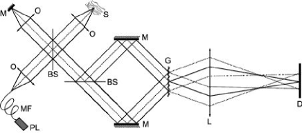
The experimental set-up used is composed of three main parts as depicted in Fig. 1. Firstly the sample information is encoded via a Linnik interferometer. The latter is illuminated with a supercontinuum of light issued from a microstructured optical fiber pumped by a Q-switched Nd-YAG laser[6]. Since this low coherence light source has a transversally singlemode emission, the sample is illuminated only along the axial point spread function of the microscope objective used (therefore the OCT information finally obtained with depth-wavelength resolution corresponds also to this sample volume). Secondly the light beams issued from the Linnik interferometer are directed toward a second interferometer. In this Mach-Zehnder-like interferometer the output beamsplitter is replaced by a transmission diffraction grating disposed in the perpendicular direction. Because of the incident angles of the two beams, the transverse direction of the diffraction grating introduces a time-delay varying linearly between the recombined beams. The sample depth is thus encoded across the grating that forms a time correlation axis. The inherent principle of that kind of temporal correlator was first introduced in [7] for spectroscopy. In 1991 it has been applied to intermodal dispersion measurements in optical fibers[8]. More recently some adaptations of this set-up were proposed for optical tomography[9, 10, 11, 1]. A key property of that configuration is to reduce significantly the carrier frequency of the interference fringes. This effect can be explained by the change of the average propagating direction of the interfering wavefronts after diffraction in the order. The third part of the set-up is a simple imaging system that forms the image of the diffraction grating on a two-dimensional CCD image sensor. Then the lines of the CCD camera encode the depth of the sample and a A-scan is displayed without scanning along the image lines (since all the light incident on the diffraction grating is issued from the same sample line, the different lines of the recorded image carry the same depth information). The cascade of the two interferometers should result in autocorrelation. In practise, interfering beams are cross-polarized in both interferometers thanks to polarization multiplexing (quarter and half waveplates are not represented in Fig. 1 for the sake of clarity). Thus we perform intercorrelation instead of autocorrelation and the detected signal can be expressed as:
| (1) |
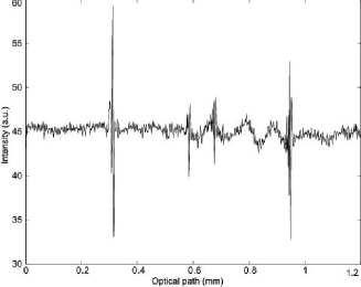
where x is the horizontal coordinate on the CCD camera lines, I the background intensity, designs the real part, and are the spectral distributions of the reference and sample beams respectively, is the incidence angle on the diffraction grating, is the grating period and is the imaging system magnification. The grating effect appears in the term that introduces the fringe frequency change. (The reference beam is assumed to be real while can be either real or complex depending on the optical sample properties). Fig. 2 presents the intensity distribution along an image line as recorded for the inspection of a homemade sample. The latter is made of a 2% Gifrer Eosine solution layered by capillarity between two microscope coverslips. The four interfaces (air-glass; glass-solution; solution-glass, glass-air) are clearly visible and the thickness of both the coverslip and the eosine solution can be retrieved from this intensity distribution after depth calibration. Those data could be used for spectroscopic analysis as obtained classically by numerical windowed Fourier Transform. The light source spectrum extends from to . In this experiment an effective bandwidth of centered around is chosen and selected through the size of the imaging lens. This bandwidth should results in a full depth resolution of about . In practice,mainly due to sample dispersion, it is clear on Fig. 2 that the resolution is lower ().
At this stage of the set-up description, the device constitutes a Linear TD-OCT system in a configuration different from anterior works[9, 10, 11, 12] .
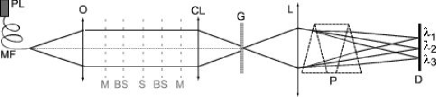
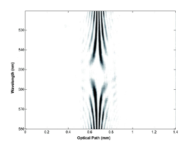
Complementary elements are necessary for the obtention of a spectro-tomogram. These optical elements affect the light propagation only along the vertical direction and appear in Fig. 3, that presents a side view of the set-up. The key-element is the prism that changes the output imaging system into a spectroscope. Then the vertical direction of the CCD camera becomes a spectral axis. The spectroscope resolution is tuned through the position of the cylindrical lenses inserted in the Mach-Zehnder arms and that focus the light beams incident on the grating in a horizontal line, whose height controls the spectral resolution. In this complete system configuration each image line is associated to a particular wavelength and is illuminated by a restricted bandwidth. Therefore each image line provides a spectrally-resolved A-scan and the whole image forms a spectro-tomogram. Fig. 4 presents the recorded spectro-tomograph as a mirror is used as sample. In that case we obtain a signal related to the light source autocorrelation since the sample beam is not modified. The spectral resolution is corresponding to a depth resolution of (given by the relation ). In this result each line corresponds to the autocorrelation of a bandwidth centered around the corresponding wavelength. The progressive variation of the fringe period is due to the wavelength dependence of the diffracted angle. For , the interfering beams are collinear after diffraction and no fringes are visible. The spectro-tomographic information can be expressed as:
| (2) |
where y is the vertical coordinate on the CCD camera and is the spectroscope response for the line y.
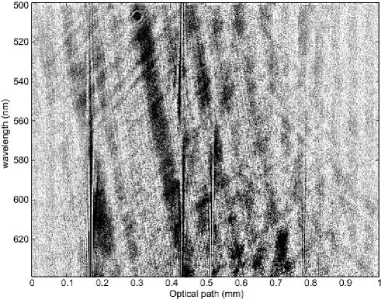
The inspection of the eosine sample resulted in Fig. 5. In this case the spectral resolution was fixed to , leading to a depth resolution of . We observe that the four sample interfaces are visible only in the lower part of the figure, i.e. outside the absorption band of eosine[13]. Wavelengths corresponding to the upper part of the figure are absorbed by the solution and no light returns from the last interfaces that are no more detectable. This spectral information is obtained optically and instantaneously. It complements the reconstruction of the in-depth microstructure of the sample. This result demonstrates clearly the depth-wavelength capabilities of the proposed method for optical coherence spectro-tomography. The lateral resolution is determined by the objective used(5X, N.A.=0.1)and was measured to be (USAF pattern).
At this stage of system development, signal to noise ratio (SNR) measurements would not be significant of the ultimate method capabilities since detection elements are not optimized yet. However one may notice already the following points. Our detection scheme differs from TD-OCT one’s while reconstructed A-scans are quite similar. In one hand no scanning is required and the integration time on the detector can be much longer. On the other hand dynamics and noise performances of image sensors are usually worse than those of photodiodes or PMTs. Finally our detection is closer to FD-OCT one’s since each A-scan information is contained on one CCD line.
A clear interest of an all optical processing system appears for the spectroscopic analysis of OCT responses. In that case, the spectral resolution and the spectral bandwidth of interest are actually determined by the optical components of the device. This point is an advantage over post-processing techniques such as windowed Fourier transforms which are constrained by digital sampling and discretization parameters. Furthermore spectro-tomograms obtained optically are available instantaneously and that point can be important for applications in which a high measurement rate is required. The main drawback of our grating based correlation system is the DC part which decreases the dynamic range available for signal detection. This problem could be solved using a particular kind of CMOS detection already used in parallel TD-OCT[14]. This detector allows both heterodyne detection and DC filtering in real-time. The next step of our work will be to demonstrate the feasibility of the implementation of this kind of detection with our system and the influence of this on the system performances (SNR, sensitivity and dynamic range available for signal detection).
Acknowledgements: We acknowledge the French ANR for funding this work (ANR-05-JCJC-0187-01).
References
- [1] L. Froehly, M. Ouadour, G. Petitjean, L. Furfaro, P. Sandoz, T. Gharbi, P. Leproux, G. Huss, V. Couderc, SPIE proc. 6191,61910N (2006)
- [2] A.F. Fercher, W. Drexler, C. K. Hitzenberger, T. Lasser, Rep. Prog. Phys. 66, 239-303 (2003)
- [3] M.R. Hee, D. Huang, E. A. Swanson, J. G. Fujimoto, JOSA B. 9, 903-908 (1992)
- [4] W. Watanabe, K. Itoh, Opt. Rev. 7, 406-414 (2000)
- [5] C. Vinegoni, J.S. Bredfeldt, D.L. Marks and co (2003-12-18) oai:arXiv.org:physics/0312114
- [6] V. Tombelaine, C. Lesvigne, P. Leproux, L. Grossard, V. Couderc, J.L. Auguste, J.M. Blondy, G. Huss, and P.H. Pioger, Opt. Express 13, 7399-7404 (2005)
- [7] P. Connes - J. of Mod. Opt. 4, 136 - 144 (1957)
- [8] G. Brun, I. Verrier, A. Barthelemy, C. Froehly, J.P. Goure, J. of Opt. Comm. 13, 134 - 139 (1992)
- [9] I. Verrier, G. Brun, J.P. Goure, Appl. Opt. 36, 6225-6230 (1997)
- [10] I. Zeylikovich, R. Alfano, Opt. Com. 135, 217-222 (1997)
- [11] K. Ben Houcine, M. Jacquot, I. Verrier, G. Brun and C. Veillas, Opt. Lett. 29, 2908 (2004)
- [12] C. Hauger, M. Wörz, T. Hellmuth, Appl. Opt. 42, 3896-3902 (2003)
- [13] A. Tamburello Luca, PhD Thesis, Étude des interfaces liquides par génération de deuxième harmonique, 1583, EPFL, Switzerland, 150-151, (1996)
- [14] M. Laubscher, M. Ducros, B. Karamata, T. Lasser, R.P. Salathe, Opt. Express 10, 429-435 (2002)