Thermocapillary valve for droplet production and sorting
Abstract
Droplets are natural candidates for use as microfluidic reactors, if active control of their formation and transport can be achieved. We show here that localized heating from a laser can block the motion of a water-oil interface, acting as a microfluidic valve for two-phase flows. A theoretical model is developed to explain the forces acting on a drop due to thermocapillary flow, predicting a scaling law which favors miniaturization. Finally, we show how the laser forcing can be applied to sorting drops, thus demonstrating how it may be integrated in complex droplet microfluidic systems.
pacs:
47.61.-k, 47.55.dmMicrofluidic droplets have been proposed as microreactors with the aim to provide high performance tools for biochemistry. Individual drops may be viewed as containing one digital bit of information and the manipulation of a large number of slightly differing drops would allow the testing of a large library of genes rapidly and with a small total quantity of material Miller et al. (2006). In microchannels, drops are produced and transported using a carrier fluid Thorsen et al. (2001) and typical channel sizes allow the manipulation of volumes in the picoliter range. Surfactant in the carrier fluid prevents cross-contamination of the drops through wall contact or fusion Song et al. (2003); Joanicot and Ajdari (2005). However, while the geometry of the microchannel may be used to determine the evolution of drops and their contents Song et al. (2003); Joanicot and Ajdari (2005); Link et al. (2004), the implementation of real lab-on-a-chip devices hinges on the active control of drop formation and its evolution, which remains elusive.
In this letter, we remedy the situation by demonstrating experimentally how a focused laser can provide precise control over droplets through the generation of a thermocapillary flow. In doing so, we develop the first theoretical model of a droplet subjected to localized heating, yielding a general understanding of the forces acting on the drop and a scaling law which favors miniaturization. A carrier fluid is still used for the formation and transport of drops but the effects of geometry are augmented with a local thermal gradient produced by the laser beam, focused through a microscope objective inside the microchannel.
Indeed, moving drops with heat has been a preoccupation of fluid mechanicians since the initial work of Young et al Young et al. (1959). Although originally motivated by microgravity conditions where surface effects are dominant Young et al. (1959); Balasubramaniam and Subramanian (2000), microfluidics has opened up a new area where bulk phenomena are negligible compared to surface effects. Recently, thermal manipulation of drops or thin films resting on a solid substrate has received the attention of the microfluidics community either through the embedding of electrodes in the solid Sammarco and Burns (1999); Darhuber et al. (2003) or through optical techniques Garnier et al. (2003); Sur et al. (2004); Kotz et al. (2004). However, the physical mechanisms in the transmission of forces when the liquid touches a solid wall are fundamentally different from the case of drops suspended in a carrier fluid, away from the boundaries Lajeunesse and Homsy (2003). The latter case has received little attention despite the advantages that microchannels offer over open geometries.
Our experimental setup consists of a microchannel fabricated using soft lithography techniques Duffy et al. (1998). Water and oil (Hexadecane + 2% w/w Span 80, a surfactant) are pumped into the channel at constant flowrates, and , using glass syringes and syringe pumps. Channel widths are in the range m and the height is in the range m. Local heating is produced by a continuous Argon-Ion laser (wavelength in vacuum nm), in the TEM00 mode, focused inside the channel through a or microscope objective to a beam waist or m, respectively. The optical approach can be reconfigured in real-time and it allows the manipulation inside small microchannels with no special micro-fabrication. The absorption of the laser radiation by the aqueous phase is induced by adding 0.1% w/w of fluorescein in the water.
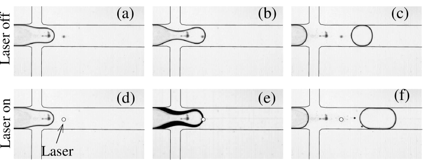
A surprising effect is observed when the water-oil interface reaches the laser spot: In the cross-shaped microchannel of Fig. 1, we produce water drops in oil through the hydrodynamic focusing technique in which two oil flows pinch off water droplets at the intersection of the channels. In the absence of the laser, drops of water are produced in a steady fashion and are transported along with the oil down the drain channel, as shown in Figs. 1(a)-(c). When the laser is illuminated, however, the oil-water interface is blocked in place as soon as it crosses the beam. While the typical drop pinching time is ms in the absence of the laser, we find that we can block the interface for a time which may be of several seconds, as shown in Figs. 1(d)-(f) (see supporting video 1). During the time , the drop shedding is completely inhibited and the volume in the water tip increases until the viscous stresses finally break it off. The drop thus produced is larger, since it has been “inflated” by the water flow.
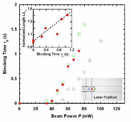
In the microchannel shown in Fig. 2, we measured the variation of the blocking time with respect to laser power and forcing position. We observe that increases approximately linearly with the power, above an initial threshold, showing a weak position-dependence of the laser spot. Furthermore, the inset of Fig. 2 shows that the droplet length varies linearly with , as expected from mass conservation at constant water flowrate , being the droplet length without laser and m2 the channel cross section. The best linear fit to the data gives an effective water flowrate L/min, close to the nominal value L/min, showing that the water flowrate remains controlled even in presence of the laser forcing. Thus, the optical forcing provides a tunable valve which provides control over droplet timing and size. Similar blocking is observed in a T geometry or if the flows are driven at constant pressure. However, the blocking is only obtained when the light is absorbed, here by using a dye.
We visualize the convection rolls produced by the heating by placing tracer particles in both fluids, as shown in Fig. 3(a) for a drop that is blocked in a straight channel. For pure liquids, the direction of Marangoni flow along the interface is directed from the hot (low surface tension) to the cold (high surface tension) regions. However, the flows in our experiments point towards the laser along the interface, indicating an increase of surface tension with temperature. This is consistent with previous studies that have shown a linear increase of surface tension with temperature in the presence of surfactants Berge et al. (1994); Sloutskin et al. (2005); sur .
One important constraint for practical applications is the amplitude of the temperature rise. Since the materials used in this study have similar thermal properties (thermal diffusivity m2s-1, thermal conductivity Wm-1K-1), we estimate the maximum temperature in the flow by modeling the heating produced by a laser absorbed in a single fluid phase Gordon et al. (1965), assuming thermal diffusion as the only energy transport mechanism. Considering the measured optical absorption of our water/dye solution m-1, and assuming that the temperature m away is fixed by the flowing oil at room temperature, we find K for the temperature rise at the laser focus for a beam power P = 100 mW. The temperature gradient is steep near the focus, with the temperature dropping to 5 K at m from the beam spot. However, note that given the typical flow velocity ( mm/s) and the characteristic length scale over which thermal diffusion occurs (m), the thermal Peclet number is comparable to unity. Thus, our calculation overestimates the actual overheating.
The force generated by the convective flow on a droplet is investigated through the depth-averaged Stokes equations, since our channels have a large width/height aspect ratio Boos and Thess (1997). The detailed modeling will be discussed in a subsequent publication; here we limit ourselves to the main features: a circular drop of radius is considered in an infinite domain and the flow due to the Marangoni stresses is evaluated. Assuming a parabolic profile in the small dimension () and introducing a streamfunction for the mean velocities in the plane of the channel, the depth averaged equations, valid in each fluid, are
| (1) |
where the depth-averaged velocities may be retrieved from and . The kinematic boundary conditions at the drop interface () are zero normal velocity and the continuity of the tangential velocity. The normal dynamic boundary condition is not imposed since the drop is assumed to remain circular, which is consistent with our experimental observations, Fig. 3a. Finally, the tangential dynamic boundary condition, which accounts for the optically-induced Marangoni stress, is
| (2) |
where are the dynamic viscosities and are the velocities in the drop and the carrier fluid, respectively. is the surface tension to temperature gradient, which is positive in our case.
For simplicity, we approximate the steady state temperature distribution using a Gaussian form , where is the maximum temperature difference between the hot spot and the far field and corresponds to the size of the diffused hot spot, which is significantly larger than Gordon et al. (1965). The equations are nondimensionalized using as temperature scale, as length scale, as force scale and as time scale, the remaining nondimensional groups being the aspect ratio , the nondimensional hot spot size and the viscosity ratio .

A typical predicted flow field solving the above numerical formulation is shown in Fig. 3(b), in which the four recirculation regions are clearly visible. The velocity gradients display a separation of scales in the normal and tangential directions, as observed from the distance between the streamlines in the two directions. Indeed, it may be verified that the velocities vary over a typical length scale in the normal direction, while the tangential length scale is given by .
Along with this flow field, we compute the pressure field, as well as the normal () and tangential viscous shear stresses in the external flow. Their projections on the axis, shown in the inset of Fig. 3(c), are then summed and integrated along to yield the total dimensionless force () on the drop. Note that the global component of the force is negative and therefore opposes the transport of the drop by the external flow. The component vanishes by symmetry and the integral of the wall friction may be shown to be zero since the drop is stationary. Numerically computed values of are shown by the isolated points in Fig. 3(c) as a function of , for different values of the aspect ratio . The points all collapse on a single master curve, displaying a nondimensional scaling law , for small .
The dimensional form of the force can be obtained, for small and , by considering the three contributions separately and noting that the velocity scale in this problem is imposed by the Marangoni stress. Using the separation of scales along the azimuthal and radial directions, Eq. 2 becomes , where the ’’ is understood as an order-of-magnitude scaling. This yields the characteristic tangential velocity scale
| (3) |
The force due to the tangential viscous shear is then obtained by multiplying by and integrating on the portion of the interface,
| (4) |
The force due to the normal viscous shear can be shown to scale like and is therefore negligible. The pressure force, on the other hand, derives from a balance between the pressure gradient and the radial second derivative of velocity. In the present circular geometry, similar scaling arguments yield a law for the contribution of the pressure force , which follows the same scaling as , resulting in the same scaling law for the total force . A rigorous derivation (to be published elsewhere) yields the final form of the force including the prefactor:
| (5) |
This expression is represented (once non-dimensionalized) by the straight line on Fig. 3(c) and agrees very well with the numerically computed values.
The physical value of the force for a typical experiment is estimated by taking Nm-2s (water), (hexadecane), and extracting mNm-1K-1 from Ref. Sloutskin et al. (2005). This yields a force on the order of 0.1 N, which is of the same order as the drag force on a drop in a large aspect ratio channel Nadim et al. (1996), thus confirming that thermocapillary forcing can indeed account for the blocking. Note that the force we calculate is several orders of magnitude larger those generated from electric fields Ahn et al. (2006) or optical tweezers Grier (2003).
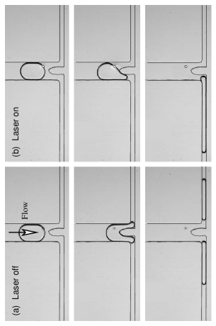
This blocking force may be applied at different locations in a microchannel by displacing the laser spot. In particular, we demonstrate the sorting of drops, a fundamental operation in the implementation of lab-on-a-chip devices. Drops are formed, as above, in a cross-junction and arrive at a symmetric bifurcation, carried by the continuous phase. In the absence of laser forcing, the drops arriving at the bifurcation divide into two equal parts Link et al. (2004), Fig. 4(a). When the laser is applied, the water-oil interface is asymmetrically blocked on the right hand side while the left hand side continues to flow, Fig. 4(b). Above a critical laser power (approximately 100 mW for the present configuration), the drop is blocked long enough that it is completely diverted through the left hand channel (see supporting video 2). Drops may therefore be sorted by accordingly selecting the laser position.
In summary, we have experimentally and theoretically demonstrated the efficiency of laser-driven blocking of water-in-oil drops. The theoretical treatment brings out two length scales, and . While and can be thought of as determining the typical scales for velocity variations in the radial and azimuthal directions, enters the force scaling as a local radius of curvature rather than the actual size of the drop. It is therefore not surprising that the blocking force should increase as decreases. On the other hand, the drag force due to the external flow scales as Nadim et al. (1996), implying that the laser power necessary to counterbalance the drag quickly decreases with the drop size. This, along with the rapidity of viscous and thermal diffusion while thermal inertia is reduced, all lead to laws favorable to miniaturization. The generality of the process provides a practical new way for acting on individual droplets, at any location, while working inside the robust environment of the microchannel.
We acknowledge help from Julien Buchoux, David Dulin and Emilie Verneuil. This work was partially funded by the CNRS PIR “Microfluidique et Microsystèmes Fluidiques”, the Conseil Régional d’Aquitaine, and the convention X-DGA.
References
- Miller et al. (2006) O. Miller, K. Bernath, J. Agresti, G. Amitai, B. Kelly, E. Mastrobattista, V. Taly, S. Magdassi, D. Tawfik, and A. Griffiths, Nature Methods 3, 561 (2006).
- Thorsen et al. (2001) T. Thorsen, R. Roberts, F. Arnold, and S. Quake, Phys. Rev. Lett. 86, 4163 (2001).
- Song et al. (2003) H. Song, J. Tice, and R. Ismagilov, Angew. Chem., Int. Ed. 42, 768 (2003).
- Joanicot and Ajdari (2005) M. Joanicot and A. Ajdari, Science 309, 887 (2005).
- Link et al. (2004) D. Link, S. Anna, D. Weitz, and H. Stone, Phys. Rev. Lett. 92, 054503 (2004).
- Young et al. (1959) N. Young, J. Goldstein, and M. Block, J. Fluid Mech. 6, 350 (1959).
- Balasubramaniam and Subramanian (2000) R. Balasubramaniam and R. Subramanian, Phys. Fluids 12, 733 (2000).
- Sammarco and Burns (1999) T. Sammarco and M. Burns, AIChE J. 45, 350 (1999).
- Darhuber et al. (2003) A. Darhuber, J. Valentino, J. Davis, S. Troian, and S. Wagner, Appl. Phys. Letters 82, 657 (2003).
- Garnier et al. (2003) N. Garnier, R. Grigoriev, and M. Schatz, Phys. Rev. Lett. 91, 054501 (2003).
- Sur et al. (2004) J. Sur, T. Witelski, and R. Behringer, Phys. Rev. Lett. 93, 247803 (2004).
- Kotz et al. (2004) K. Kotz, K. Noble, and G. Faris, Appl. Phys. Lett. 85, 2658 (2004).
- Lajeunesse and Homsy (2003) E. Lajeunesse and G. Homsy, Phys. Fluids 15, 308 (2003).
- Duffy et al. (1998) D. Duffy, J. McDonald, O. Schueller, and G. Whitesides, Anal. Chem. 70, 4974 (1998).
- Berge et al. (1994) B. Berge, O. Konovalov, J. Lajzerowicz, A. Renault, J. Rieu, M. Vallade, J. Als-Nielsen, G. Grübel, and J. Legrand, Phys. Rev. Lett. 73, 1652 (1994).
- Sloutskin et al. (2005) E. Sloutskin, C. Bain, B. Ocko, and M. Deutsch, Faraday Discuss. 129, 1 (2005).
- (17) A reduction the surfactant concentration reduced the efficiency of the blocking; a detailed exploration of surfactant effects will be addressed in a future study.
- Gordon et al. (1965) J. Gordon, R. C. C. Leite, R. S. Moore, S. P. S. Porto, and J. R. Whinnery, J. Appl. Phys. 36, 3 (1965).
- Boos and Thess (1997) W. Boos and A. Thess, J. Fluid Mech. 352, 305 (1997).
- Nadim et al. (1996) A. Nadim, A. Borhan, and H. Haj-Hariri, J. Colloid and Interface Science 181, 159 (1996).
- Ahn et al. (2006) K. Ahn, C. Kerbage, T. Hynt, R. Westervelt, D. Link, and D. Weitz, Appl. Phys. Lett. 88, 024104 (2006).
- Grier (2003) D. Grier, Nature 424, 810 (2003).