Fragmentation studies of high energy ions using CR39 nuclear track detectors
V. Togoa,111Corresponding author, togo@bo.infn.it, S. Balestraa, S. Cecchinia,b, D. Di Ferdinandoa, M. Fruttia, G. Giacomellia, M. Giorginia,
A. Kumara,c, G. Mandrioli a, S. Manzoora,d, A. Margiottaa, E. Medinacelia, L. Patriziia, V. Popaa,e, and M. Spurioa
aPhys. Dept. of the University of Bologna and INFN, Sezione di
Bologna, Viale C. Berti Pichat 6/2, I-40127 Bologna, Italy
bINAF/IASF Sezione di Bologna, 40129, Bologna Italy
cDept. Of Physics, Sant Longowal Institute of Eng. and Tech., Longowal
148 106 India
dPRD, PINSTECH, P.O. Nilore, Islamabad, Pakistan
eInstitute of Space Sciences, Bucharest R-77125, Romania
Presented at the 10th Inter. Symp. Radiat. Phys., Coimbra, Portugal, 17-22 Sept. 2006.
Abstract
We report on the measurements of the total charge changing
fragmentation cross sections in high-energy nucleus-nucleus collisions using
Fe, Si and Pb incident ions. Several stacks of CR39 nuclear track detectors
with different target combinations were exposed at normal incidence to high
energy accelerator beams to integrated densities of about 2000 ions/cm2.
The
nuclear track detector foils were chemically etched, and ion tracks were
measured using an automatic image analyser system. The cross section
determination is based on the charge identification of beam ions and their
fragments and on the reconstruction of their path through the stacks.
Keywords: CR39; nuclear track detector; chemical etching; charge identification; total charge changing cross section
PACS: 29.40.Wk; 25.75.-q; 25.70.Mn; 21.10.Ft
1 Introduction
Fragmentation studies of high energy ions are relevant for nuclear physics, cosmic ray physics, astrophysics and applied physics [1]. High energy heavy ion fragmentation cross-sections are also useful to describe the effects of primary cosmic radiation hitting spacecraft walls. Important applications of the propagation of fast heavy ion beams through matter are given in space radiation protection and in the field of cancer therapy [2].
In this paper we present experimental results on the fragmentation of 158 A GeV lead ions, 1 A GeV and 0.41 A GeV iron ions and 1 A GeV silicon ions. These measurements are part of a series of exposures at CERN, Brookhaven National Laboratory and CHIBA aimed to study the response of the CR39 nuclear detector and to determine the fragmentation cross sections of Pb, Fe and Si ions projectiles. Targets of C, CR39, CH2, Al, Cu and Pb were used; they were chosen to be thin enough to minimise multiple interactions and thick enough to produce a sufficient number of fragments.
2 Experimental procedure
We exposed several stacks made of CR39 nuclear track detectors and different targets to different energy beams at: CERN-SPS, 158 A GeV Pb82+; BNL-NSRL, 1 A GeV Fe26+ and Si14+; CHIBA, 0.41 A GeV Fe26+. Each stack has CR39 sheets upstream and downstream of the target. The exposures were performed at normal incidence. The charged fragments produced by projectile interactions with target nuclei keep most of the projectile longitudinal velocity. They can be detected after the target in CR39 detectors. Our CR39 sheets were manufactured by the Intercast Europe Co. of Parma, Italy, using a specially designed line of production [3].
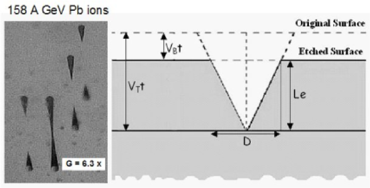
The detection principle of the CR39 [4] is based on the fact that a through-going heavily ionising particle produces a cylindrical radiation-damaged region along the ion trajectory creating a “latent track”. This damaged region is chemically reactive and can be etched by an appropriate chemical treatment. As a result, an etched cone is formed on both sides of each detector sheet, see Fig. 1. The cones are visible under a microscope. After exposure, the CR39 detectors were etched for 30 h in a 6N NaOH water solutions at a temperature of 70 .
An automatic image analyser system [5] was used to scan the detector surfaces and measure the etch-pit cone areas. For each etch-pit cone the base area, the eccentricity, the central brightness and the coordinates were measured.
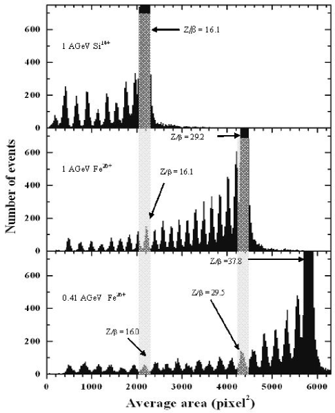
A tracking procedure was used to reconstruct the path of the beam and of the fragments. To better identify the projectile and fragment charges we performed an average of the measured etch-pit areas for each track in 3 or more sheets. Distributions of the etched cone base areas for CR39 detectors located after the fragmentation targets are shown in Fig. 2. Etched cone base areas are given for 1 A GeV Si14+, 1 A GeV Fe26+ and 0.41 A GeV Fe26+. Well separated peaks for the primary ions and for fragments are observed and a charge can be assigned to individual peaks; for a given z/ value, we have the same cone base area for different energies (Fig. 2).
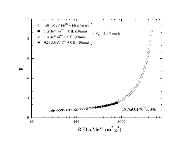
The reduced etch rate p=/, where and are the track and bulk etch velocities, respectively, was used to characterise the detector response [6,7]. It was determined on the basis of the surface area measurements of the etch-pits. The response of the detector is given by the relation p vs REL (Restricted Energy Loss); the REL was computed using the Bethe-Block formula (Particle Data Group). Fig. 3 shows the measured calibration curves (p vs REL) for relativistic Pb, Fe and Si ions.
3 Total charge-changing cross sections
For the determination of the total charge-changing cross sections, , the number of beam ions before the target (incident ions) and the number of beam ions after the targets were measured [8-11]. The target thicknesses were chosen to optimise the fragmentation process.
Our measured for the collisions of 158 A GeV Pb ions, 1 A GeV Fe26+ and Si14+ and 0.41 A GeV Fe26+ on different targets are given in the sixth column of Table 1. The fragmentation charge-changing cross section for beam ions was evaluated using the formula
| (1) |
where for each target; is the number of primary ions, the number of beam ions surviving after the target, the target density, the atomic mass of the target, the target thickness and is the Avogadro number. In this procedure, successive fragmentation processes are neglected. Hydrogen cross sections were obtained from the measured cross sections on carbon and on CH2 using the formula:
| (2) |
We compare our experimental cross-sections with the geometric collision cross section for a projectile of mass number on a target of mass number :
| (3) |
assuming = 1.35 fm and b = 0.83 [12]. These theoretical cross sections are given in the column of Table 1.
4 Conclusions
The total charge-changing cross sections in different targets were measured using beams of Pb nuclei of 158 A GeV, 1 A GeV Fe26+ and Si14+, 0.41 A GeV Fe26+ with CR39 nuclear track detectors placed before and after the targets, Table 1. Our results are in agreement with the theoretical values given by Eq. (3).
The calibration of the CR39 was determined by the relation p vs REL (Restricted Energy Loss) that shows that a unique curve gives the response of the detector at different energies.
We also exposed different stacks of CR39 to 3, 5 and 10 A GeV for both Fe and
Si ions at the BNL AGS. These studies are in progress and should become
available in the near future.
![[Uncaptioned image]](/html/physics/0611105/assets/x4.png)
Acknowledgements.We thank the staffs of CERN SPS, CHIBA and BNL AGS and NSRL for the beam exposures. We gratefully acknowledge the contributions of our technical staff, in particular E. Bottazzi, L. Degli Esposti, G. Grandi and C. Valieri. We thank INFN and ICTP for providing fellowships and grants to non-Italian citizens.
References
-
[1]
E.R. Benton et al., Nucl. Instr. Meth. B184 (2001) 255.
M. Ambrosio at al., Eur. Phys. J. C25 (2002) 511. - [2] U. Amaldi, Nucl. Phys. A 751 (2005) 409c.
- [3] L. Patrizii et al., Nucl. Tracks Radiat. Meas. 19 (1991) 641.
- [4] R. Fleischer, P.B. Price, R.M. Walker, Nuclear Tracks in Solids, Univ. of California Press, 1975.
- [5] A. Noll et al., Nucl. Tracks Radiat. Meas. 15 (1988) 265.
-
[6]
S. Cecchini et al., Nuovo Cimento A 109 (1996) 1119.
S. Balestra et al., accepted by Nucl. Instr. Meth. B, physics/0610227. - [7] S. Manzoor et al., Nucl. Instr. Meth. A 453 (2000) 525.
- [8] H. Dekhissi et al., Nucl. Phys. A 662 (2000) 207.
- [9] S. Cecchini et al., Nucl. Phys. A 707 (2002) 513.
- [10] I.E. Qureshi et al., Radiat. Meas. 40 (2005) 437.
- [11] Scampoli et al., Advances in Space Research 35 (2005) 230.
- [12] Y. He, P.B. Price, Z. Phys. A 348 (1994) 105.