On Impedance Bandwidth of Resonant Patch Antennas Implemented Using Structures with Engineered Dispersion
Abstract
We consider resonant patch antennas, implemented using loaded transmission-line networks and other exotic structures having engineered dispersion. An analytical expression is derived for the ratio of radiation quality factors of such antennas and conventional patch antennas loaded with (reference) dielectrics. In the ideal case this ratio depends only on the propagation constant and wave impedance of the structure under test, and it can be conveniently used to study what kind of dispersion leads to improved impedance bandwidth. We illustrate the effect of dispersion by implementing a resonant patch antenna using a periodic network of LC elements. The analytical results predicting enhanced impedance bandwidth compared to the reference results are validated using a commercial circuit simulator. Discussion is conducted on the practical limitations for the use of the proposed expression.
Index Terms:
Patch antenna, miniaturization, radiation quality factor, impedance bandwidth, loaded transmission lineI Introduction
Size reduction of patch antennas using different materials filling the volume under the antenna element is a classical miniaturization technique [1]. Typically, conventional dielectric substrates have been used to decrease the physical dimensions of the radiator, and it is known that the impedance bandwidth decreases roughly inversely with increasing the effective permittivity of the substrate (with a fixed substrate height) [2]. It has been observed, however, that increase of the effective substrate permeability has only a small effect on the bandwidth, if the permeability is assumed to be lossless and dispersion-free [2, 3]. This observation has lead to a flow of research concerning patch antenna miniaturization using magnetodielectric substrates, e.g. [4]–[6]. Recently, also several other exotic materials have been proposed for size reduction: For example, authors of [7] proposed to use a reactive impedance substrate, and authors of [8, 9] studied miniaturization using double-negative metamaterials.
From the commonly used transmission-line (TL) representation of a patch antenna [1] it is clear that the purpose of different loading materials is to optimize the input susceptance seen at the antenna terminal, while maintaining the radiation conductance at a reasonable level. If the antenna geometry leaves the radiation conductance intact, the dispersion characteristics of the loading material solely determine the impedance bandwidth performance of the antenna under test (AUT) compared to the performance of the same-size reference antenna, miniaturized using normal dielectrics. Authors of [5, 6] derived an analytical expression for the ratio of radiation quality factors () of the above referred antennas (resonant AUT and the reference antenna), and used this ratio as a figure of merit to test the suitability of different materials in efficient antenna miniaturization. derived in [5, 6] is solely a function of the effective AUT (substrate) material parameters, and it can be used when the material is homogeneous and it is meaningful to assign effective material parameters (for other criteria, please see [6]).
Recently, there have been suggestions to manipulate the dispersion characteristics of patch antennas by implementing the actual antennas as periodic networks of LC elements [10]–[12]. The aim has been to reduce the resonant length by synthesizing large propagation constants for the network. One interesting related idea would be to synthesize a network whose wave impedance and propagation constant resemble those of weakly dispersive high-permeability materials. If the implemented LC network comprising the antenna would still allow effective radiation (the radiation conductance would not deteriorate due to implementation details), one could possibly benefit from the advantages of magnetic loading [3] and weaken the strong “negative” effect of frequency dispersion [5]. This expectation follows from the important fact that the performance of the network is not based on resonant inclusions.
To be able to synthesize the desired dispersion characteristics for the network it would be convenient to have a figure of merit that would immediately tell if the proposed dispersion allows the realization of a wider impedance bandwidth than reference dielectrics. If the unit cell dimension is not very small, it might be more meaningful to characterize the network using its effective propagation constant and wave impedance, rather than the extracted material parameters [13]. Thus, proposed in [5, 6] might not be directly applicable. Here we derive a figure of merit, similar to that in [5, 6], but expressed as a function of the effective wave impedance and propagation constant of the structure/material under test. This figure of merit is used to design a patch antenna with enhanced impedance bandwidth compared to the reference antenna using a periodic network of LC elements.
II Formulation
Consider a rectangular patch antenna having width , height , and length . The volume under the patch element is loaded with a certain low-loss material. The TL-representation of the antenna is shown in Fig. 1. Using standard TL-equations we can write the input admittance of the antenna in the following form:
| (1) |
where is the characteristic admittance of the equivalent TL, is the radiation conductance, and is the equivalent propagation constant of the antenna segment. When the antenna operates close to its fundamental (parallel) resonance (), has a very small value. Thus, after applying Taylor expansion to the denominator of (1) we can write the input admittance in the following approximate form:
| (2) |
Typically the height of a resonant patch is a small fraction of the wavelength and noticeably smaller than the width of the antenna. By applying standard expressions, typically used to estimate the characteristic admittance and radiation conductance [1], we observe that , and the input admittance can further be simplified as
| (3) |

One of the definitions for the quality factor of a resonator operating close to its parallel resonance reads [14]
| (4) |
where is the input susceptance and is the operational angular frequency of the resonator. In our case eq. (4) is the radiation quality factor since only radiation losses are assumed. We get the following expression for the quality factor after differentiating the input susceptance:
| (5) |
Take a resonant patch antenna loaded with a dispersion-free dielectric material offering the same size reduction [] as a reference antenna. The ratio of the quality factors of the two antennas becomes
| (6) |
where we is the ratio of radiation conductances. In the quasi-static regime the propagation constant and characteristic impedance for the reference case read [14]
| (7) |
where are the free space wave number and wave impedance, respectively. From the requirement that both antennas should have the resonant length at the same frequency, we get a relation between and :
| (8) |
where is the phase velocity in the equivalent transmission-line of the AUT. Moreover, the relation between the effective wave impedance of the AUT and the characteristic impedance reads in our geometry [14]
| (9) |
After this the ratio of quality factors takes the form
| (10) |
II-1 Comparing the obtained expression with previously introduced expression
The ratio of (radiation) quality factors of ideally shaped resonant patch antennas (AUT and reference antenna) was derived in the following form in [5, 6]:
| (11) |
where are the AUT effective (substrate) material parameters (low losses are assumed). To derive eq. (11) authors of [5, 6] integrated the field energy density over the volume of the antenna, and further applied standard definitions to calculate the quality factors using stored electromagnetic energy and radiated power.
II-2 Comments related to the practical use of eq. (10)
When deriving eq. (11) authors of [5, 6] assumed that since the considered antennas had the same-size continuous metal plates acting as antenna elements, and the classical assumption according to which the width of the radiating edge predominantly determines the radiation conductance [1], was used. However, in the real antenna implementations based on LC element networks the actual (realizable) radiation properties might not be so easily predicted by standard TL-expressions: Authors of [10] observed that the power delivered to the furthermost radiating slot was 2 dB lower than the power delivered to the first slot. In addition to this, parasitic radiation from the inductors (affecting the fringing field) was reported. Later authors of [11] presented an empirical formula to estimate the radiation conductance of antennas based on LC-networks, and an expression to estimate the maximum achievable bandwidth. Authors of [12] reported rather low radiation efficiencies, and speculated that the low efficiencies were due to large currents concentrated near vias implemented as lossy conductors. In this case the standing wave pattern on the antenna element might not be anymore a pure -function as in a normal patch. This has a natural implication on the radiated power since most of the radiation should still happen due to fringing fields (represented as a conductance sitting at the patch edge where maximum of voltage should occur).
Due to the above uncertainties that depend highly on the particular implementation details, and the empirical expression for found in [11], we assume in the following generally that . With this assumption we are able to study the dispersion characteristics of the tested structures/materials separately from the radiation properties. If the proposed dispersion is desirable, one should still before the final implementation make sure that the antenna radiates properly.
III Example of application: Patch antenna implemented as an LC network
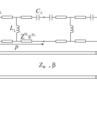
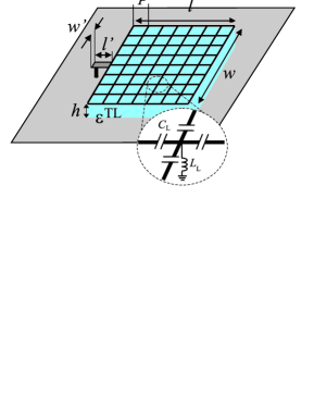
In this section we synthesize the performance of a compact patch antenna using a periodical arrangement of loaded transmission-lines, Fig. 2. We use eq. (10) to choose practically realizable network parameters so that goes below unity, i.e. the TL-antenna is more wideband than the same-size reference antenna. It is assumed that since we cannot at this stage readily predict the influence of the practical realization to the equivalent radiation conductance or voltage wave pattern.
The Bloch impedance and propagation constant in the one-dimensional (1D) line are calculated using the design equations available in [15]. Similarly as in [16] we relate the Bloch impedance to the effective wave impedance in the equivalent homogeneous line:
| (14) |
where is the unit cell period and is the height of the (network) substrate. With the help of eq. (10) we choose the following parameters (notations are clear from Fig. 2): mm, mm, , , pF, nH.
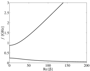
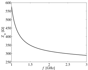
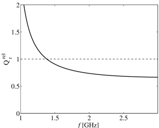
The equivalent propagation constant and wave impedance in the homogenized 1D line are shown in Figs. 3,4, respectively. The relative radiation quality factor [eq. (10)] is shown in Fig. 5. We can see that is below unity over a wide frequency band when the antenna operates in the right-hand branch (forward wave) of the dispersion curve. Initial simulations with different TL-structures111For which it is meaningful to assign effective material parameters due to very small period compared to the wavelength. have shown that the effective permeability is high and weakly dispersive only in the right-hand branch. This is reflected also in the result depicted in Fig. 5, which resembles the result obtained using weakly dispersive magnetic materials under the antenna element [5, 6].
The designed antenna has length mm and width mm (see the schematic illustration in Fig. 6) with the predicted resonant frequency around 2.5 GHz. The inductors and capacitors have been removed from the last periods near the radiating edges to minimize their effect on the fringing fields. We use data in Figs. 3, 4 to calculate the reflection coefficient for the TL-antenna using the TL-model introduced in [5, 6]. The calculation is repeated for a reference antenna loaded with dispersion-free dielectrics. In the TL-model, a short section of empty TL is left near the radiating edges to reflect the absence of bulk components (the same empty space is left in the reference calculation). In the calculations , and has been varied to tune the quality of matching to be the same with both antennas.
The results of calculations are depicted in Fig. 7. We have also implemented the TL-antenna in the Agilent ADS circuit simulator (no reference antenna simulations have been performed since the quantitative accuracy of the TL-model for this case has been demonstrated earlier [6]). Radiation has been modeled both in the TL-model and in ADS by an equivalent radiation conductance [1], see Fig. 1.
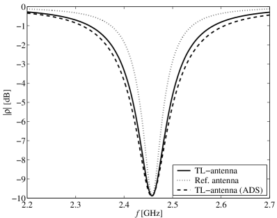
calculated from the reflection data is 0.66, whereas eq. (10) gives 0.69. The result predicted by ADS closely agrees with the TL-result (with a fixed ) and validates the feasibility of the proposed network (dispersion) in antenna miniaturization. We have to bear in mind, however, that in the practical LC network implementation the radiation might be weaker [10, 12] than predicted by the standard expressions for given in [1]. This effect is, however, highly dependent on the implementation details.
IV Conclusion
We have derived an explicit expression for the ratio of radiation quality factors of resonant patch antennas, 1) implemented using structures having engineered dispersion and 2) loaded with conventional dielectrics. This expression allows to study conveniently what kind of dispersion leads to efficient size reduction. As an example, a patch antenna with desirable dispersion characteristics has been implemented using a periodical network of LC elements.
Acknowledgement
The authors wish to thank Dr. S. Maslovski for useful related discussions conducted in the spring 2005. Mr. J. Holopainen, Mr. T. Kiuru, and Dr. V. Möttönen are acknowledged for additional simulations and help with the simulation software.
References
- [1] I. J. Bahl and P. Bhartia, Microstrip antennas, Massachusettes: Artech House, 1980.
- [2] D. R. Jackson and N. G. Alexopoulos, “Simple approximate formulas for input resistance, bandwidth, and efficiency of resonant rectangular patch,” IEEE Trans. Antennas Propag., vol. 39, no. 3, pp. 407–410, 1991.
- [3] R. C. Hansen and M. Burke, “Antennas with magneto-dielectrics,” Microw. Opt. Technol. Lett., vol. 26, no. 2., pp. 75–78, 2000.
- [4] H. Mossallaei and K. Sarabandi “Magneto-dielectrics in electromagnetics: Concept and applications,” IEEE Trans. Antennas Propagat., vol. 52, no. 6, pp. 1558–1567, 2004.
- [5] P. M. T. Ikonen, S. I. Maslovski, C. R. Simovski, S. A. Tretyakov, “On artificial magnetodielectric loading for improving the impedance bandwidth properties of microstrip antennas,” IEEE Trans. Antennas Propag., vol. 54, no. 6, pp. 1654–1662, 2006.
- [6] P. M. T. Ikonen, K. N. Rozanov, A. V. Osipov, P. Alitalo, S. A. Tretyakov, “Magnetodielectric substrates in antenna miniaturization: Potential and limitations,” IEEE Trans. Antennas Propag., in press (to appear Nov. 2006).
- [7] H. Mosallaei and K. Sarabandi, “Antenna miniaturization and bandwidth enhancement using a reactive impedance substrate,” IEEE Trans. Antennas Propagat., vol. 52, no. 9, pp. 2403–2414, 2004.
- [8] S. F. Mahmoud, “A new miniaturized annular ring patch resonator partially loaded by a metamaterial ring with negative permeability and permittivity,” IEEE Antennas Wireless Propagat. Lett., vol. 3, pp. 19–22, 2004.
- [9] S. Tretyakov and M. Ermutlu, “Modeling of patch antennas partially loaded with dispersive backward-wave materials,” IEEE Antennas Wireless Propagat. Lett., vol. 4, pp. 266–269, 2005.
- [10] M. Schussler, J. Freese, R. Jakoby, “Design of compact planar antennas using LH-transmission lines,” Proc. IEEE Microw. Theory. Techn. Int. Symp., Fort Worth, Texas, June 6–11, 2004, vol. 1, pp. 209–212.
- [11] M. Schussler, M. Damm, J. Freese, R. Jakoby, “Realization concepts for compact microstrip antennas with periodically loaded lines,” Proc. IEEE Microw. Theory. Techn. Int. Symp., Long Beach, California, June 12–17, 2005, vol. 1, pp. 1063–1066.
- [12] C.-J. Lee, K. M . K. H. Leong, T. Itoh, “Composite right/left-handed transmission line based compact resonant antennas for RF module integration,” IEEE Trans. Antennas Propag., vol. 54, no. 8, pp. 2283–2291, 2006.
- [13] C. Caloz and T. Itoh, Electromagnetic metamaterials: Transmission line theory and microwave applications, Hoboken, NJ: John Wiley Sons, 2004.
- [14] R. E. Collin, Foundations for microwave engineering, 2nd ed., New York: McGraw-Hill, Inc., 1992.
- [15] P. Alitalo, S. Maslovski, S. Tretyakov, “Three-dimensional isotropic perfect lens based on LC-loaded transmission lines,” J. Applied Physics, vol. 99, p. 064912, 2006.
- [16] A. Grbic and G. Eleftheriades, “Practical limitations of subwavelength resolution using negative-refractive-index transmission-line lenses,” IEEE Trans. Antennas Propag., vol. 53, no. 10, pp. 3201–3209, 2005.