Muon Cooling and Future Muon Facilities111* To appear in Proceedings of the XXXIII International Conference on High Energy Physics, Moscow, Russia, July 26 – August 2, 2006.
Abstract
Muon colliders and neutrino factories are attractive options for achieving the highest lepton-antilepton collision energies and the most precise measurements of the parameters of the neutrino mixing matrix. The performance and cost of these future facilities depends sensitively on how well a beam of muons can be cooled. The recent progress of muon-cooling prototype tests and design studies nourishes the hope that such facilities can be built during the next decade.
keywords:
collider; cooling; muon; neutrino; factory.1 Introduction
The muon offers important advantages over the electron for use in a high-energy collider:
-
1.
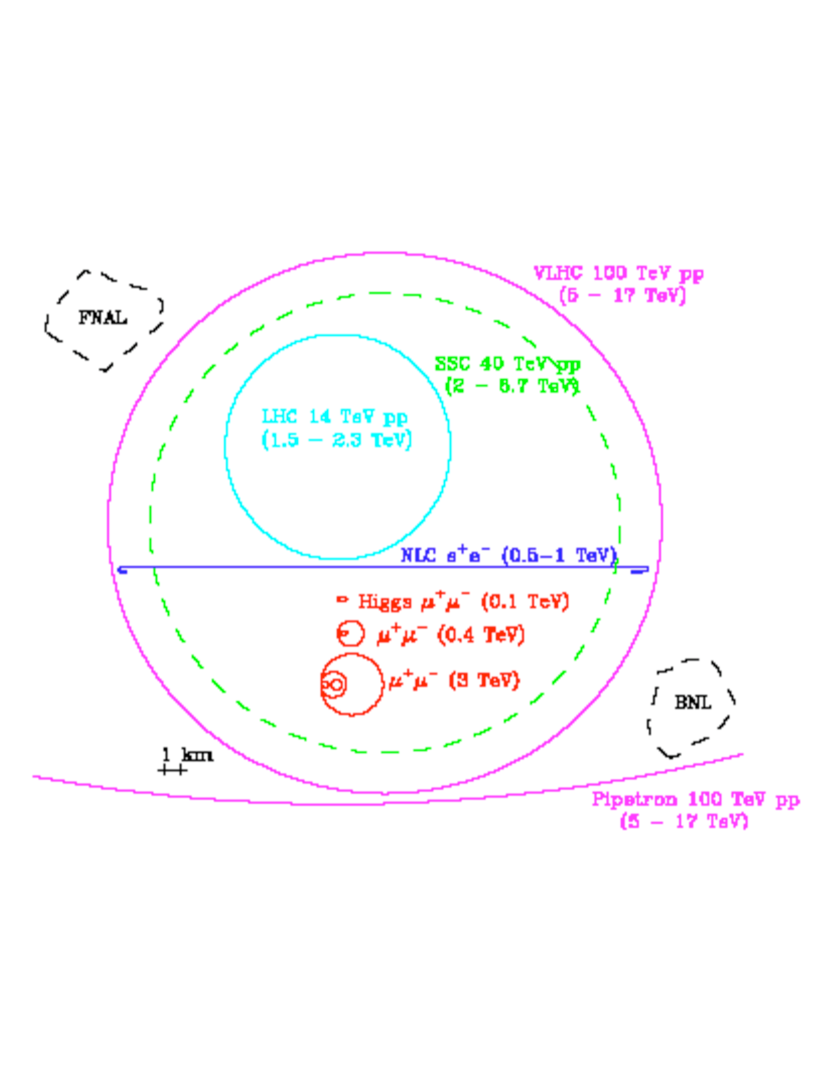
The suppression of radiative processes enables the use of storage rings and recirculating accelerators, reducing the size (Fig. 1) and cost of the complex.
- 2.
-
3.
“Beamstrahlung” interactions, which limit -collider luminosity as energy increases,[3] are negligible for muons.
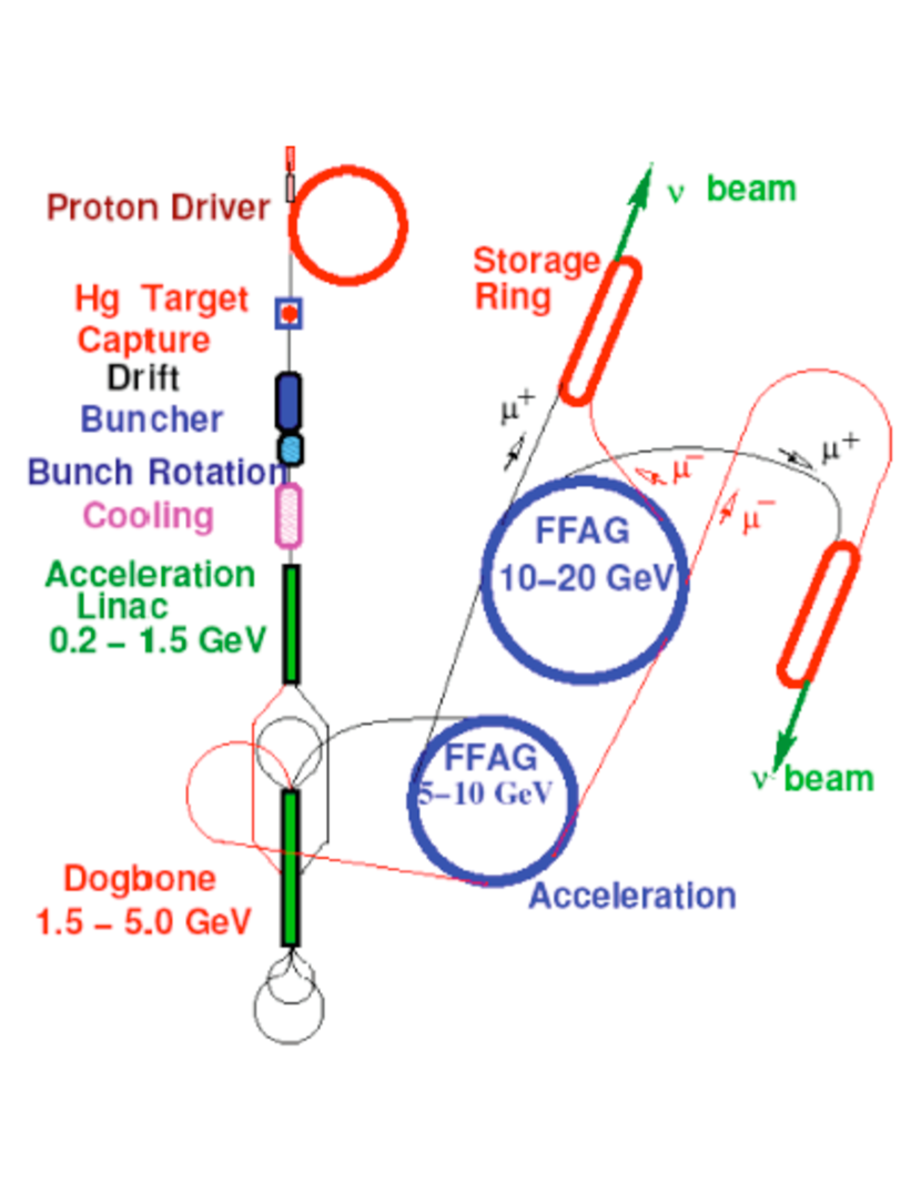
Moreover, a muon storage ring is an ideal source for long-baseline neutrino-oscillation experiments: via and , it can provide collimated, high-energy neutrino beams with well-understood composition and properties.[4] The very clean identification of final-state muons in far detectors enables low-background appearance measurements using and beams. The separation of oscillated from non-oscillated events requires only that the detector be magnetized so as to distinguish (the oscillated events if are stored in the ring) from (the oscillated events if are stored).
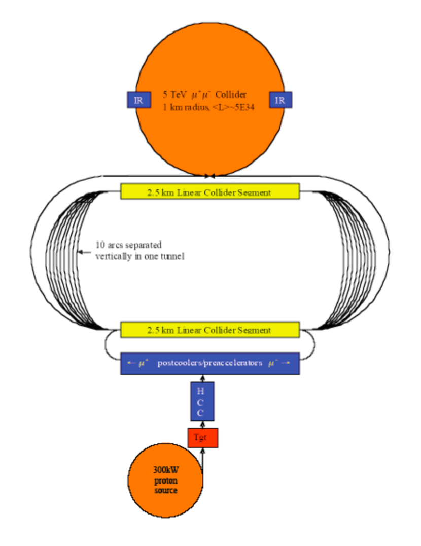
These advantages come with clear disadvantages: the short muon lifetime and large beam size require development of new, rapid beam manipulation and acceleration techniques if intense muon beams are to be accelerated, stored, or collided. Stored-muon “neutrino factories” (Fig. 2) and colliders (Fig. 3) benefit from muon-beam cooling,[5] which allows smaller-aperture (hence less costly) accelerators and higher luminosity.
2 Muon Cooling
Standard (electron, stochastic, and laser) beam-cooling methods are far too slow to be effective within the 2.2 s muon lifetime. However, the muon’s penetrating character enables rapid muon cooling via ionization.[7, 8] An ionization-cooling channel comprises energy absorbers and radio-frequency (rf) accelerating cavities placed within a focusing magnetic lattice. In the absorbers the muons lose energy by ionization; the rf cavities restore energy only along the beam axis. In this way, the (initially highly divergent) muon beam can be made more parallel.
Cooling is best understood in terms of normalized beam emittance , the volume of a beam in phase space, which is a constant of the motion both in linear beam transport and during acceleration. Cooling is the process of reducing a beam’s normalized emittance. In a medium, normalized transverse emittance depends on path length as[9, 10]
where is the muon velocity in units of , the muon energy in GeV, its mass in GeV/, the lattice betatron function, and the radiation length of the medium. A portion of this cooling effect can be transferred to the longitudinal phase plane by placing suitably shaped absorbers in dispersive regions of the lattice (“emittance exchange”)[8, 9, 10] or using path-length-dependent energy loss within a homogeneous absorber.[11] (Longitudinal ionization cooling per se is impractical due to energy-loss straggling.[10])
The terms of Eq. 2 represent muon cooling by energy loss and heating by multiple Coulomb scattering. Setting the two terms equal gives the equilibrium emittance , at which the cooling rate is zero and beyond which a given lattice cannot cool. Since the heating term scales with , a low requires low (i.e., high focusing strength) at the absorbers. Most design studies have used superconducting solenoids, which can give cm, as the focusing element of choice. Concerning , low- absorber media are favored, the best being hydrogen (approximately twice as effective for cooling as helium, the next best material[12]).
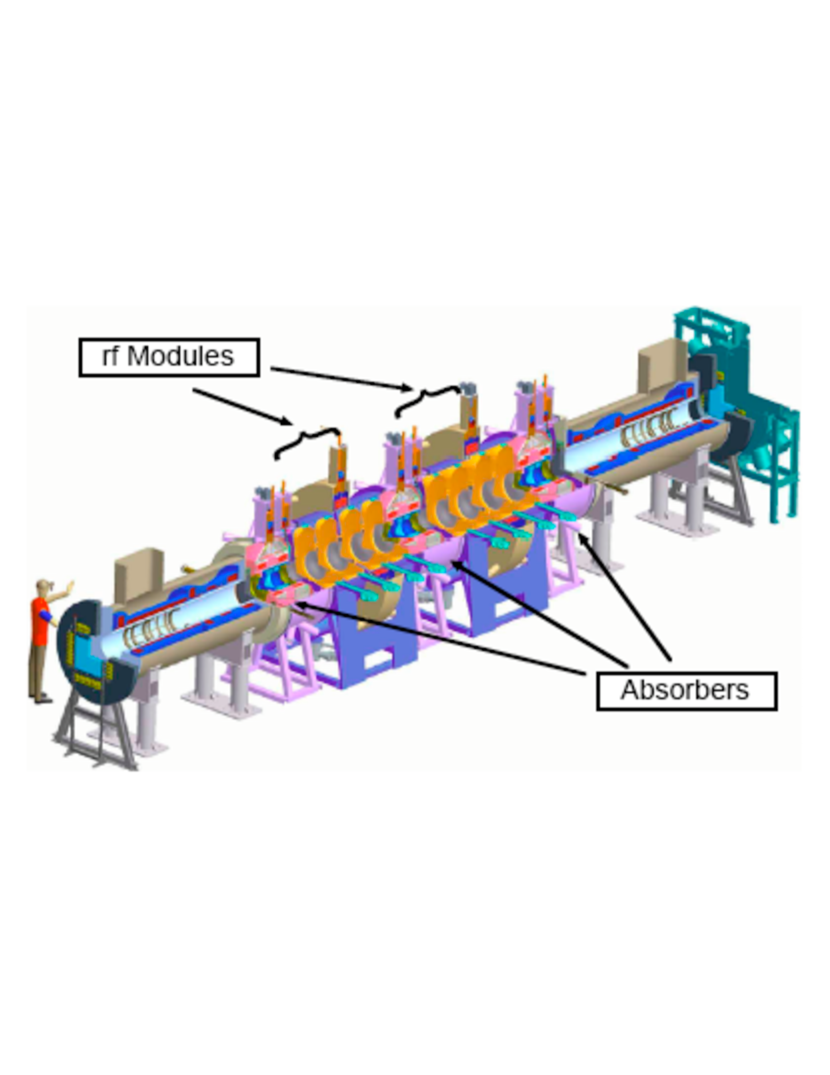
It is the absorbers that cool the beam, but for typical “real-estate” accelerating gradients ( 10 MeV/m, to be compared with MeV/m for liquid hydrogen[13]), the rf cavities dominate the length of the cooling channel (see e.g. Fig. 4). Ideally, the acceleration should exceed the minimum required for energy replacement, allowing “off-crest” operation. This gives continual rebunching, so that a beam with large momentum spread remains captured in the rf bucket. The achievable rf gradient thus determines how much cooling is practical before an appreciable fraction of the muons have decayed or drifted out of the bucket. High-gradient rf cavities (normal-conducting due to the magnetic field in which they must operate) for muon cooling are under development,[14] as is an alternative cooling approach: cavities pressurized with hydrogen gas, thus combining energy absorption and reacceleration.[15] In the first cooling stages the large size of the uncooled beam requires relatively low rf frequency. Goals are 15 MeV/m at 201 MHz in 2 T fields.
In the cooling term of Eq. 2, the percentage decrease in normalized emittance is proportional to the percentage energy loss, thus (approximating ) cooling in one transverse dimension by a factor 1/ requires 100% energy loss and replacement. Despite the relativistic increase of muon lifetime with energy, ionization cooling favors low beam momentum because of the increase of for momenta below the ionization minimum,[13] the greater ease of beam focusing, and the lower accelerating voltage required. Most muon-cooling designs have used momenta in the range 150400 MeV/. This is also the momentum range in which the pion-production cross section from thick targets tends to peak and is thus optimal for muon production as well as cooling. The cooling channel of Fig. 4 is optimized for a mean muon momentum of 200 MeV.
3 Towards a Muon Collider
Cooling lattices using longitudinal–transverse emittance exchange to cool simultaneously in all six dimensions are receiving increasing attention,[16, 17] from both the Neutrino Factory and Muon Collider Collaboration[18] and Muons, Inc.[19] These are essential to a high-luminosity muon collider and may enable higher-performance or lower-cost neutrino factories. As Fig. 3 suggests, muon colliders offer the prospect of much higher collision energies than are feasible with electrons; they thus provide a potential next step beyond the ILC.
4 Technology Demonstrations
The R&D on muon cooling[20] has identified a number of technologies crucial to future muon facilities, each of which has a demonstration experiment proposed or in progress:
-
1.
The MERIT (Mercury Intense Target) experiment, approved at CERN and under construction for operation in 2007; the goal is to show feasibility of a mercury-jet target for a 4 MW proton beam with solenoidal pion capture.[21]
- 2.
-
3.
EMMA (Electron Model of Muon Accelerator), proposal to build and operate at Daresbury Laboratory a model “non-scaling” FFAG accelerator.[23]
-
4.
MANX (Muon collider And Neutrino factory eXperiment), LoI to build and test a helical cooling channel segment.[19]
Experimental results may soon strengthen the physics case for a muon facility. With the key techniques established by 2010, a facility could then be built in the ensuing decade.
5 Acknowledgments
This work was supported by the US Dept. of Energy and the National Science Foundation.
References
- [1] V. Barger et al., Phys. Rept. 286, 1 (1997).
- [2] See e.g. E. Eichten, K. D. Lane, J. Womersley, Phys. Rev. Lett. 80, 5489 (1998) and references therein.
- [3] R. B. Palmer, J. C. Gallardo, in Proc. XXVIII Int. Conf. on High Energy Physics, ed. Z. Ajduk, A. K. Wroblewski (World Scientific, Singapore, 1997), p. 435.
- [4] S. Geer, Phys. Rev. D57, 6989 (1998); ibid. 59, 039903E (1999); C. Albright et al., Fermilab-FN-692 (May 2000); M. Apollonio et al., CERN-TH-2002-208 (Oct. 2002); M. Lindner, in Neutrino Mass, ed. G. Altarelli, K. Winter, Springer Tracts in Modern Physics 190, 209 (2003).
- [5] E.g., cooling is cost-effective and worth a factor 1.7 in intensity in the ISS design.[6]
- [6] M. S. Zisman, “ISS Accelerator Working Group Report,” NuFact 06 Workshop; available from http://nufact06.physics.uci.edu/Workshop/Program/Plenary.aspx; see also ISS web page http://www.hep.ph.ic.ac.uk/iss/.
- [7] Y. M. Ado, V. I. Balbekov, At. Energ. 31, (1) 40 (1971), English translation in Atomic Energy (Springer) 31(1) 731; A. N. Skrinsky, V. V. Parkhomchuk, Sov. J. Part. Nucl. 12, 223 (1981); D. Neuffer, Part. Acc. 14, 75 (1983); E. A. Perevedentsev, A. N. Skrinsky, in Proc. 12th Int. Conf. on High Energy Accelerators, ed. F. T. Cole, R. Donaldson (Fermilab, 1984), p. 485; R. Palmer et al., Nucl. Phys. Proc. Suppl. 51B, (1), 61 (1996).
- [8] For introductory discussions see D. Neuffer, Nucl. Instrum. Meth. A532, 26 (2004); D. M. Kaplan, SNOWMASS-2001-M102; more detailed treatments are in Ref. [10]; K. J. Kim, C. X. Wang, Phys. Rev. Lett. 85, 760 (2000); C. X. Wang, K. J. Kim, SNOWMASS-2001-T502; J. S. Berg, BNL-76794-2006-JA (Nucl. Instrum. Meth., in press).
- [9] C. M. Ankenbrandt et al., Phys. Rev. ST Accel. Beams 2, 081001 (1999).
- [10] D. Neuffer, CERN-99-12 (1999).
- [11] Y. Derbenev, R. P. Johnson, Phys. Rev. ST Accel. Beams 8, 041002 (2005).
- [12] D. M. Kaplan, in Proc. COOL’03 Workshop, ed. T. Katayama, T. Koseki, Nucl. Instrum. Meth. A532, 241 (2004).
- [13] W.-M. Yao et al. (Particle Data Group), J. Phys. G33, 1 (2006).
- [14] Y. Torun et al., in Proc. COOL05 Workshop, ed. S. Nagaitsev, R. Pasquinelli, AIP Conf. Proc. 821, 437 (2006).
- [15] P. Hanlet et al., Proc. EPAC 2006, p. 1364.
- [16] R. Palmer et al., Phys. Rev. ST Accel. Beams 8, 061003 (2005).
- [17] R. P. Johnson et al., in Proc. COOL05, op. cit., p. 405.
- [18] See http://www.cap.bnl.gov/mumu/.
- [19] See http://www.muonsinc.com/.
- [20] M. M. Alsharo’a et al., Phys. Rev. ST Accel. Beams 6, 081001 (2003).
- [21] See http://proj-hiptarget.web.cern.ch/proj-hiptarget/.
- [22] See http://www.mice.iit.edu/; K. Long, D. M. Kaplan, these Proceedings.
- [23] See http://hepunx.rl.ac.uk/uknf/wp1/ emodel/.