Channel plasmon-polaritons: modal shape, dispersion, and losses
Esteban Moreno and F. J. Garcia-Vidal
Departamento de Física Teórica de la Materia Condensada, Universidad Autónoma de Madrid, E-28049 Madrid, Spain
Sergio G. Rodrigo and L. Martin-Moreno
Departamento de Física de la Materia Condensada, Universidad de Zaragoza-CSIC, E-50009 Zaragoza, Spain
Sergey I. Bozhevolnyi
Department of Physics and Nanotechnology, Aalborg University, DK-9220 Aalborg Ost, Denmark
Abstract
We theoretically study channel plasmon-polaritons (CPPs) with a geometry similar to that in recent experiments at telecom wavelengths (Bozhevolnyi et al., Nature 440, 508 (2006)). The CPP modal shape, dispersion relation, and losses are simulated using the multiple multipole method and the finite difference time domain technique. It is shown that, with the increase of the wavelength, the fundamental CPP mode shifts progressively towards the groove opening, ceasing to be guided at the groove bottom and becoming hybridized with wedge plasmon-polaritons running along the groove edges.
OCIS codes: 240.6680, 130.2790, 260.3910.
The guiding of light within a subwavelength cross section has been recently attracting a great deal of attention due to ever increasing demands for miniaturization of photonic circuits. Light may be confined in the direction perpendicular to a flat metallic surface for energies below the metal plasma frequency. The mode guided along the metallic interface is known as surface plasmon-polariton (SPP). Various geometries have been proposed to achieve confinement of the plasmon-polariton in the plane transverse to the propagation direction[1, 2, 3, 4, 5]. Among these proposals, the plasmon-polariton guided by a V-shaped groove carved in a metal (channel plasmon-polariton, CPP) is particularly interesting. CPPs were theoretically suggested by Maradudin and coworkers[6] and subsequently studied in the visible regime[3, 7]. Recently, CPPs have been experimentally investigated at telecom wavelengths[8], displaying strong confinement, low damping, and robustness against channel bending. Thank to these properties, prototypes of basic devices could be demonstrated[9]. The mentioned devices have been developed with the help of the effective index approximation but, to our knowledge, no rigorous electrodynamic computation of CPPs at telecom wavelengths has been reported. The effective index approximation can deliver information about the dispersion relation, but it is expected to be inaccurate for frequencies close to the mode cutoff and is unable to determine modal shape and polarization. The functionality of many devices relies on the overlapping of electromagnetic fields at various sites inside the device. For this reason the knowledge of the modal shape is essential to provide a solid foundation for the design of CPP-based devices. Here we present rigorous simulations of guided CPPs aimed to elucidate their characteristics at telecom wavelengths, including full vectorial modes, dispersion, and losses. We show that, contrary to what is commonly believed, CPPs at telecom wavelengths are not guided at the groove bottom, at least for the groove parameters used in the experiments[8, 9]. Instead, the CPP field at the groove entrance hybridizes with wedge plasmon-polaritons (WPPs) running along the edges of the groove.
Our goal is to understand the fundamental CPP mode guided by realistic grooves at telecom wavelengths[8]. Nevertheless, in order to comprehend the behavior in this regime, which is close to cutoff, we will consider a broader spectrum, higher order modes, and a number of different geometries. The simulations have been performed with two rigorous electrodynamic techniques: the multiple multipole method (MMP)[10] and, where mentioned, the finite difference time domain (FDTD) method[11]. Within the MMP method the corners are rounded ( radius of curvature). FDTD results were converged for a mesh of about . Such fine meshes are essential, the more so for wavelengths shorter than . The grooves are carved in gold and we employ experimentally measured values of the dielectric permittivity .
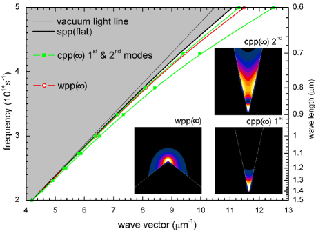
Figure 1 shows the dispersion relation for a non-truncated groove with a semiangle of and infinitely long sides. This structure sustains two modes, being termed CPP() (see right insets), which are outside the dispersion line of the SPP at a flat surface. The modal shape (time averaged electric field) is shown in the right insets for a wavelength of . In the figure it is also plotted the dispersion relation for a non-truncated metallic wedge of semiangle and infinitely long sides. The corresponding wedge mode running along the edge is termed WPP() (see left inset). WPP() for this will be relevant when we later truncate the above groove at a finite height: it corresponds to the edges at both sides of the finite-height groove. The WPP() modal field at is shown in the left inset. For increasing wavelength all three modes approach the SPP line (none of them has a cutoff). In this process the modal shapes remain qualitatively the same, the only difference being that the fields are expelled away from the groove or wedge corners.
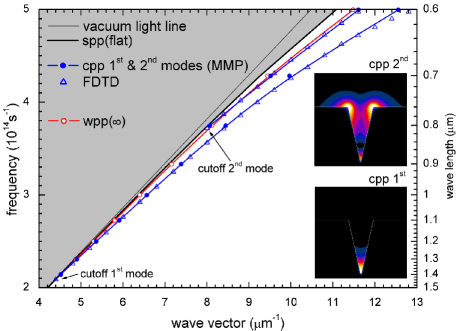
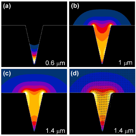
Figure 2 represents a similar plot but now a groove of finite height is considered, the height being . The CPP modes exhibit now cutoff at different wavelengths ( for the first mode and for the second one). This was advanced in Ref. 12, and it is a consequence of the above mentioned behavior of the fields for increasing wavelength. As the wavelength grows, the field is pushed out of the groove and, after a certain threshold, it can no longer be confined by the groove sides and is radiated in the form of SPPs along the contiguous horizontal metal surfaces. It is important to realize that, before reaching the SPP dispersion line, both modes approach and cross the WPP() line. This means that close to cutoff the CPP modes must be hybridized with the modes running on the edges at both sides of the groove. This idea is visualized in the insets, that render the modal shapes (time averaged electric field) at . At this wavelength the first mode is not close to WPP() and the hybridization does not take place, but it is already happening for the second mode. The described phenomenon is even more distinct in Fig. 3 displaying the fundamental mode for increasing wavelengths. It is observed that the CPP mode becomes more and more mixed with the WPP(). Close to cutoff (at about ) the mode is not guided at the groove bottom anymore but rather at the groove edges. A hint of this possibility was mentioned in Ref. 13. In the experiments, the edges at both sides of the groove have larger radius of curvature than in the previously presented simulations. We have verified that this does not alter our conclusion by repeating the same computation with a radius of curvature of at the groove edges (and keeping at the bottom). Figure 3(d) shows the instantaneous transverse electric field for this case and it is clear that hybridization with edge modes still occurs. The transverse electric field is approximately horizontal inside the channel (an assumption used by the effective index approximation), but it is not horizontal near the edges where the field is maximum. Let us note in passing the excellent agreement of the two techniques employed here (the residual discrepancy in Fig. 2 for the fundamental mode at is due to different rounding schemes of the groove bottom in the two methods). From the point of view of fabrication it is useful to mention that, for , the dispersion relation is extremely sensitive to the fine details of the groove bottom (e.g., rounding), as concluded after a large number of simulations where the details of the bottom were subjected to small perturbations. On the other hand, this does not happen for telecom wavelengths (as expected from the modal shape), a circumstance that has also been observed experimentally[9]. Note that the calculated cutoff wavelength of the fundamental mode is somewhat lower than the wavelengths used in the experiments. This discrepancy can be ascribed to (small) differences in the groove geometry, both in the groove shape (angle, side flatness) and in the groove depth, and/or different dielectric permittivity of gold. We have verified (not shown here for brevity) that slightly less negative or/and smaller groove semiangle leads to a higher cutoff wavelength. Finally, the experiments were conducted at ambient conditions so that water condensation could not be excluded (a very thin water layer can significantly increase the cutoff wavelength).
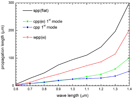
The effect of absorption is summarized in Fig. 4 that renders the propagation length , versus wavelength for the various considered structures ( is the modal wave vector). The propagation lengths are in all cases smaller than that of SPPs at a flat surface. This is a consequence of the field enhancement at the corners and the field confinement that decreases the portion of field propagating in air. When comparing the CPP modes it is observed that the effect of truncation at a finite height is only important for wavelengths larger than , which is reasonable because the field is very much confined at the groove bottom for smaller . For longer wavelengths the CPP propagation length is decreased as compared to that of CPP(). At we find that . The values reported in Ref. 8 at are twice as large. The discrepancy can be again ascribed to slight differences in geometry and/or dielectric permittivity that rise the cutoff wavelength. If the trend of the line corresponding to the CPP is extrapolated, we find good agreement with the reported data. It is to be observed that the propagation length of WPP() is significantly higher, a fact that could find obvious applications.
In conclusion, we have presented rigorous computer simulations of CPPs at telecom wavelength. CPPs have been fully characterized in terms of modal shape, dispersion, and losses. We have shown that, for relatively shallow grooves, the field is guided at the groove opening and is hybridized with modes running along the groove edges (WPPs). We expect that our findings will be of help for the design of improved CPP devices.
References
- [1] J. Takahara, S. Yamagishi, H. Taki, A. Morimoto, and T. Kobayashi, Opt. Lett. 22, 475 (1997).
- [2] P. Berini, Opt. Lett 24, 1011 (1999).
- [3] D. F. P. Pile and D. K. Gramotnev, Opt. Lett. 29, 1069 (2004).
- [4] D. F. P. Pile, T. Ogawa, D. K. Gramotnev, T. Okamoto, M. Haraguchi, M. Fukui, and S. Matsuo, Appl. Phys. Lett. 87, 061106 (2005).
- [5] D. F. P. Pile, T. Ogawa, D. K. Gramotnev, Y. Matsuzaki, K. C. Vernon, K. Yamaguchi, T. Okamoto, M. Haraguchi, and M. Fukui, Appl. Phys. Lett. 87, 261114 (2005).
- [6] I. V. Novikov and A. A. Maradudin, Phys. Rev. B 66, 035403 (2002).
- [7] D. F. P. Pile and D. K. Gramotnev, Opt. Lett. 30, 1186 (2005).
- [8] S. I. Bozhevolnyi, V. S. Volkov, E. Devaux, and T. W. Ebbesen, Phys. Rev. Lett 95, 046802 (2005).
- [9] S. I. Bozhevolnyi, V. S. Volkov, E. Devaux, J.-Y. Laluet, and T. W. Ebbesen, Nature 440, 508 (2006).
- [10] C. Hafner, Post-Modern Electromagnetics (Wiley, Chichester, 1999).
- [11] A. Taflove and S. Hagness, Computational Electrodynamics: The Finite-Difference Time-Domain Method (Artech House, Boston, 2000).
- [12] D. K. Gramotnev and D. F. P. Pile, Appl. Phys. Lett. 85, 266323 (2004).
- [13] V. S. Volkov, S. I. Bozhevolnyi, E. Devaux, and T. W. Ebbesen, Opt. Express 14, 4494 (2006).