LAL/RT 06-08
EUROTeV-Report-2006-067
CARE/ELAN 2006-007
June 2006
OPTIMIZATION OF THE OPTION FOR THE ILC††thanks: Work supported in part
by FP5 (PROBE FOR NEW PHYSICS) contract RTN2-2001-00450, FP6 (CARE) contract
RII3-CT-2003-506395 and (EUROTEV) contract RIDS-011899
Abstract
The running mode is one of the interesting physics options at the International Linear Collider (ILC). The luminosity for collisions is reduced by the beam-beam effects. The resulting beamstrahlung energy loss and beam-beam deflection angles as function of the vertical transverse offset are different compared to the collisions. In this paper, the dependence of these observables with the offset for different beam sizes has been analyzed to optimize performances for the mode, taking into account the requirements of the beam-beam deflection based intra-train feedback system. A first study of the implications for the final focus and extraction line optics is also presented for the cases of the 20 mrad and 2 mrad ILC base line crossing angle geometries.
1 BEAM-BEAM EFFECTS
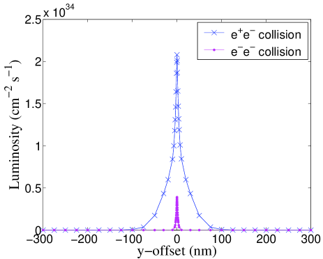
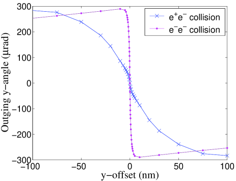
At the Interaction Point (IP) of the ILC, beam-beam effects due to the strong electromagnetic fields that the bunches experience during collisions cause a mutual focusing, called pinch effect, which enhances the luminosity in the case of collisions. The opposite is true for collisions. In this case the luminosity is reduced by mutual defocusing, or anti-pinching and is only about 20 of the one (see Fig. 1). Moreover this repulsion between the bunches causes the luminosity to drop with a vertical offset at the IP much more rapidly for the case than for . Another effect of this strong repulsive electromagnetic field is the much steeper beam-beam deflection curve (see Fig. 2). Since the fast intra-train feedback system used to maintain the beams in collision at the IP [1] exploits these deflections as its main signal and because of the higher sensitivity to the vertical offsets, it is important to compare average performances for and for a set of representative values of initial beam offsets and bunch-to- bunch jitter.
2 FEEDBACK SIMULATION
A simplified simulation of the feedback has been carried out using parametrized information from the last bunch crossing with a single proportional factor to relate the measured deflection angle of the outgoing beam to the correction of the offset at the IP [2]. At frequencies of a few Hz corresponding to the ILC train repetition rate, offsets of order of hundreds of nm are predicted (see e.g. [3]). In addition bunch-to-bunch jitter of a fraction of the beam size can be expected. The simulation has been done for different assumptions on the initial train offset and bunch-to-bunch jitter, and including a 10 error on the correction to represent the measured uncertainties. The factor relating the correction to the measured deflection angle was optimized, independently for and beam parameters, to maximize the speed of the correction without amplifying the bunch-to-bunch jitter by over-correcting. Nominal beam parameters [5] were used at 500 GeV. The average luminosity loss over a train was found to be almost independent of the offset at the beginning of the pulse for the range considered (up to 500 nm). The luminosity loss was however found to be a factor 2 greater compared to for the same assumption on the jitter.This is due to the greater sensitivity to the vertical offset. The ability to decrease this sensitivity with alternative beam parameters could be important if jitter conditions are worse than expected, e.g. during early ILC operation.
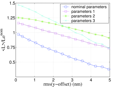
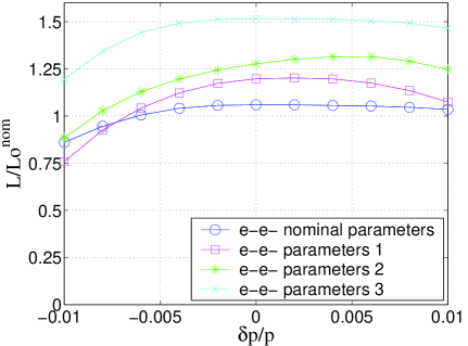
With this purpose, sets of alternative beam parameters with smaller disruption have been derived by decreasing the bunch length and varying the transverse beam sizes, in order to maximize the luminosity while limiting the beamstrahlung energy loss to 5 (see Table 1). These alternative parameters have increased luminosity, and some of them smaller sensitivity to the IP offset, compared to those obtained for the nominal case for . The average train luminosity for different amplitudes of the jitter applied to each beam, is also improved compared to the nominal parameters (see Fig.3).
| nom. | set 1 | set 2 | set 3 | low P | |
| 1 | 1 | 1 | 1 | 0.5 | |
| / | 1 | 0.7 | 0.5 | 0.5 | 0.5 |
| / | 1 | 0.7 | 0.8 | 0.9 | 0.7 |
| / | 1 | 1.5 | 1.5 | 1 | 0.6 |
| (m) | 10 | 10 | 10 | 10 | 9.6 |
| (m) | 0.04 | 0.04 | 0.04 | 0.04 | 0.03 |
| (mm) | 21.0 | 10.3 | 13.4 | 17.0 | 10.0 |
| (mm) | 0.4 | 0.9 | 0.9 | 0.4 | 0.2 |
| 3.9 | 4.6 | 4.9 | 5.8 | 3.0 | |
| () | |||||
| () | 2.24 | 4.9 | 5.0 | 4.3 | 2.2 |
An additional set of parameters is also being investigated with only half of the bunch charge, while keeping the same number of bunches per train. It has a smaller peak luminosity (see Table 1) and similar sensitivity to IP offsets as the nominal case. Such a parameter set could be important for early ILC operation and flexibility.
3 OPTICS STUDIES FOR THE CROSSING-ANGLE GEOMETRY
3.1 Final focus
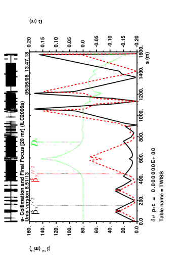
The optics of the Final Focus (FF) (corresponding to the 20 mrad crossing-angle geometry) has been refitted to obtain the new -functions at the IP for the alternative beam parameters in Table 1. Only the quadrupoles upstream of the chromatic correction section and the sextupoles were readjusted. This allows to maintain the geometry and overall optimization of high order effects. The -functions and the dispersion for the parameter set 2 in Table 1 are shown in Fig. 4.
The optical bandwidth for the different sets of parameters has been studied, considering beams with a uniform flat momentum distribution with an energy spread of 0.1. The distribution of particles at the entrance of the FF, was created with PLACET [6] for different average momentum offsets. The beam was then tracked through the FF with MAD8 [7] and used as input for GUINEA-PIG to compute the luminosity. The results (see Fig. 5) show similar off-momentum behavior for all parameter sets, with the alternative sets having better peak performance.
3.2 Extraction line
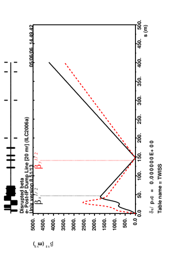
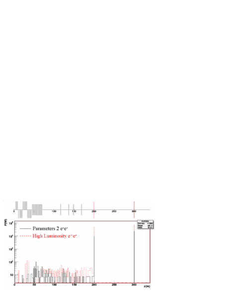
The effective parameters corresponding to the disrupted beam have been computed along the extraction line for the different beam parameter sets in Table 1 (see Fig. 6), and for the different parameters sets suggested for in [5]. The largest values found for the -functions in the and cases were comparable. The tracking of the disrupted beams has been simulated with BDSIM [8] and the power losses along the line have been computed. For the parameter set 2 the losses are smaller than for the high luminosity parameters for (see Fig. 7).
4 OPTICS STUDIES FOR THE CROSSING-ANGLE GEOMETRY
In the 2 mrad crossing-angle geometry the spent beam is transported off-axis through the last defocussing quadrupole of the final focus. The kick produced by this quadrupole is used to extract the spent beam. This scheme doesn’t work for the option unless one can reverse the signs of the focusing and defocusing final doublet quadrupoles (and sextupoles), while keeping at least the strength of the last quadrupole to maintain the kick needed for extraction. A first attempt in this direction [9] indicated that this was feasible, but large -value had to be used at the IP to limit the vertical beam size in the final doublet, which is important to keep reasonable collimation depth. This resulted however in about a factor 2 lower peak luminosity. Improvements with half the bunch length are also being investigated, with for example mm. In this case, more acceptable overall performance is expected.
5 CONCLUSIONS AND PROSPECTS
For the 20 mrad crossing-angle geometry, beam parameters can be obtained for the option by decreasing the bunch length, with improved peak luminosity, smaller sensitivity to IP offsets, and similar beam losses in the extraction line as those found for . For the 2 mrad crossing-angle, it is necessary to go to larger vertical beam sizes at the IP, which decreases the luminosity. With half of the bunch length and optimizing the transverse beam sizes taking into account collimation requirements, a first study indicates that some of this reduction can be recovered. In the near future, these problems will be studied to further characterize the option at the ILC.
References
- [1] G. White, N. Walker, D. Schulte, “An Example of Integrated Simulations- A LINAC to IP Simulation of the TDR TESLA Accelerator”, CARE/ELAN Document-2004-013.
- [2] I. Reyzl and S. Schreiber, International Journal of Modern Physics A Vol. 15 No. 15 (2000) 2495-2505.
- [3] A. Seryi, “Stability and Ground Motion Challenges in Linear Colliders”, ICFA Nanobeam 2002 Workshop.
- [4] D. Schulte, Ph.D. thesis, University of Hamburg 1996, TESLA-97-08.
- [5] D. Schulte, “Beam-Beam Simulations of the Proposed ILC Parameters”, EUROTeV- Memo-2005-004-1.
- [6] D. Schulte et al., The Tracking Code PLACET, http://dschulte.web.cern.ch/dschulte/placet.html.
- [7] The MAD program, http://hansg.web.cern.ch/hansg/mad/mad8.
- [8] G. Blair, BDSIM (Beam Delivery Simulation) code based on GEANT4.
- [9] A. Seryi, “Running 2mrad IR in the e-e- mode: BDS constraints”, presented at Snowmass, August 2005.