Surface Waves on a Semi-toroidal Water Ring
Abstract
We study the dynamics of surface waves on a semi-toroidal ring of water that is excited by vertical vibration. We create this specific fluid volume by patterning a glass plate with a hydrophobic coating, which confines the fluid to a precise geometric region. To excite the system, the supporting plate is vibrated up and down, thus accelerating and decelerating the fluid ring along its toroidal axis. When the driving acceleration is sufficiently high, the surface develops a standing wave, and at yet larger accelerations, a traveling wave emerges. We also explore frequency dependencies and other geometric shapes of confinement.
In 1831, Faraday first observed that surface waves on a vibrated fluid volume oscillate at half the driving frequency Faraday31 . These Faraday waves demonstrate the surface instability caused by strong oscillatory accelerations exerted on the fluid volume. Benjamin & Ursell showed that the amplitude of a surface eigenmode obeys the Mathieu equation Benjamin54 ; Miles90 . It follows that the superposition of multiples of harmonics and subharmonics are also solutions to the Mathieu equation. In the presence of finite viscosity, however, the subharmonic response is dominant Kumar96 ; Cerda98 ; Chen99 .
Previous experiments have revealed that patterns of various symmetries, such as striped Edwards93 ; Daudet95 , triangular Muller93 , square Lang62 ; Ciliberto91 ; Edwards94 , and hexagonal Kumar95 ; Kudrolli96 , can be excited on the free surface of a fluid layer. Quasi-one dimensional surface waves have also been studied in both narrow annular and channel geometries Keolian81 ; Douady90 ; Vega01 ; Mancebo02 . In these experiments, the standing waves often interact with the meniscus that forms at the bounding walls. The contact point and length-scale of this meniscus continually change as a result of the vertical oscillations. Consequently, the meniscus emits waves towards the bulk Douady90 . In other experiments, to remove this meniscus effect, the contact point is pinned on a sharp edge or brim Benjamin79 ; Martel98 ; Westra03 .
A curved fluid surface, such as on a hemi-spherical drop Lamb32 ; Bisch82 ; Wilkes97 ; Frohn00 ; Noblin04 , has been used to study surface waves in a confined geometry without bounding walls. Vibrating the drop causes waves to form on the curved surface, and for high external forcing, droplets are ejected. This process, termed atomization, provides one way to create a spray James03a ; James03b . The instability of the drop’s semi-spherical surface has been utilized for spray cooling, mixing, and humidification.
Faraday instability has been well studied both in flat fluid surfaces Edwards94 ; Daudet95 ; Kumar95 ; Kudrolli96 confined by the lateral boundaries and in sessile (pendant) drops Bisch82 ; Wilkes97 ; James03a ; Noblin04 . The differences between the two cases are their aspect ratios and boundary conditions (moving lateral contact lines or the capillary pinning). The geometry of our interest lies between the two cases: the semi-toroidal geometry is spatially extended with high aspect ratios (system size/capillary length) and pinning boundary conditions apply. It is however much less studied compared to the above two settings. Here, we employ a hydrophobic/hydrophilic patterning of a surface to confine a water volume to a specific region. In particular, if part of a hydrophilic substrate (low surface energy) is covered by a hydrophobic coating (high surface energy; we use Fluorothane ME; Cytonix Corp.), water is prevented from spreading beyond the hydrophilic region. The boundary between the two regions acts as an edge upon which the fluid contact point is pinned.
In the experiment we report here, the hydrophilic region is a thin annulus, and water placed there forms into a semi-toroidal volume with two pinned contact lines. We find that surface waves first develop along the centerline of the torus, which allows us to study quasi-one dimensional waves on a curved surface.
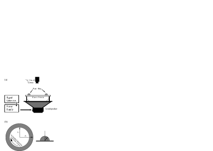
The schematic of our experimental setup is shown in Fig. 1. The annular hydrophilic region has inner radius cm and outer radius cm. The patterned glass plate is rigidly connected to a speaker, which oscillates the plate vertically at a controlled driving frequency and amplitude. A high-speed video camera is centered above the plate along the axis of the annulus. Since the semi-torus of water has a cross-sectional radius ( cm) that is relatively small in comparison to the distance between the plate and the camera, bright regions of the water ring seen in top-viewed video frames correspond to local extrema of the fluid surface height.
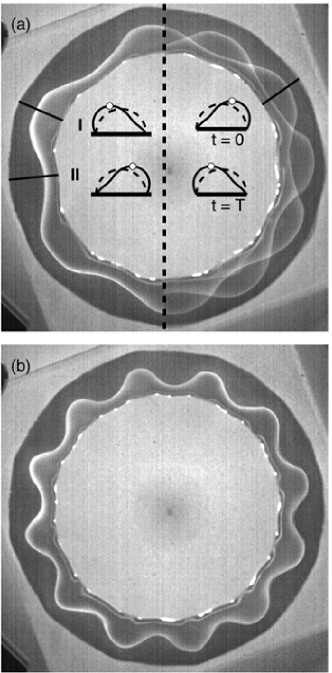
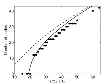
We use a systematic procedure to define the onset of surface waves. At fixed driving frequencies between 20 Hz and 65 Hz, the amplitude of oscillation is slowly increased until the fluid surface loses stability to azimuthally modulated standing waves. Distinct wave patterns are observed at half the driving frequencies. Figures 2a and b show these standing waves for two different driving frequencies. At 22 Hz (a), the wave pattern has 12 nodes (that is, 12 crossings of the wave peak along the annular mid-line). The left half of Fig. 2(a) shows a snapshot of the surface wave, whereas the right half is the image of two superimposed surface waves in different phases. In the snapshot, the cross-sectional shapes, or onset modes, of the fluid surface are shown as insets when cutting across the I and II lines. The overlapped image demonstrates that standing waves are formed at half the driving frequency (22 Hz) near the onset. Increasing the driving frequency to 36 Hz increases the number of wave nodes to 24 (see Fig. 2b). Near the onset, as the driving frequency increases, the number of nodes increases monotonically (and discretely, due to the geometry), as is shown in Fig. 3.
To describe the instability to the azimuthally modulated surface waves seen in Fig. 2, we consider an approximate model which captures the main aspects of our observations. First, we neglect viscous effects. Second, instead of using the exact semi-toroidal geometry for our calculations, we neglect the annular curvature and use a cylindrical geometry. Finally, we note that the capillary length() in our experiment is 0.3 cm slightly smaller than the radius cm, and so we expect the base state (i.e. the surface profile without azimuthal modulation) to have a flattened, temporally oscillating surface profile. Solving for the temporal evolution of the surface profile, even azimuthally unmodulated, is a nonlinear problem. Hence, for simplicity, we assume that the base state is close to a semi-circle with constant radius . Small fluctuations of the surface can then be expressed as , where is a small radial displacement deviating from . This assumption leads to a simple linear analysis for the perturbed fluid surface. A fully nonlinear, numerical treatment of the oscillations and Faraday instabilities of a driven viscous drop has been considered by James et al James03a .
A linearized form of Bernoulli equation with a velocity potential Benjamin54 in a moving frame is
| (1) | |||||
| (2) |
Here, is the oscillating body force where and are the acceleration due to a gravity and the peak acceleration of the vibrating plate, respectively. By using which neglects the nonlinear terms in the kinematic boundary condition, we can assume solutions such as
| (3) | |||||
| (4) |
where is the axial wavenumber (; is the wavelength) and is the azimuthal wavenumber (in the direction of ). Here, we assume that is small and neglect higher azimuthal modes () since we observed that is the dominate mode near the onset of surface excitation. Using the symmetry , setting the unphysical volume change term to be zero, and plugging Eqs. (3,4) into Eq. (1) yields
| (5) |
where and . The surface deformation is assumed to be of the Floquet form () where Kumar96 . For subharmonic solutions (), one gets the recursion relation:
| (6) |
where
| (7) |
and . The problem of stability of the cylindrical fluid surface is reduced to finding the eigenvalues of Eq. (6) up to the order of .
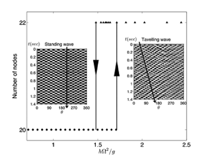
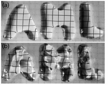
Figure 3 compares the observed patterns with the inviscid coupled linear model and the classical dispersion relation ( ). Our coupled model is in better agreement with our experimental observation than the classical dispersion relation.
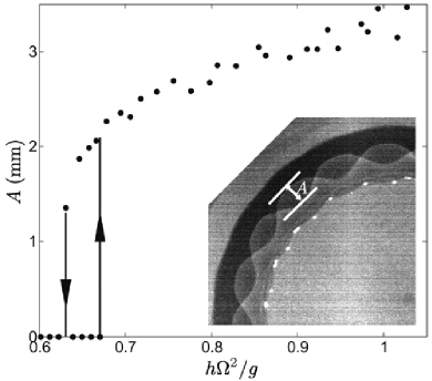
We also find experimentally that the onset of surface waves is hysteretic. Figure 4 shows the maximal displacement in the horizontal direction between standing wave peaks over the course of an oscillation, as a function of dimensionless driving acceleration , where is the amplitude of plate oscillation. Crossing a critical amplitude from below shows the sharp transition to standing wave. This bifurcation is subcritical, and at intermediate accelerations () two stable states are observed.
Figure 5 shows yet another hysteretic transition in the number of surface nodes, at a higher dimensionless acceleration. Bistable surface waves with different numbers of nodes co-exist between 1.48 and 1.71 . We find that the surface waves above this transition still oscillate at half the driving frequency, but now have more nodes and a finite drift speed (triangles). The inset images show the patterns of peaks (bright) and troughs (dark) in space-time. The arrows indicate the direction of azimuthal drift and its speed. If the acceleration is further increased to around 4 , the traveling surface waves become more spatially localized, and droplets are ejected.
Our masking technique can be used effectively to make complicated hydrophilic regions, and to investigate the dynamics of fluid volumes trapped within them. Figure 6 shows three separate fluid volumes bound within domains (the letter shapes A, M and L) of different shapes at both stable and unstable states. At fixed volume to base-area ratio of 0.16 cm3/cm2, which gives a fixed height for all shapes slightly above 0.18 cm, instability occurs at different thresholds for the different base shapes. The shape that with high aspect ratio (e.g. letter “L”) appears to have the highest threshold to instability. The top image shows these volumes at rest, where the transparent glass surface of the hydrophilic region reveals a square grid beneath. The bottom image shows the surface wave dynamics of these fluid volumes as revealed, at least in part, by the distortions of the underlying grid lines.
In this paper, we have studied the Faraday instability of a semi-toroidal water volume whose surface is initially flat in the azimuthal direction but tightly confined in the radial direction. To constrain the fluid into a tight geometric area (an annulus), the base plate is patterned with hydrophobic and hydrophilic regions. This particular geometry allows us to study the surface waves arising from a quasi-one-dimensional system with a periodic boundary condition. Systems with high aspect ratios (system size/capillary length), as used in our experiment, have not been well studied previously. Despite of the high aspect ratio, we find similar dynamics (such as the hysteretic excitation of surface waves) as found in systems with flat surfaces. The classical theory is modified to describe the observed dispersion relation in our system. The result agrees with our experimental observations. For large forcings, we observe another transition, again hysteretic, to traveling waves with an increased number of nodes. Such a transition has yet to be understood theoretically and is a subject of future investigation.
Authors thank A. Libchaber, D. Hu, and V. Rom-Kedar for helpful discussions. This work is supported by DOE Grant DE-FG02-88ER25053.
References
- (1) M. Faraday, “On a peculiar class of acoustical figures; and on certain forms assumed by groups of particles upon vibrating elastic surfaces,” Phil. Trans. R. Soc. London 121, 299 (1831).
- (2) T. B. Benjamin and F. Ursell, “The stability of the plane free surface of a liquid in vertical periodic motion,” Proc. R. Soc. London A 225, 505 (1954).
- (3) J. Miles and D. Henderson, “Parametrically forced surface waves,” Annu. Rev. Fluid Mech. 22, 143 (1990).
- (4) K. Kumar, “Linear theory of Faraday instability in viscous liquids,” Proc. R. Soc. London A 452, 1113 (1996).
- (5) E. A. Cerda and E. L. Tirapegui, “Faraday’s instability in viscous fluid,” J. Fluid Mech. 368, 195 (1998).
- (6) P. Chen and J. Viñals, “Amplitude equation and pattern selection in Faraday waves,” Phys. Rev. E 60, 559 (1999).
- (7) W. S. Edwards and S. Fauve, “Parametrically excited quasicrystalline surface waves,” Phys. Rev. E 47, R788 (1993).
- (8) L. Daudet, V. Ego, S. Manneville, and J. Bechhoefer, “Secondary instabilities of surface waves on viscous fluids in the faraday instability,” Europhys. Lett. 32, 313 (1995).
- (9) H. W. Müller, “Periodic triangular patterns in the Faraday experiment,” Phys. Rev. Lett. 71, 3287 (1993).
- (10) S. Ciliberto, S. Douady, and S. Fauve, “Investigating space-time chaos in Faraday instability by means of the fluctuations of the driving acceleration,” Europhys. Lett. 15, 23 (1991).
- (11) R. J. Lang, “Ultrasonic atomization of liquids,” J. Acoust. Soc. Am. 34, 6 (1962).
- (12) W. S. Edwards and S. Fauve, “Patterns and quasi-patterns in the Faraday experiment,” J. Fluid Mech.278, 123 (1994).
- (13) K. Kumar and K. M. S. Bajaj, “Competing patterns in the Faraday experiment,” Phys. Rev. E 52, R4606 (1995).
- (14) A. Kudrolli and J. P. Gollub, “Patterns and spatiotemporal chaos in parametrically forced surface waves: a systematic survey at large aspect ratio,” Physca D 97, 133 (1996).
- (15) R. Keolian, L. A. Turkevich, S. J. Putterman, and I. Rudnick, “Subharmonic sequences in the Faraday experiment: Departures from period doubling,” Phys. Rev. Lett. 47, 1133 (1981)
- (16) S. Douady, “Experimental study of the Faraday instability,” J. Fluid Mech. 221, 383 (1990).
- (17) J. M. Vega, E. Knobloch, and C. Martel, “Nearly inviscid Faraday waves in annular containers of moderately large aspect ratio,” Physica D 154, 313 (2001).
- (18) F. J. Mancebo and J. M. Vega, “Faraday instability threshold in large-aspect-ratio containers,” J. Fluid Mech. 467, 307 (2002).
- (19) T. B. Benjamin and J. C. Scott, “Gravity-capillary waves with edge constraints,” J. Fluid Mech. 92, 241 (1979).
- (20) C. Martel, J. A. Nicolás, and J. M. Vega, “Surface-wave damping in a brimful circular cylinder,” J. Fluid Mech. 360, 213 (1998).
- (21) M.-T. Westra, D. J. Binks, and W. van de Water, “Patterns of Faraday waves,” J. Fluid Mech. 496, 1 (2003).
- (22) H. Lamb, Hydrodynamics (Cambridge University Press,Cambridge, 1932).
- (23) C. Bisch, A. Lasek and H. Rodot, “Comportement hydrodynamique de volumes liquides spheriques semi-libres en apesanteur simulee,” J. Mec. Theor. Appl. 1, 165 (1982).
- (24) E. D. Wilkes and O. A. Basaran, “Forced oscillations of pendant (sessile) drops,” Phys. Fluids 9, 1512 (1997).
- (25) X. Noblin, A. Buguin, and F. Brochard-Wyart, “Vibrated sessile drops: Transition between pinned and mobile contact line oscillations,” Eur. Phys. J. E 14, 395 (2004).
- (26) A. Frohn and N. Roth, Dynamics of Droplets (Springer Press, Berlin, 2000).
- (27) A. J. James, B. Vukasinovic, M. K. Smith, and A. Glezer, “Vibration-induced droplet atomization,” J. Fluid Mech. 476, 1 (2003).
- (28) A. J. James, M. K. Smith, and A. Glezer, “Vibration-induced drop atomization and the numerical simulation of low-frequency single-droplet,” J. Fluid Mech. 476, 29 (2003).