Current driven rotating kink mode in a plasma column with a non-line-tied free end
Abstract
First experimental measurements are presented for the kink instability in a linear plasma column which is insulated from an axial boundary by finite sheath resistivity. Instability threshold below the classical Kruskal-Shafranov threshold, axially asymmetric mode structure and rotation are observed. These are accurately reproduced by a recent kink theory, which includes axial plasma flow and one end of the plasma column that is free to move due to a non-line-tied boundary condition.
pacs:
52.35.Py, 52.30.Cv, 52.70.Ds, 52.70.KzThe current driven kink instability is a magnetohydrodynamic (MHD) instability which affects current carrying plasmas in Nature and laboratory. The kink mode structure and stability condition are strongly dependent on the system geometry and the boundary conditions (BCs). KruskalKruskal (1954) and Shafranov Shafranov (1956) (hereafter referred to as KS) considered first the ideal MHD stability of a cylindrical plasma column with magnetic field components () using cylindrical coordinates (). For an infinitely long (equivalent to periodic axial BCs) column, they obtained a linearly unstable helical kink mode of structure when the plasma current exceeds the Kruskal-Shafranov limit
| (1) |
where and are, respectively, the radius and length of the current channel, and is the displacement of the plasma column from the equilibrium position. The KS theory has been quite successful in predicting the behavior of toroidal plasmas for which the periodic BCs yield a proper accounting for the finite length of the system. In linear systems, however, substantial deviations from KS predictions can result from different axial BCs.
The importance of the BCs has long been recognizedSolov ev (1971); Raadu (1972) and is of particular relevance to the stability of line-tied flux ropes in space physics (c.f. Ref. H. Baty (1997) and survey Ref. A.W. Hood (1992)), and astrophysical jetsD.L. Meier (2001). In recent years, there has been a renewed interest in the stability of a line-tied plasma column in laboratory devices (see Refs. I. Lanskii (1990); D.D. Ryutov (2004); C.C. Hegna (2004) and references therein). The kink stability of a plasma column with line-tied ends has been investigated in linear devices, where line-tying is attributed to the presence of highly conducting end platesBergerson (2006), and in open systems to a local discontinuity for the Alfvén velocity that forms a virtual boundary around the systemS.C. Hsu (2003); Zuin (2004).
In this Letter, we experimentally investigate the external kink instability in conditions where one end of the plasma column is line-tied to the plasma source, and the other end is not line-tied and therefore free to slide over the surface of the end-plate. The latter BC is a result of plasma sheath resistance that insulates, at least partially, the plasma from the end-plate. Compared to the line-tied case, we find significant differences in the kink mode structure and lower critical current for the onset of the kink. The axial flow velocity, the direction of the axial magnetic field, and the rotation frequency of the kink mode are all correlated. The experimental results agree with the predictions from a recent theory of the external kink instability for a slender plasma columnD.D. Ryutov (2005).
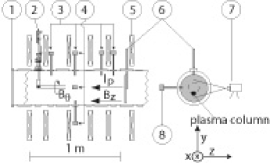
The experiments are conducted in the Reconnection Scaling Experiment (RSX) which uses electrostatic plasma guns to generate the plasmaFurno (2003). Figure 1 shows the experimental setup with a view of the plasma gun located at and radially inserted into the center of the RSX cylindrical vacuum vessel ( m length and radius m). A hydrogen arc plasma is ejected to form a cylindrical plasma column in a constant, uniform, axial magnetic field of T generated by external coils, Fig. 1-(5). Electron density and temperature have Gaussian profiles with half-maximum radius cm such that . Central electron density and temperature are m-3 and eV, and axially decrease away from the gun. The axial velocity m-1 of the plasma has been estimated by solving the momentum balance equations for dominantly axial flow constrained by experimentally measured axial gradients in pressure and density. A current is driven in the plasma by negatively biasing the gun with respect to an external anode ( m2 stainless steel plate) which is electrically isolated from the vacuum vessel. The external anode can be positioned at different axial locations m allowing the length of the current-carrying plasma column to be varied.
The MHD activity is monitored by two arrays of magnetic probes that include a total of seven coils inserted in the vacuum vessel at m to measure the azimuthal magnetic field . In the axial array, Fig. 1-(3), four magnetic probes are positioned at (top of the vessel) and axially located at and m. In the azimuthal array, Fig. 1-(4), the four magnetic probes are located at m and azimuthally equispaced by . One magnetic probe is shared by the two arrays. Signals are digitized at MHz.
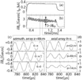
In Fig. 2(a), the time evolution of the plasma current measured at the external anode is shown for a discharge with m. The plasma current starts at when the bias is turned on (arc discharge starts at ms) and after s reaches a stationary phase which lasts for ms. The total plasma current A during the stationary phase is determined by the bias voltage and can be varied in the range kA. Figure 2(b) shows the time evolution of as measured by the magnetic probe located at m, .
For an expanded time window during the stationary phase, measurements of the perturbed azimuthal magnetic field from the azimuthal, Fig. 2(c), and the axial, Fig. 2(d), arrays of probes show oscillations with azimuthal periodicity at the frequency kHz. These oscillations are observed when exceeds a current threshold (see below), but are not detectable for . The observed instability growth time s is of the order of the axial Alfvén time.
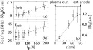
The azimuthal structure is consistent with a plasma column rotating as a rigid body at frequency . The phase of the signals from the axial array increases linearly along the direction, Fig. 2(d), indicating a rotating helical current channel. The kinked deformation is a right(left) handed helix if , as expected from a paramagnetic kinkS.C. Hsu (2003). The direction of rotation reverses when reversing the external magnetic field . In both cases, the mode rotation is such that the helix always screws into the external anode. Both the rotation frequency and the average amplitude of the oscillations at the dominant frequency during the stationary phase scale linearly with as shown in Fig. 3(a,b) where the plasma current is varied in the range A A for a plasma column length m. The plasma current corresponding to the limit corresponds to the kink stability threshold which for these data is A. The rotation frequency at the stability threshold is kHz, Fig. 3(b).
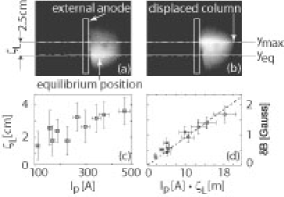
Figure 3(c) shows the axial structure of the mode close to criticality for . While a line-tied BC holds at the gun, the large amplitude of the mode at m can only occur if the plasma slides over the external anode and is therefore not line-tied. This is confirmed by images of the plasma column at the external anode as shown in Fig. 4. emission is imaged with a Cooke DiCam Pro intensified cameraHemsing et al. (2005) that views the external anode edge perpendicularly to the axis, Fig. 1-(7). In Figs. 4(a-b), two fast-gated ( ns gate Alfvén time) images show respectively the plasma column in the equilibrium position and at the maximum displacement during the rotation.
The observed sliding of the plasma column over the external anode surface is not consistent with a line-tied BC, which might be presumed at the external anode for time scales less then a s resistive diffusion time. Deviations from line-tying may appear if the plasma is insulated from the external anode by a finite plasma sheath resistance. The degree of insulation is measured by the ratio of the Alfvén transit to inductive decay times of the currentD.D. Ryutov (2005). We estimate from the formula where , and is the plasma frequency (derivation in Ref. D.D. Ryutov (2005)) for typical plasma parameters cm, eV, m-3, . For the present experiments, we conclude that and the plasma is insulated from the conducting boundary by finite sheath resistance. Ryutov and coauthors D.D. Ryutov (2005) have shown that for the BC can be formulated as where with Cartesian complex displacement . In the following, we will refer to this condition as to perfect non-line-tying (PNLT) BC and we will show that it holds at the external anode, after using an equivalent condition that can be directly compared with experimental data.
With a thin plasma column approximation () and assuming that is the equilibrium position, the Cartesian components of the perturbed magnetic field at can be expressed as ). Using the PNLT condition, in the vicinity of the external anode the perturbed magnetic field can be expressed as
| (2) |
where .
We use magnetic measurements combined with images near the external anode to test Eq. (2), equivalent to the PNLT condition. Images such as those in Fig. 4(a,b) determine the maximum displacement and equilibrium positions of emissivity along a line parallel to the external anode surface and axially spaced m in front of it. The image in Fig. 4(b) is synchronized to a magnetic probe at the same axial location but azimuthally separated by to provide the position of maximum column displacement. In Fig. 4(c), the displacement is shown for a series of discharges with 100 A A. In Fig. 4(d), the magnetic perturbations (, ) are measured at m and cm in front of the external anode using a bi-dimensional magnetic probe. In Fig. 4(d), the experimental data show excellent agreement with the PNLT predicted scaling in Eq. (2) (shown as a dashed line). We therefore conclude that the PNLT BC applies to the external anode.
For a PNLT BC at and with axial plasma flow velocity , the eigensolution for the MHD equation of motion (Eq. (57) in Ref. D.D. Ryutov (2005)) is with axial wave numbers where is the Alfvén Mach number, and is calculated using the average density . In Fig. 3(c), the axial structure of from experimental data for (squares) and from the theoretical eigensolution (dot-dashed line) are compared. The good agreement suggests a robustness of the eigensolution for slightly super-critical regimes. The total axial phase shift at criticality (not shown here) is also consistent within the experimental uncertainties with the expected eigensolution for Mach numbers in the range .
The critical current in this case is
| (3) |
showing that the kink mode is unstable at half the KS current for vanishing flow and smaller currents when flow exists. The eigenfrequency at the criticality has a finite real component
| (4) |
The perturbed plasma column rotates at frequency , constant along the column. The rotation is driven by axial plasma flow from the gun to the external anode along the helically-perturbed column as well as a Doppler shifted , such that the helix always screws into the external anode, consistently with the experimental observations.
To investigate the applicability of Eqs. (3) - (4), figure 5 shows (a) the critical current and (b) the rotation frequency at the criticality as a function of the inverse column length which is in agreement with a predicted linear scaling.
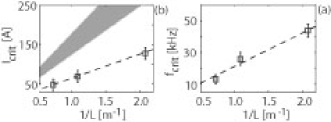
The system comprising Eqs. (3) -( 4) provides a theoretical relationship between , , , and the average plasma density (or Alfvén speed). This was solved using experimental measurements of the electron density profile at criticality together with deduced scalings [A] and [Hz] from the data in Fig. 5. We obtained a radius cm which is in agreement with the experiment (see Fig. 6) and Mach number . The corresponding axial flow velocity m-1 is also consistent with our independent estimate. In Fig. 5, predictions from KS theory using the computed are compared to the experimental data.
For the external kink, the radius is expected at the position where conductivity, magnetic diffusion time, and axial current density are negligibly small. This is tested using profile measurements at the criticality. Figure 6 shows a Bennet profile least-squares fit of at the instability threshold, as obtained from azimuthal magnetic field measurements at m for m. The previously determined radius cm is located at the edge of the profile where . Similar conclusions follow from the magnetic diffusivity, derived from the measured electron temperature profile and the observed instability growth time .
It should be emphasized here that the measurements in this Letter only characterize the global structure of the external kink mode. Although some of the observations (e.g., axial structure and rotation frequency of the mode) show some resemblance with measurements of internal drift-Alfvén waves in finite- plasmas with axial currentTang et al. (1976), additional internal measurements will be needed to investigate the presence of these waves in our experiment.

In summary, we have presented first experimental results for the current driven kink instability in a plasma column with one free end that is not line-tied to its boundary due to a finite sheath resistance. Mode structure and instability threshold are significantly different from predictions from the Kruskal-Shafranov theory and are accurately reproduced by a recently developed kink theory. The finite rotation of the mode, which is also observed in other laboratory devicesZuin (2004); Bergerson (2006), is due to the plasma flow along the helically kinked plasma column.
Though not addressed here, the effect of a non line-tied end should be important for the relaxing kinked plasma column. A destabilizing force coexists with a stabilizing curvature force due to axial field line bending. The free end allows shifts with reduced curvature and restoring force possibly resulting in a helical saturated state of larger displacement than the line-tied case. Numerical simulations are being implemented for the non-linear evolution of the kink mode.
Support by Los Alamos Laboratory Directed Research and Development - Exploratory Research program, and Associazione Sviluppo Piemonte for S. Abbate is gratefully acknowledged.
References
- Kruskal (1954) M. Kruskal and J. Tuck, Proc. R. Soc. A 245, 222 (1958).
- Shafranov (1956) V. D. Shafranov, At. Energ. 5, 38 (1956).
- Solov ev (1971) L. S. Solov’ev, Sov. At. Energy 30, 14 (1971).
- Raadu (1972) M. A. Raadu, Sol. Phys. 22, 425 (1972).
- H. Baty (1997) H. Baty, Astron. Astrophys. 318, 621 (1997).
- A.W. Hood (1992) A. W. Hood, Plasma Phys. Contr. Fus. 34, 411 (1992).
- D.L. Meier (2001) D. L. Meier, S. Koide and Y. Uchida, Science 291, 84 (2001).
- I. Lanskii (1990) I. M. Lanskii and A. I. Shchetnikov, Sov. J. Plasma Phys. 16, 322 (1990).
- D.D. Ryutov (2004) D. D. Ryutov, R. H. Cohen and L. D. Pearlstein, Phys. Plasmas 11, 4740 (2004).
- C.C. Hegna (2004) C. C. Hegna, Phys. Plasmas 11, 4230 (2004).
- Bergerson (2006) W. F. Bergerson, et al., Phys. Rev. Lett. 96, 015004 (2006).
- S.C. Hsu (2003) S. C. Hsu and P. M. Bellan, Phys. Rev. Lett. 90, 215002 (2003).
- Zuin (2004) M. Zuin, et al., Phys. Rev. Lett. 92, 225003 (2004).
- D.D. Ryutov (2005) D. D. Ryutov, et al., Phys. Plasmas 13, 032105 (2006).
- Furno (2003) I. Furno, et al., Rev. Sci. Instrum. 4, 141 (2003).
- Hemsing et al. (2005) E. Hemsing, I. Furno and T. Intrator, IEEE Trans. Plasma Sci. 33, 448 (2005).
- Tang et al. (1976) J. T. Tang, et al., Phys. Rev. Lett. 34, 70 (1975); J. T. Tang and N. C. Luhman Jr., Phys. Fluids 19, 1935 (1976).