The Role of Quantum Vacuum Forces in
Microelectromechanical Systems
Abstract
The presence of boundary surfaces in the vacuum alters the ground state of the quantized electromagnetic field and can lead to the appearance of vacuum forces. In the last decade, landmark measurements of the vacuum stress between conducting uncharged parallel plates. Recently the first micromachined MEMS (microelectromechanical system) device was fabricated that utilizes the Casimir force between parallel plates. The force dependence allows the device to serve as a highly sensitive position sensor. The are many other examples of quantum vacuum forces and effects besides the well known parallel plate Casimir force. Here we discuss potential roles of quantum vacuum forces and effects in MEMS systems and other systems. With the growing capability in nanofabrication, some of the roles may be actualized in the future. Because of the computational complexity, no theoretical results are yet available for a number of potentially interesting geometries and we can only speculate.
pacs:
12.20.-m, 42.50.LcLABEL:FirstPage1 LABEL:LastPage#12
I Introduction
Zero-point field energy density is a simple and inexorable property of a quantum field, such as the electromagnetic field, which is a representation of the Lorentz group of transformations of special relativity. For a quantum field, the canonical position and momentum variables do not commute and consequently the lowest state of the field has a non-zero energy, just as the ground state of a quantum mechanical harmonic oscillator is non-zero. For the electromagnetic field, if we assume the shortest wavelength photon to be included in the ground state spectrum has the Planck length of 10-35 m, then the predicted quantum vacuum energy density is enormous, about J/m3 or, in terms of mass, g/cm Such an enormous energy density is clearly a puzzling embarrassment to physicists, who for years routinely discarded this nearly infinite result in renormalization procedures.
However, there are measurable consequences of the zero point energy which arise because the ground state vacuum electromagnetic field has to meet the usual boundary conditions for the electromagnetic field. It is the effect of boundaries on the vacuum field that leads to the appearance of vacuum stresses, so called Casimir forces.
The term ”Casimir force” most commonly refers to the attractive vacuum force per area (pressure) that exists between two parallel, infinite, uncharged, perfectly conducting plates separated by a distance plunienreview bordag
| (1) |
where This force arises from the change in energy density from the free field vacuum density that occurs between the parallel plates:
| (2) |
This attractive force ,which is normal to the surface, arises because the surfaces change the mode distribution of the ground state quantized electromagnetic field. In the region between two parallel perfectly conducting plates, no modes with wavelengths larger than twice the separation can exist. We can also view this force as arising from radiation pressure, the transfer of momentum from the vacuum to the surfacesmilonniradpressure . The Casimir effect was first predicted in 1948, but was not measured accurately until the last few yearsmohideenroy lamoroux . Corrections for finite conductivity and surface roughness have been developed for the parallel plate geometry, and the agreement between theory and experiment is now at the 1% level or better for separations of about 0.1-0.7 realplatesmoh . In actual practice, the measurements are most commonly made with one surface curved and the other surface flat, and using the proximity force theorem to account for the curvature. This experimental approach eliminates the difficulties of trying to maintain parallelism at submicron separations. Mohideen and collaborators have made the most accurate measurements to date in this manner, using an AFM (Atomic Force Microscope) that has a metallized sphere about 250 in diameter attached to the end of a cantilever about 200 long, capable of measuring picoNewton forces. The deflection of the sphere is measured optically as it is moved close to a flat metallized surfacemohideenroy . The more difficult measurement between two parallel plates has been made and shown to give results that are consistent with theorybressi . Measurements of the force between two parallel surfaces each with a small (1 nm) sinusoidal modulation in surface height, have showed that there is a lateral force as well as the usual normal force when the modulations of the opposing surfaces are not in phase chenlateral . Recent measurements have confirmed the predictions, including effects of finite conductivity, surface roughness, and temperature, uncertainty in dielectric functions, to the 1-2% level for the range from 65-300 nmmohideen2 . There is a small uncertainty in the temperature corrections, particularly at low temperatures temp .
Casimir forces occur for all quantum fields and can arise from the presence of surfaces as well as choices of topology of the space. Initially Casimir forces for plane surfaces were obtained by computing the change in the vacuum energy with position. Two decades after Casimir’s initial predictions, a method was developed to compute the Casimir force in terms of the local stress-energy tensor using quantum electrodynamicsbrownmaclay . Many innovations have followed. Several approaches to computing electromagnetic Casimir forces have been developed that are not based on the zero point vacuum fluctuations directly. These approaches appeal to scientists who are uncomfortable with the quantum electrodynamical model of energy in empty space. In the special case of the vacuum electromagnetic field with dielectric or conductive boundaries, various approaches suggest that Casimir forces can be regarded as macroscopic manifestations of many-body retarded van der Waals forces, at least in simple geometries with isolated atomspwm , Power . Casimir effects have also been derived and interpreted in terms of source fields in both conventional pwm and unconventional schw quantum electrodynamics, in which the fluctuations appear within materials instead of outside of the materials. Lifshitz provided a detailed computation of the Casimir force between planar surfaces by assuming that stochastic fluctuations occur in the tails of the wavefunctions of atoms that leak into the regions outside the surface, and can lead to induced dipole moments in atoms in a nearby surface, which leads to an a net retarded dipole-induced dipole force between the planar surfaceslifshitz . These various approaches differ in how they visualize the fluctuations of the electromagnetic field, but give consistent results in the few cases of simple geometries which have been computedmaclayandmilonni . It may be that these diverse approaches will display differences for computation of geometries with curvature, or for computations of the forces between separated, curved surfacesmaclaysqueezed .
Parallel plate Casimir forces go inversely as the fourth power of the separation between the plates. The Casimir force per unit area between perfectly conducting plates is equivalent to about 1 atm pressure at a separation of 10 nm, and so is a candidate for actuation of MEMS (MicroElectroMechanical Systems). In MEMS, surfaces may come into close proximity with each other, particularly during processes of etching sacrificial layers in the fabrication process. In 1995 the first analysis of a dynamic MEMS structure that used vacuum forces was presented by Serry et alserry . They consider an idealized MEMS component resembling the original Casimir model of two parallel plates, except that one of the plates is connected to a stationary surface by a linear restoring force and can move along the direction normal to the plate surfaces. The Casimir force between the two plates, together with the restoring force acting on the moveable plate, results in a bistable system with two equilibrium separtions. The larger separation is a stable equilibrium and the smaller one is unstable, leading to the collapse of the movable surface into stationary plate. The analysis demonstrates that the Casimir effect could be used to actuate a switch, and might be responsible in part for the “stiction” phenomenon in which micromachined membranes are found to latch onto nearby surfaces. If the movable surface is vibrating, then an “anharmonic Casimir oscillator” (ACO) results.
To explore stiction in common MEMS configurations, Serry et al computed the deflection of membrane strips and the conditions underwhich they would collapse into nearby surfacesserry2 . Measurements were done by Buks et al on cantilever beams to investigate the role of Casimir forces in stictionbuk . An experimental realization of the ACO in a nanometer-scale MEMS system was recently reported by Chan et al chan . In this experiment the Casimir attraction between a 500 m-square plate suspended by torsional rods and a gold-coated sphere of radius 100 m was observed as a sharp increase in the tilt angle of the plate as the sphere-plate separation was reduced from 300 nm to 75.7 nm. This “quantum mechanical actuation” of the plate suggests “new possibilities for novel actuation schemes in MEMS based on the Casimir force” chan . In a refinement of this experiment, a novel proximity sensor was demonstrated in which the plate was slightly oscillated with an AC signal, and the deflection amplitude observed gave an indication of the precise location of the nearby spherechan2 . A measurement using a similar torsion oscillator was recently reported using gold on the sphere and chromium on the platedecca .
MEMS currently employed in sensor and actuator technology generally have component separations on the order of microns, where Casimir effects are negligible. Smaller distances between MEMS components are desirable in electrostatic actuation schemes because they permit smaller voltages to be used to generate larger forces and torques. Casimir effects will be of increasing significant in microelectromechanical systems (MEMS) as further miniaturization is realized serry .
II Limitations of Current Theoretical Calculations of Vacuum Forces
The parallel plate geometry (and the approximately equivalent sphere-plate geometry or sphere-plate with small deviations geometry) is essentially the only geometry for which experimental measurements have been conducted and the only geometry for which the vacuum forces between two separate surfaces (assumed to be infinite) have been computed. Vacuum forces are know to exist in other experimental configurations between separate surfaces, but rigorous calculations based on QED (quantum electrodynamics) are very difficult and have yet to be completedmaclaysqueezed . Since it is experimentally possible to measure forces between various separate surfaces, with the improvement in experimental techniques, theoreticians may soon see the need for such computations.
Calculations of vacuum stresses for a variety of geometric shapes, such as spheres, cylinders, rectangular parallelepipeds, and wedges are reviewed in plunienreview bordag miltonbook . In general, calculations of vacuum forces become very complex when the surfaces are curved, particularly with right angles. Divergences in energy appear, and there are disagreements about the proper way to deal with these divergencesDeutsch . The material properties, such as the dielectric constant and plasma frequency of the metal and the surface roughness also affect the vacuum forces. In addition, in the usual calculations only a spatial average of the force for a given area for the ground state of the quantum vacuum field is computed, and material properties, such as binding energies, are ignored, a procedure which Barton has questioned recentlybartonboston barton2 maclaypra .
Computation has shown that the vacuum stress on a spherical metal shell, a cubical shell, or a solid dielectric ball is a repulsive uniform force, or directed outward. Because of the very special nature of the parallel plate geometry and the high degree of symmetry of the cube and sphere, it is not reliable to make generalizations about the behavior of vacuum forces based on these special geometries. The vacuum forces on the faces of conductive rectangular boxes or cavities show very different features compared to those of the parallel plate, the cube, and the sphere. For a rectangular parallelepiped cavity, the total force on a given face (the differential force integrated over the entire face) can be positive, zero, or negative depending on the ratio of the sides of the boxmaclaypra ambjorn carlosrectangular lukosz . In fact there are cavities that have zero force on two sides and a positive or negative force on the remaining side. There are boxes for which the change in the vacuum energy is negative (or positive) and the forces on some walls are attractive while the forces on the remaining walls are repulsive. Indeed it is difficult to get an intuitive picture of the meaning of these results.
From a technological viewpoint, it would be useful to be able to generate repulsive vacuum forces as well as attractive vacuum forces. From a fundamental viewpoint, it is unclear how one can have a repulsive force in vacuum if the force can be correctly modeled as a dipole-induced dipole force. Thus there is great interest in measuring the vacuum forces in different geometries that are predicted to be repulsive. However, there is no easy way to measure vacuum forces on spheres or rectangular cavitiesmaclayitamp . One might consider applying a stress to the spherical shell, and observe the deformation. This is a difficult experiment since the sphere would probably have to be submicron in diameter for the Casimir force to be large enough to be measurable. Further, the deflection measured would depend on the properties of the material of which the sphere was made, and such properties are not included in the usual calculations of the Casimir forcebarton2 . Alternatively one might contemplate cutting a sphere in half, and measuring the force between the two hemispheres using an Atomic Force Microscope. However, the question arises: If we cut a spherical cavity into two hemispheres, will we find a repulsive force between the two separate surfaces? Or will an attractive force between the edges dominate? No computations have yet been done for this situation for real materials. For optically thin materials Barton shows the net force will be attractivebartonboston barton2 .
Vacuum forces computed for a perfectly conducting cube with thin walls are also repulsive or outward, and experimentalists have the same conundrum regarding the meaning of this calculated vacuum force. To measure the force one might imagine freeing one face of the cube, and then moving it very slightly normal to its surface, in the spirit of the principle of virtual work dE=-Fdx. Unfortunately no one has computed the force between a cube with one side removed and a nearby surface which is parallel to the missing face. We have attempted to measure the force between an array of open cavities (wall thickness about 150 nm, cavity width about 200 nm) and a metallized sphere 250 m in diameter on an AFM cantilever, and to date have only observed diminished attractive forcesaiaarepexp .
Another limitation of the calculations to date for the rectangular cavity, is that only the total force on each face is computed. The differential vacuum stress in not uniform on each wall, and, in order to avoid issues with divergences, the differential force is integrated over the face. How these nonuniformities might affect experiments is unknown.
The sign of the Casimir force depends on the magnetic and electric properties of the materials. If it were possible to arbitrarily choose material properties, repulsive forces could be obtained in a parallel plate geometry, for example, by choosing one plate to be a perfect conductor ( and the other plate as a perfect magnetic material ( for all frequencies, real and imaginary, with a vacuum in betweenkenneth . Other choices have also been suggested, however, none have been implemented experimentally, and it appears they all violate fundmental requirements about and for real materials that arise from causality.conditionssantos . It has been suggested but not verified that in curved space-time, atoms in certain intense electric fields may exhibit repulsive forcespintocurved .
III Vacuum Force Actuated MEMS Systems
We consider a variety of systems whose function is based on existing calculations of the properties of the ground state of the quantum vacuum. Several different potentially interesting applications are considered in maclayandmilonni No experimental investigations have yet been conducted on most of these systems.
III.1 Structures with Parallel Plates
We consider the forces and energy balance in several simple structures with: 1. moving parallel plates; 2. moving plates inserted in rectangular cavities, and 3. pistons moving in rectangular cavitiesstaif00 .
 |
 |
 |
III.1.1 Moving Parallel Plates
Consider two conducting, overlapping , square, parallel plates, a distance on each side, that are a distance apart, with . If we allow the upper plate to approach the lower (fixed) plate quasistatically, then the attractive force does positive mechanical work during this reversible thermodynamic transformation. We are neglecting edge effects by assuming that the force is proportional to the area. During the transformation, the vacuum energy between the plates will be reduced, conserving the total energy in the system. If the separation decreases from to , then the energy balance is
| (3) |
If we then separate the plates quasistatically, letting increase from to , we do work on the system to restore it to its initial state. Over the entire cycle no net work is done, and there is no net change in the vacuum energy.
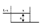
Consider an alternative cycle that several investigators have proposed in order to extract energy from the vacuum fluctuations: After the plates have reached the point of minimum separation, slide the upper plate laterally until it no longer is opposite the lower plate , eliminating the normal Casimir force, then raise the upper plate to its original height, and slide it laterally over the lower fixed plate . Finally we allow the plates to come together as before, extracting energy from the vacuum fluctuations and doing mechanical work. If no energy were expended in moving the plate laterally, then this cycle would indeed result in net positive work equal to the energy extracted from the vacuum. Although no one has yet computed in detail the lateral forces between offset finite parallel plates, it is highly probable that such forces are not zero, and that no net extraction of energy occurs for this cycle. We can verify this by a simple approximate calculation. We do know that the vacuum energy is not altered by a single infinite conducting plate dewitt . If we neglect Casimir energy “fringing fields,” and assume that the energy density differs from the free field density only in the region in which the two square plates overlap a distance , where (see Fig. 1a), then we can compute the lateral force between the two plates using the conservation of energy (principal of virtual work):
| (4) |
This constant attractive lateral force tends to increase or pull the plates towards each other so they have the maximum amount of overlap. In fact, the positive work done to move one plate laterally a distance exactly cancels the work extracted from the vacuum fields in moving the plates from a large separation to a distance apart, so there is no net change in total energy (mechanical plus field) in the complete cycle, as expected. The normal Casimir force between these plates when they are directly opposite, with complete overlapping (), is times larger than the constant lateral force given by Eq. (4).
III.1.2 Parallel Plate Comb Structure
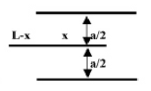
Consider the case of two fixed, square (), parallel plates separated by a distance a, with a third moveable plate that slides in between the two parallel plates, separated by a distance from each plate (Fig. 1b). If we neglect vacuum energy “fringing fields”, as before, that the vacuum energy is different from zero only in regions between directly opposing plates, and we can compute the lateral force on the moveable plate in the middle as minus the derivative of the vacuum energy. The energy, as a function of the overlap x of the fixed and moveable plate, is
| (5) |
which yields a lateral force equal to
| (6) |
This force is times the normal Casimir force between the plates separated by a distance , a factor which is typically much less than one. For a device with micrometer, mm, the lateral force would be an easily measurable 31 nanoNewtons. This structure is analogous to the electrostatic comb drive that is used extensively in MEMS (microelectromechanical systems) devices. One key operational difference between the Casimir and electrostatic drives is that the Casimir force drive always yields an inward or attractive force, whereas the voltage on the electrostatic comb drive can be reversed in polarity, reversing the direction of the force. Another difference is that the Casimir force comb drive requires no electrical actuation.
III.1.3 Inserting Parallel Plates into Rectangular Cavities
The mechanical behavior of the parallel plate comb configurations is determined by the negative energy density that arises when . If we consider cavities that have dimensions in orthogonal directions that are within about a factor of about 3 of each other, then we can have regions with positive or negative energy density and can obtain both attractive and repulsive average forces on sliding plates.
For example, consider a rectangular cavity formed from conductive plates. Imagine that the side of length is constructed so that we can slowly insert an additional plate (assumed to have zero thickness) in a direction normal to the direction, dividing the cavity into two identical rectangular regions with sides . By the conservation of energy we can compute the average force required to insert this moveable plate. If we assume that no energy is dissipated within the perfectly conducting plate during insertion and that the vacuum energy density is altered only in the region within the cavity as we insert the plate, then the change in vacuum energy is equal to minus the average force present during insertion of the movable plate times the distance . Defining as the vacuum energy of a rectangular cavity with sides , we can express the average force as
| (7) |
Depending on the ratio of we can obtain positive, zero, or negative average forces. As discussed by maclaypra , the energy for a rectangular cavity is a homogeneous function of the dimensions: . With this information we can evaluate the average force for several examples. Assume , then by numerical computation we have the final state , and for the initial state . For this geometry, the mean force is therefore positive, which means the vacuum field resists the insertion of the sliding plate:
| (8) |
For a micrometer, the force is about 2.5 picoNewtons, which is near the current limit of measurability with an AFM. Inserting a plane into a cavity is an interesting operation since it does manifest, at least in theory, a repulsive force on the movable element. Note that we have only computed an average force during insertion. This is consistent with the theoretical computations which only provide the average vacuum energy density of the cavity.
III.1.4 Rectangular structures with a moveable piston
Consider a rectangular conductive cavity with a moveable, infinitely thin, perfectly conducting piston that moves along the direction, dividing the cavity into two regions, each with its contribution to the total vacuum energy. We assume the piston is normal to the direction (Fig. 1c). We can then numerically compute the total vacuum energy of the structure as a function of the distance between the piston and one end of the cavity. From our definition of , and the definition , we have
| (9) |
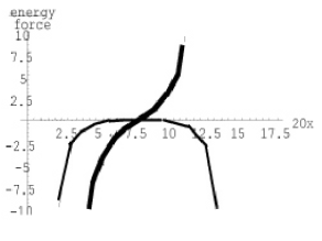
where we have assumed the energies are additive. If we differentiate this equation with respect to , we obtain an expression for the force due to the vacuum stresses on the moveable plate. Consider an example in which , so . Figure 2 shows the dimensionless energy and force respectively and as functions of . For values of near the center (), the force on the piston is approximately directly proportional to , and the energy is approximately a negative parabola with negative curvature. A small deflection from leads to a force causing an increased deflection. Thus Figure 2 shows the state of the system with the piston near the center is unstable: the piston would be pushed to the closest end of the cavity. More detailed calculations, in which the divergences were not dropped, have shown that all divergences exactly cancel for this piston geometry hertzberg .
However, if we include the restoring force on the piston that arises from the small deflection of a deformable membrane as given by Hooke’s Law, then this configuration might become stable if the material force constant exceeds that for the Casimir force. Of course, once material properties are included, the theoretically computed vacuum forces may be changed. In any event, these results suggest the intriguing possibility of making a structure that might displays simple harmonic motion for small displacements by employing two adjacent cubical cavities, with a common face that can be deflected.
III.2 Vibrating Cavity Walls in MEMS Cavities
The unexpected behavior of forces on the walls of a rectangular cavity mentioned previously allows us to model a cavity with dimensions such that a wall vibrates in part due to the vacuum stressmaclaysqueezed . For example, a cavity that is 2 long, 0.1 wide, and about 0.146 deep will have zero force on the face normal to the 0.146 direction. The zero force corresponds to an unstable energy maximum. Thus a deflection inward leads to an increasing inward (attractive) force, and, conversely, any deflection outward (repulsive force) leads to an increasing outward force. This potential is akin to a harmonic oscillator, except the force is destabilizing () rather than stabilizing (). If we assume that the box is made of real conductive materials, then there will be a restoring force due to the material. If we include the restoring force that arises from the small deflection of a deformable membrane as given by Hooke’s Law, then this configuration might become stable if the material force constant exceeds that for the Casimir force (Fig. 3).
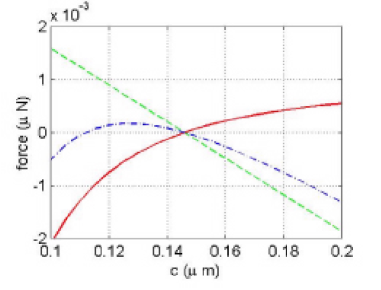
These results suggest the intriguing possibility of making a structure that displays simple harmonic motion for small displacements with a frequency that depends on the difference of the material force constant and the vacuum force constant. The face of a box of the proper dimensions may oscillate under the mutual influence of the vacuum force and the Young’s modulus of the material (Fig. 4a). The oscillations would be damped due to the non-ideal properties of the material and the friction with the environment (Fig. 4b). A zero point oscillation of the cavity wall would be expected. The energy in the lowest mode would be modified by the temperature.
III.3 Comment on the Exchange of Energy with the Quantum Vacuum
If QED predicts a large energy density in the quantum vacuum, is there some way to make use of this vast energy? In order to maintain the conservation of energy, all forms of energy, including vacuum energy, must be included. Thus from the scientific viewpoint, the answer seems clear that it is possible to transduce vacuum energy into, for example, mechanical energy. However, the process as currently understood does not appear to have any practical value. No one has conceived of a system in which energy can be extracted in a closed cycle from the vacuum. All that can be done is extract energy in a single operation. To illustrate, consider, an arrangement of two perfectly conducting, uncharged, parallel plates in a vacuum as an energy source. The Casimir energy at zero degrees Kelvin between plates of area , separated by a distance is:
| (10) |
If we allow the plates to move from a large initial separation to a very small final separation then the change in the vacuum energy energy between the plates is approximately:
| (11) | ||||
| (12) |
The attractive Casimir force has done work on the plates, and, in principal, we can build a device to reversibly extract this energy and use it. At the end of the motion (), the energy of the electromagnetic field of the quantum vacuum between the plates has been reduced by the amount of the work done, so, as is necessary, the total energy is conserved. In practice the closest distance in separation is about a nanometer due to surface roughness. However, in practice, the forces are piconewtons over a distance of nanometers, so very little useful energy is extracted. In addition, once the plates have moved together, and the energy has been extracted, one has to do the same amount of work to separate the plates and return them to the initial positions since this is a conservative systemstaif00 .
From a more fundamental perspective, utilizing energy of the quantum fluctuations of the electromagnetic field does not appear to directly violate known laws of physics according to the work of Forward, and Cole and Puthofff, however improbable or impossible such a development might seem at first consideration forward coleandputhoff . Forward showed that it is possible to conceive of a device, a foliated capacitor, in which one could extract electrical energy from the quantum vacuum to do work. The energy is extracted as the portions of the capacitor that repel each other due to electrostatic forces come together under the influence of the Casimir forceforward . Cole and Puthoff used stochastic electrodynamics to examine the process of removing energy from the vacuum fluctuations at zero temperature from the viewpoint of thermodynamics and showed there is no violation of the laws of thermodynamicscoleandputhoff . In the same spirit, Rueda has suggested that very high energy particles observed in space may derive their kinetic energy from a long term acceleration due to the stochastic vacuum fieldrueda . In a careful analysis, Cole has shown that this process of energy transfer from the vacuum field to kinetic energy of the particles does not violate the laws of thermodynamicscolethermod . In stochastic electrodynamics one treats the vacuum fluctuations as a universal random classical electromagnetic field. A formal analogy exists between stochastic electrodynamics and quantum electrodynamics: the field correlation functions in one theory are related to the Wightman functions in the other theoryboyer .
III.4 Vacuum Forces on Particles
As we have mentioned, the parallel plate vacuum forces have been extensively measured and calculated, and even utilized in a sensitive position sensor. Theoretical forces for geometries with moveable parallel plates, and rectangular cavities have been explored. The question arises: what other manifestations of vacuum forces, aside from stiction effects, might be of technological interest as the dimensions of MEMS devices are reduced? We mention a few examples. The first has to do with forces on charged or polarizable particles in the vacuum. The electromagnetic field of the ground state of the quantum vacuum shares the properties of the fields arising from excited states of the electromagnetic field, when real photons are present. Whenever there is an inhomogeneous vacuum energy density, there will a net force on a polarizable neutral particle given by Local changes in mode density and therefore vacuum energy density are induced by the presence of curved surfaces, and, depending on whether the curvature is positive or negative, the force between the surface and the particle may be repulsive or attractive Deutsch . The simplest example of a surface altering the vacuum modes is a perfectly conducting, infinite wall. The change in the vacuum field energy due to the wall produces in this case the well-known Casimir-Polder interaction: for sufficiently large distances from the wall. The interaction potential is , where is the static polarizability of the (ground-state) atom. This effect has been accurately verified in the elegant experiments of Sukenik et al in which he measured the deflection of an atomic beam near a surfacesuk . In this experiment, the particles are actually passed between the surfaces of a wedge consisting of two conducting planes that intersect at an angle radians. The stress-energy tensor is not constant in this region, as it is between two parallel plates, but increases as one moves closer to the point of intersection, at which there is a singularity. In the experiment, only the effect of the force approximately normal to the surfaces was measured. As one might expect, there is also a radial force on a particle at a distance and at an angle from the intersection that tends to accelerate the particle toward the intersection provided the static polarizability is positivebrevik :
For the case of we have a particle near a plane and recover the usual Casimir-Polder force. The tangential force in the direction vanishes along this midline. Note that there would be a torque on a permanent dipole in this wedge.
There are many geometries for which the stress-energy tensor has not been computed as a function of position, and we do not know what the forces on a charged or polarizable particle in the vacuum might be. Consider for example, the forces on a particle within a closed rectangular cavity, where the kinetic energy of the particle is much less than the change in vacuum energy due to the surfaces. Very near any surface, away from edges and other walls, one might expect the particle to experience the usual Casimir-Polder force. In other regions of the cavity, the forces are not know since calculations of the stress-energy tensor have not been done without averaging over the entire volume. What is the equilibrium state of a group of atoms or particles in a region of altered vacuum energy? For example, assume we have a number of particles in a metal sphere or a metal box in which the vacuum modes have been altered from the free field modes. What is the equilibrium distribution of these particles? Since there is a non-homogeneous vacuum field, the particles will experience forces. Will there be some vacuum damping that gives them a terminal velocity? Will the particles congregate in a region of the lowest energy? Will they bounce off the walls and give some kind of force on the walls. Are these vacuum forces negligible, except at very low temperatures? The motion of one particle inside a box or sphere would be interesting. Does the interaction provide a window into vacuum energy so that we can make two reservoirs to operate an engine?? If a hole is put in one of the sides of the box, what happens? There is one calculation that suggests that very high energy particles observed in space may derive their kinetic energy from a long term acceleration due to the stochastic vacuum fieldrueda .
III.5 Systems with Torques
Consider the conditions for which we would expect a medium, such as a dielectric slab, to experience a torque in the vacuum. If we view the origin of a vacuum torque as the transfer of the angular momentum of zero-point photons to the medium, then it is clear that to have a torque we need to have a geometrical configuration in which the vacuum energy depends on the angular orientation of the medium. This requirement cannot be met with a single object, even if it is not isotropic. However, two plates separated by a distance that are birefringent would break the rotational symmetry of the vacuum and be expected to experience a torque. This torque has indeed been calculated, and compared to the attractive Casimir force between the platesenk . From dimensional grounds the torque between two thick plates (thicknessseparation) of area goes as where Enk has derived an expression for the dimensionless number which is determined by the square of the difference of the refractive indices, and has a typical value of about The torque, which appears measurable, varies as , where is the angle between the two optic axes. The dielectrics tend to rotate in opposite directions so the total angular momentum transfer from the vacuum is zero.
III.6 Forces on Semiconductor Surfaces
One of the potentially most important configurations from the technological viewpoint involves vacuum forces on semiconductor surfaces. The Casimir force for a conducting material depends on the plasma frequency, beyond which the material tends to act like a transparent medium. For parallel plates separated by a distance the usual Casimir force is reduced by a factor of approximately where is the wavelength corresponding to the plasma frequency of the materiallambrecht . Since the plasma frequency is proportional to the carrier density, it is possible to tune the plasma frequency in a semiconductor, for example, by illumination or by temperature, or by the application of a voltage bias. In principle it should be possible to build a Casimir switch that is activated by light, a device that would be useful in optical switching systems. A very interesting measurement of the Casimir force between a flat surface of borosilicate glass and a surface covered with a film of amorphous silicon was done in 1979 by Arnold et alarnold They observed an increase in the Casimir force when the semiconductor was exposed to light. This experiment has yet to be repeated with modern methods and materials. As a first step, Chen et al have measured used an AFM to measure the force between a single Si crystal and a 200 diameter gold coated sphere, and found good agreement with theory using the Lizshitz formalismchensilicon .
III.7 Vacuum Powered Space Craft
It is possible, albeit impractical, to conceive of a vacuum spacecraft that operates by pushing on the quantum vacuummaclayandforward . With a suitable trajectory, the motion of a mirror in vacuum can excite the quantized vacuum electromagnetic field with the creation of real photons. This possibility was first noticed in 1970, when Moore considered the effect of an uncharged one dimensional boundary surface in vacuum that moved, with the very interesting prediction that it should be possible to generate real photons from a suitable motionmoore law . This effect, referred to as the dynamic or adiabatic Casimir effect, has been reviewed but not verified experimentally plunienreview bordag birrellanddavies . Energy conservation requires the existence of a radiation reaction force working against the motion of the mirror netoandmachado , and this force can result in a net acceleration of the mirror. The vacuum field exerts a force on the moving mirror that tends to damp the motion. This dissipative force may be understood as the mechanical effect of the emission of radiation induced by the motion of the mirror. The energy expended moving the mirror against the radiative force goes into electromagnetic radiation.
The Casimir drive spacecraft is not suggested as practical way to build a spacecraft, but to illustrate another potential role of the quantum vacuum. Perhaps a more clever quantum drive will some day become practical or other uses of the dynamic Casimir effect will arise. Physicists have explored various means of locomotion depending on the density of the medium and the size of the moving object. It would be interesting to find an optimum method for moving in the quantum vacuum. Unfortunately we currently have no simple way to mathematically explore various simple possibilities.
IV Conclusion
The are many potential ways in which the ground state of the vacuum electromagnetic field might be engineered for use in technological applications, a few of which we have mentioned here. As the technology to fabricate small devices improves, as the theoretical capability of calculating quantum vacuum effects increases, it will be interesting to see which possibilities prove to be useful and which just remain curiosities, and which limit the performance of MEMS. In a way the situation is reminiscent of electricity in the 1600s, when Faraday was asked of what use is electricity?, and answered ”Of what use is a new born baby?”. We are not very good at predicting the development of technology. In the 1980’s many thought AI would revolutionize the world, but it didn’t. In the 1960s, manufacturers were hard put to think of any reason why an individual would want a home computer and today we wonder how we ever survived without them.
Acknowledgements.
We would like to thank the NASA Breakthrough Propulsion Program for their support, and Jay Hammer for finite element calculations of the vibrating cavity walls.References
- (1) G. Plunien, B. Müller, W. Greiner, ”The Casimir Effect,” Physics Reports 134, 87 (1986).
- (2) M. Bordag, U. Mohideen, V. Mostepanenko, ”New Developments in the Casimir Effect,” Physics Reports 353, 1 (2001).
- (3) Kimball. A. Milton, The Casimir Effect (World Scientific, 2001).
- (4) P. Milonni, R. Cook, M. Groggin, Radiation Pressure form the Vacuum:Physical Interpretation of the Casimir Force, Phys. Rev. A38, 1621 (1988).
- (5) Mohideen, U., Anushree, Roy, “Precision Measurement of the Casimir Force from 0.1 to 0.9 micron”, Physical Review Letters, 81, 4549 (1998).
- (6) S. Lamoroux, “ Measurement of the Casimir force between conducting plates,” Phys. Rev. Lett. 78, 5-8 (1997).
- (7) G. Klimchitskaya, A. Roy, U. Mohideen, and V. Mostepanenko, ”Complete roughness and conductivity corrections for Casimir force measurement” Phys. Rev A 60, 3487-95(1999).
- (8) G. Bressi, G. Carugno, R. Onofrio, G. Ruoso, ”Measurement of the Casimir Force between Parallel Metallic Plates,” Phys. Rev. Lett. 88, 041804 (2002).
- (9) F. Chen and U. Mohideen ,G. L. Klimchitskaya and V. M. Mostepanenko, ”Demonstration of the Lateral Casimir Force,” Phys. Rev. Lett. 88, 101801 (2002)
- (10) F. Chen, U. Mohideen, G.l. Klimchitskaya and V.M. Mostepanenko, ” Theory confronts experiment in the Casimir force measurements: quantification of errors and precision,” Physical Review A, Vol. 69: pp. 022117 1-11 (2004).
- (11) V.M.Mostepanenko, V.B.Bezerra, R.S.Decca, B.Geyer, E.Fischbach, G.L.Klimchitskaya, D.E.Krause, D.Lopez, C.Romero, ”Present status of controversies regarding the thermal Casimir force,”J.Phys. A39 (2006) 6589-6600
- (12) L. S. Brown and G. J. Maclay, ”Vacuum stress between condicting plates,” Phys. Rev. 184, 1272-1279 (1969).
- (13) P W. Milonni, The Quantum Vacuum. An Introduction to Quantum Electrodynamics (San Diego: Academic 1994 )
- (14) E.A. Power and T. Thirunamachandran, ” Zero-point energy differences and many-body dispersion forces,” Phys. Rev. A50 3929-39 (1994).
- (15) J. Schwinger, L L DeRaad Jr , and K A Milton, ”Casimir effect in dielectrics,” Ann Phys (NY) 115, 1-23 (1978).
- (16) E.M. Lifshitz, ”The theory of molecular attractive forces between solids,” Soviet Physics JETP 2, 73-83 (1956).
- (17) J. Maclay, H. Fearn, P. Milloni, ”Of some theoretical significance:implications of Casimir effects,” Eur. J. Phys. 22, 463 (2001)
- (18) J. Maclay, J. Hammer, ”Vacuum forces in Microcavities,” Seventh International Conference on Squeezed States and Uncertainty Relations, Boston, MA, June 4-6, 2001. Available online in the ICSSUR proceedings at the website: http://www.physics.umd.edu/robot
- (19) F. M. Serry , D. Walliser, and G. J. Maclay, ”The anharmonic Casimir oscillator (ACO) – the Casimir effect in a model microelectromechanical system,” J. Microelectromechanical Syst. 4, 193-205 (1995).
- (20) F. M. Serry , D. Walliser, and G. J. Maclay, ”The role of eh Casimir effect in the static deflection and stiction of membrane strips in microelectromechanical systems (MEMS),” J. of App. Phys. 84, 2501-2506 (1998).
- (21) E. Buks and M.L. Roukes, ”Stiction, adhesion, and the Casimir effect in micromechanical systems,” Phys. Rev. B 63, 033402 (2001).
- (22) H. B. Chan, V. A. Aksyuk, R. N. Kleiman,D. J. Bishop, and F. Capasso, ”Quantum mechanical actuation of microelectromechanical systems by the Casimir force, Science 291, 1941-44 (2001).
- (23) H. B. Chan, V. A. Aksyuk, R. N. Kleiman, D. J. Bishop, and F. Capasso, ”Nonlinear Micromechanical Casimir Oscillator,” Phys. Rev. Lett. 87, 211801 (2001).
- (24) R. Decca, D. Lopez, E. Fishbach, D. Krause, ”Measurement of the Casimir Force between Dissimilar Metals,” Phys. Rev. 91, 050402 (2003).
- (25) D. Deutsch and P. Candelas, ”Boundary effects in quantum field theory,” Phys. Rev D 20, 3063-80 (1979).
- (26) G. Barton, ”Perturbative Casimir energies of spheres: Re-orienting an agenda,” Int. Conf. of Squeezed States and Uncertainty Relations, Boston, May 2000. Available online in the ICSSUR proceedings at the website: http://www.physics.umd.edu/robot
- (27) Barton G Perturbative Casimir energies of dispersive spheres, cubes, and cylinders,” J. Phys. A.:Math. Gen. 34, 4083 (2001).
- (28) J. Maclay, “Analysis of Zero-Point Energy and Casimir Forces in Conducting Rectangular Cavities,” Phys. Rev. A., 61, 052110 (2000).
- (29) J.Ambjorn, and S. Wolfram, “Properties of the vacuum, J. Mechanical and Thermodynamics,” Annals of Physics 147, 1-32 (1983).
- (30) S. Hacyan, R. Jauregui, C. Villarreal, “Spectrum of quantum electromagnetic fluctuations in rectangular cavities,”Phys.Rev A 47, 4204-4211 (1993).
- (31) W. Lukosz, “Electromagnetic Zero-Point Energy and Radiation Pressure for a Rectangular Cavity,” Physica 56, 109-120 (1971).
- (32) Jordan Maclay, and Carlos Villarreal, ” A Model for Casimir Forces in Closed Cavities with Finite Conductivity,” presented at the symposium Casimir Forces: Recent Results in Experiment and Theory, Harvard-Cambridge Center for Astrophysics, Harvard University, Cambridge, MA, Nov. 14, 2002. Talks are available online at ITAMP website : http://itamp.harvard.edu/itamp_online.html. Also see the talks by V. Hushwater, Survey of Repulsive Casimir Forces; S. Nussinov, New Variants and Other results for the Casimir Effect; and G. Barton, Casimir Effects for a Conducting Spherical Shell.
- (33) J. Maclay, J. Hammer, R. Clark, M. George, L. Sanderson, R. Ilic, Q. Leonard, ”Measurement of repulsive quantum vacuum forces,” paper AIAA2001-3359, Proc. of 37th Joint Propulsion Meeting , July, 2001, available from APS Conference Proceedings.
- (34) O. Kenneth, I. Klitch, A. Mann, and M. Revzen, ”Repulsive Casimir Forces,” Phys. Rev. Let.89, 0330001 (2002). Kenneth assumes constant and for all frequencies. The conclusion in Kenneth’s paper is challenged by Iannuzzi and Capasso in Phys. Rev. Lett. 91, 029101 (2003).
- (35) F. Santos, A. Tenorio, and A. Tort, Phys. Rev. D 60, 105022 (1999).
- (36) F. Pinto, Intl. J. Mod. Phys. D 14, 6, 995-1008 (2005).
- (37) J. Maclay, ”A Design Manual for Micromachines using Casimir Forces: Preliminary Considerations,” PROCEEDINGS of STAIF-00 (Space Technology and Applications International Forum), edited by M.S. El-Genk, (American Institute of Physics, New York, 2000).
- (38) DeWitt, B., “The Casimir effect in Field Theory,” from Physics in the Making, ed. By A Sarlemijn and M. Sparnaay, (Elsevier Science Publishers B.V., 1989).
- (39) M. Hertzberg, R. Jaffee, M. Kardar, A. Scardicchio, Phys. Rev. Let. 95, 250402 (2005).
- (40) R. L. Forward, ”Extracting electrical energy from the vacuum by cohesion of charged foliated conductors,” Phys. Rev. B30, 1700 (1984).
- (41) D. C. Cole and H. E. Puthoff, ”Extracting energy and heat from the vacuum,” Phys. Rev. E 48, 1562 (1993).
- (42) A. Rueda, Space Science 53, 223 (1990).
- (43) D. C. Cole, ”Possible thermodynamic violations and astrophysical issues for secular acceleration of electrodynamic particles in the vacuum,” Phys. Rev. E, 51 , 1663 (1995).
- (44) T. H. Boyer, ”Thermal effects of acceleration through random classical radiation,”Phys. Rev. D 21, 2137 (1980).
- (45) F. Pinto, ”Engine cycle of an optically controlled vacuum energy transducer,” Phys. Rev. B 60, 14740 (1999). The assumptions made in this paper about the final configuration are unphysical.
- (46) Sukenik C I, Boshier M G, Cho D, Sandoghdar V, and Hinds E A Measurement of the Casimir-Polder force Phys. Rev. Lett. 70 560-3 (1993).
- (47) I. Brevik, M. Lygren, V. Marachevsky, ”Casimir-Polder effect for a Perfectly Conducting Wedge,” Annals of Physics 267, 134(1998).
- (48) S. Enk, ”Casimir torque between dielectrics,” Phys. Rev. A 52, 2569 (1995).
- (49) A. Lambrecht and S. Reynaud, Phys. Rev. Lett. 84, 5672 (2000).
- (50) W. Arnold, S. Hunklinger, K. Dransfeld, ”Influence of optical absorption on the Van der Waals interaction between solids,” Phys. Rev. B 19, 6049 (1979).
- (51) Chen F, Mohideen U, Klimchitskaya GL, and V.M. Mostepanenko, “Investigation of the Casimir force between metal and semiconductor test bodies,” Physical Review A, Rapid Communication, Vol. 72, pp. 020101-1-4, (2005).
- (52) J. Maclay, R. W. Forward, A Gedanken spacecraft that operates using the quantum vacuum (Dynamic Casimir Effect), LANL Arxiv physics/0303108, Found. of Phys.34, 477 (2004).
- (53) G. Moore, ”Quantum theory of the electromagnetic field in a variable-length one-dimensional cavity,”J. Math. Phys. 11, 2679 (1970).
- (54) C. K. Law, ”Resonance response of the vacuum to an oscillating boundary,”Phys. Rev. Lett. 73, 1931 (1994).
- (55) N. Birrell and P. Davies, Quantum fields in curved space, (Cambridge University Press, Cambridge, England, 1984), p. 48; p. 102.
- (56) P. A. Maia Neto and L. A. S. Machado, ”Quantum radiation generated by a moving mirror in free space,” Phys. Rev. A 54, 3420 (1996).