Present address: ]Commissariat à l’Energie Atomique, BP 12, 91680 Bruyères-le-Châtel, France
Liquid Transport Due to Light Scattering
Abstract
Using experiments and theory, we show that light scattering by inhomogeneities in the index of refraction of a fluid can drive a large-scale flow. The experiment uses a near-critical, phase-separated liquid, which experiences large fluctuations in its index of refraction. A laser beam traversing the liquid produces a large-scale deformation of the interface and can cause a liquid jet to form. We demonstrate that the deformation is produced by a scattering-induced flow by obtaining good agreements between the measured deformations and those calculated assuming this mechanism.
pacs:
A photon exchanges momentum with its surroundings. Light-scattering techniques use this effect to probe the structure of materials. Much of what we know about the mesoscopic structures in colloidal suspensions, emulsions, and near-critical fluids have been revealed by light scattering Ackerson et al. (1975); Pine et al. (1988); van Megen and Underwood (1993); Berne and Pecora (2000). More recently, many researchers have explored how the intense light beam generated by a laser can accelerate and trap micron-sized particles Ashkin (1997); Xu et al. (2004). Applications range from laser tweezers Terray et al. (2002); Grier (2003); Enger et al. (2004) to particle sorting in microfluidic channels MacDonald et al. (2003); Ozkan et al. (2003); Neale et al. (2005). However one consequence of scattering has received little attention. Since a liquid flows readily, the momentum transferred by light scattering in a structured fluid can produce a flow along the light propagation direction.
In this Letter, we examine one example of a structured fluid, a phase-separated liquid near a second-order phase transition, and show that a strong flow is produced by light-scattering off density fluctuations in the liquid. This flow is measured indirectly via the deformations it produces on the very soft, near-critical liquid interface.
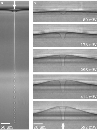
Figure 1 shows the two different types of deformation observed. When the laser shines downwards onto the interface, so that the beam travels from the phase with the higher refractive index to the phase with the lower refractive index, a long, thin jet of the upper-layer liquid forms along the beam axis and intrudes deep into the lower fluid [Fig. 1(a)] Casner and Delville (2003). Sporadically, the end of the jet sheds droplets. For modest laser powers, the shedding is regular in time and allows us to measure the volume flux, which is typically several tens of cubic microns per second. When the laser shines upwards, the interface remains unbroken even at high power. Instead, a downward tether forms on the interface due to radiation pressure effects Casner et al. (2003). Away from the centerline, the interface also deflects upwards, forming a hump whose lateral lengthscale is much larger than the beam width [Fig. 1(b)].
Previous works have analyzed how the difference between the refractive indices of the two liquid phases results in a radiation pressure which deforms the interface Casner and Delville (2001, 2003). While this mechanism explains the beam-sized deformations, it cannot explain either the jet or the broad hump. In this Letter, we show that these structures demonstrate the presence of a bulk flow driven by light scattering. The rest of this paragraph gives the key points of our argument, which are also illustrated in Fig. 2. We begin with the simpler question of how a broad hump is created when the interface is illuminated from below. Light scattering produces an upwards body force on the liquid within the laser beam, driving an upwards flow within the lit region. By conservation of fluid mass, this flow is replenished by a downwards flow. In the experiment, and in most situations of interest, inertial effects are negligible. Since purely viscous flows minimize dissipation Batchelor (1967), the replenishing flow takes the form of a single toroidal recirculation. Viscous stresses associated with the recirculation deform the interface upwards. This creates a hump whose width corresponds to the size of the recirculation and is therefore much wider than the laser beam.

In the rest of the paper, we show that the qualitative scenario described above can quantitatively account for the broad hump shapes measured. In addition, we estimate the volume flux of flow driven by the light in the jetting regime and find reasonable agreement with the measured values.
The fluid used in the experiments is a water-in-oil micellar fluid at a critical composition. Above the critical temperature , the fluid separates into two immiscible phases with different micelle volume density , in a second-order phase transition pha . Near the critical temperature, many physical properties scale like power laws in . For our purpose, the most important scaling behavior is the divergence of the osmotic compressibility, . The fluid experiences fluctuations in its order parameter, , which act as light scatterers. These fluctuations have a correlation length , which is typically hundreds of Angstroms. The very weak absorption of light at the laser frequency (cm-1) ensures that laser heating is negligible. The fluid is enclosed in a thermally controlled fused quartz cell (mm3). Optical forcing is provided by a linearly polarized TEM00 continuous Ar+ laser, with a vacuum wavelength of Å and a beam power W. The beam has a Gaussian profile with width , varying from to . More details about the experiment can be found in Casner and Delville (2001).
We can construct a simple argument for how , the strength of the light-induced flow, depends on the light intensity. The momentum per unit volume transferred from the laser beam into the liquid via scattering is proportional to the beam intensity . Therefore the body force is also proportional to . This body force acts as a pressure gradient along the beam axis. Balancing against viscous resistance , where we use the beam width as a characteristic lengthscale of the light-induced flow, yields
| (1) |
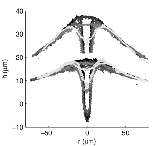
This argument predicts, counter-intuitively, that the flow strength has no dependence on the beam intensity. It only depends on the beam power. If this is true, then the interface deformation created by the flow should also have no dependence on the light intensity. Figure 3 shows two sets of measured hump profiles. Each set is taken at a fixed beam power, with the different profiles corresponding to different beam sizes. Remarkably, consistent with the prediction (1), the hump shape away from the center remains the same for different beam widths when the power is held constant. In contrast, the downward-pointing tether at the center of the hump, previously shown to be created by radiation pressure, varies with the beam width.
Next, we explicitly calculate the shape of the interface deformation as a function of and and compare the calculated shapes with the measured shapes. This requires us to first relate , which characterizes the strength of the recirculation, to the laser power , and then to relate the shape deformation to .
To obtain , we note that each scattering off a density fluctuation transfers momentum to the fluid. Summing the individual contributions from all fluctuations in a unit volume gives the body force:
| (2) |
where describes the interaction of the light with the density fluctuations and is given by . Here, and is the index of refraction. This result comes from a calculation analogous to the turbidity calculation by Puglielli and Ford Ornstein and Zernike (1914); Puglielli and Ford (1970). Since the correlation length is shorter than the wavelength of light in the regime examined, the fluctuations act as Rayleigh scatterers. The calculation also assumes single scattering, which is justified by the large turbidity length. Combining this result with the balance from (1), we see
| (3) |
where is an undetermined numerical prefactor dependant on the details of the coupling of the light-scattering force to the large-scale flows. The velocity scale is roughly tens of microns per second for experimental conditions.
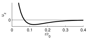
We next relate the flow within the region illuminated by the laser beam to the large-scale recirculating flow responsible for the broad hump. The liquid in the lower layer lies within a cylindrical cell of radius and depth . Since the laser beam width is much narrower than the width of the recirculation, we represent the light-induced flow as simply a point force along the centerline of a cylindrical cell. Also, as the interface deformations are much smaller than the scale of the flow, we treat the interface between the layers as perfectly flat. These simplifications allow us to obtain an analytic solution for the bulk flow. In our model, the single toroidal recirculation corresponds to an eigenfunction which satisfies no-slip boundary conditions on the side walls of the container and free-stress boundary conditions on the top and bottom surfaces of the container. The top and bottom boundary conditions are not consistent with the experimental situation. However the error introduced primarily affects the absolute scale for the strength of the recirculation, which controls the absolute scale for the height of the interface deformation. It has little effect on the relative shape of the deformation or how it changes with the laser power or the temperature , which are the aspects we focus on when we compare the calculation with the measurements. Figure 4 plots the vertical velocity in the middle of the liquid layer. Note the flow is upwards at small and downwards near the side-wall, consistent with the sketch in Fig. 2.
Finally, we relate the interface deformation to the viscous stresses associated with the toroidal recirculation, and therefore to the laser power . Because the capillary lengthscale goes to near , buoyancy is as important as surface tension in resisting the deformation. The steady-state interface is therefore given by
| (4) |
where is the mean curvature of the interface. To display the various dependencies of , we have rewritten it in terms of a dimensional stress and two dimensionless quantities, the constant and the function describing the radial decay of the stress. The boundary condition at the wall of cylindrical cell is . Near the centerline, the interface develops a downward tether due to radiation pressure. We account for this tether by imposing the boundary condition at , which mimics the observed circular rim, created by radiation effects which are not included here.
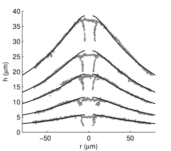
Numerical solutions of (4) at different laser powers are displayed in Fig. 5, together with experimentally measured interface profiles at the same laser powers. Values of the material parameters and beam size used in the calculation are taken from the experiment. The value of the unknown constant is fixed at by requiring that the maximum height of the calculated shape equals the measured shape at mW. This is the only fitting adjustment we have made between the calculation and the measurement. The agreement between the measured and the calculated interface shapes is excellent. Comparisons at larger for a range of powers produced good agreement as well, although the smaller size of the hump at larger makes detailed comparisons less precise. This behavior in rules out thermocapillary flows, used to drive drop motion in previous studies Garnier et al. (2003), which vanish close to the critical point.
We next consider the liquid transport inside the jet. While the complexity of the pattern of light propagation at the interface prevents a detailed comparison between the calculation and the measurements, it is possible to obtain a rough estimate. Since the jet radius is observed to increase weakly with the beam power and is always less than the beam size , we assume simply that the power of the light trapped inside the jet is , a fraction of the incident beam power. Given the beam power inside the jet and (3), the transport flux is
| (5) |
This estimate gives the right order of magnitude for the volume flux. For example, an experiment with mW at K and yields a jet with roughly m radius and measured volume flux of s. The estimate (5) gives s.
In conclusion, we have used a combination of experiment and theory to demonstrate that light-scattering can produce a significant flow in a structured fluid. In the experiment, we measure the large-scale interface deformation and the liquid transport produced by illumination of an intense laser. To show that the deformation is a result of light-induced flow, we compare interface deformations calculated based on the light-scattering mechanism against measured deformations. Excellent agreements are found between the calculated and the measured deformations. We emphasize that such light-induced flows exist whenever fluids have mesoscopic spatial variation in the refractive index and do not require the fluid to be near a second-order phase transition. For example, a suspension of nm-diameter glass beads in water at volume fraction would experience a scattering force times larger than is seen in our experiment. While such an effect has been used to transport individual colloidal particles whose size is comparable with the beam width Hart and Terray (2003), the possibility of transporting smaller colloidal particles collectively has not been noted before and is worth further investigation.
Acknowledgements.
The authors thank B. Issenmann for providing experimental data on the jet. This work was supported by a National Science Foundation Graduate Research Fellowship (RDS), NSF MRSEC DMR-0213745 (U. Chicago), and the Centre National de la Recherche Scientifique and Conseil Régional d’Aquitaine.References
- Ackerson et al. (1975) B. J. Ackerson, C. M. Sorensen, R. C. Mockler, and W. J. O’Sullivan, Phys. Rev. Lett. 34, 1371 (1975).
- Pine et al. (1988) D. J. Pine, D. A. Weitz, P. M. Chaikin, and E. Herbolzheimer, Phys. Rev. Lett. 60, 1134 (1988).
- Berne and Pecora (2000) B. J. Berne and R. Pecora, Dynamic Light Scattering (Dover Publications, 2000).
- van Megen and Underwood (1993) W. van Megen and S. M. Underwood, Phys. Rev. E 47, 248 (1993).
- Ashkin (1997) A. Ashkin, Proc. Natl. Acad. Sci. USA 94, 4853 (1997).
- Xu et al. (2004) J. Xu, J. Drelich, and E. M. Nadgorny, Langmuir 20, 1021 (2004).
- Terray et al. (2002) A. Terray, J. Oakey, and D. W. M. Marr, Science 296, 1841 (2002).
- Grier (2003) D. G. Grier, Nature 424, 810 (2003).
- Enger et al. (2004) J. Enger, M. Goksör, K. Ramser, P. Hagberg, and D. Hanstorp, Lab. Chip 4, 196 (2004).
- MacDonald et al. (2003) M. P. MacDonald, G. C. Spalding, and K. Dholakia, Nature 426, 421 (2003).
- Ozkan et al. (2003) M. Ozkan, M. Wang, C. Ozkan, R. Flynn, A. Birkbeck, and S. Esener, Biomed. Microdevices 5, 61 (2003).
- Neale et al. (2005) S. Neale, M. P. MacDonald, K. Dholakia, and T. F. Krauss, Nature Materials 4, 530 (2005).
- Casner and Delville (2003) A. Casner and J.-P. Delville, Phys. Rev. Lett. 90, 144503 (2003).
- Casner et al. (2003) A. Casner, J.-P. Delville, and I. Brevik, J. Opt. Soc. Am. B 20, 2355 (2003).
- Casner and Delville (2001) A. Casner and J.-P. Delville, Phys. Rev. Lett. 87, 054503 (2001).
- Batchelor (1967) G. K. Batchelor, An Introduction to Fluid Dynamics (Cambridge University, 1967).
- (17) Although the fluid is a quaternary mixture, the phase transition belongs to the (, ) universality class of the Ising model [E. Freysz, E. Laffon, J.-P. Delville, and A. Ducasse, Phys. Rev. E 49, 2141 (1994)].
- Puglielli and Ford (1970) V. G. Puglielli and N. C. Ford, Jr., Phys. Rev. Lett. 25, 143 (1970).
- Ornstein and Zernike (1914) L. S. Ornstein and F. Zernike, Proc. Kon. Ned. Akad. Wetensch. 17, 793 (1914).
- Garnier et al. (2003) N. Garnier, R. O. Grigoriev, and M. F. Schatz, Phys. Rev. Lett. 91, 054501 (2003).
- Hart and Terray (2003) S. J. Hart and A. V. Terray, Appl. Phys. Lett. 83, 5316 (2003).