Optical transfer cavity stabilization using current-modulated injection-locked diode lasers
Abstract
It is demonstrated that RF current modulation of a frequency stabilized injection-locked diode laser allows the stabilization of an optical cavity to adjustable lengths, by variation of the RF frequency. This transfer cavity may be used to stabilize another laser at an arbitrary wavelength, in the absence of atomic or molecular transitions suitable for stabilization. Implementation involves equipment and techniques commonly used in laser cooling and trapping laboratories, and does not require electro- or acousto-optic modulators. With this technique we stabilize a transfer cavity using a RF current-modulated diode laser which is injection locked to a reference diode laser. The reference laser is stabilized using polarization spectroscopy in a Rb cell. A Ti:sapphire ring laser at is locked to this transfer cavity and may be precisely scanned by varying the RF modulation frequency. We demonstrate the suitability of this system for the excitation of laser cooled Rb atoms to Rydberg states.
pacs:
23.23.+x, 56.65.DyI Introduction
It is often necessary to stabilize lasers at frequencies where direct locking to an atomic or molecular reference line is not possible. Several methods are commonly used for this purpose. One is to stabilize the target laser by comparison with a second laser (reference laser), which is stabilized to an absolute frequency reference such as an atomic or a molecular absorption line. If the frequency of the reference laser is sufficiently close to the frequency of the target laser, the two lasers may be heterodyned on a photodetector and the resulting beat note can be used to stabilize the target laser.1969-2 However, this is only practical up to a certain frequency difference due to the bandwidth of the photodetector.
An alternative technique is to use an optical cavity to “transfer” the stability from a stabilized reference laser to the target laser.1991 ; 1998 ; 2002 ; 1979 ; 1994 ; 1996 ; 1982 ; grabowski2005 One way this may be accomplished is by repetitively scanning the length of a “transfer cavity” (TC) with piezoelectric transducers (PZTs). The transmission fringe positions of the target laser are then compared to the reference laser using specialized digital circuitry1991 or computers.1998 ; 2002 This comparison is used to derive an error signal which may be fed back to the target laser for stabilization. Using this technique, Zhao et al. 1998 have demonstrated a long-term frequency drift on the order of . However, the scanning rate of the cavity puts a limit on the maximum rate of error correction. We have also found that this approach is sensitive to low frequency vibrations. The complexity of the fringe comparison is an additional drawback.
Scanning the cavity length may be avoided by making the transmission maxima of both the reference laser and the target laser coincide at the same cavity length.1979 ; 1994 ; 1996 ; 1982 ; grabowski2005 In this case, the cavity is locked to the reference laser and the target laser is locked to the cavity using analog circuitry. To make the fringes coincide it is possible to frequency shift either the reference or the target laser using an electro-optic modulator (EOM)1979 or an acousto-optic modulator (AOM).1996 ; grabowski2005 In this way, frequency stability and precise RF frequency tunability can be obtained. Since, in general, frequency shifts on the order of the free spectral range of the cavity may be required, the modulator in these systems should be capable of producing a broad-band of frequency shifts in order to avoid an inconveniently long transfer cavity.
In this paper, we present a technique for obtaining these frequency shifts that is inherently broadband and relatively easy to implement without using AOMs or EOMs. A Fabry–Perot TC is stabilized using a tunable sideband from a current-modulated diode laser. The carrier of this slave laser is injection locked to a second diode laser (master laser)2001 that is stabilized using an atomic reference. By adjusting the RF frequency of the current modulation of the injection locked slave laser, the TC may be tuned to the desired length for stabilization.
II Experimental Setup
The stabilization scheme has been developed for a commercial ring Ti:sapphire laser (Coherent MBR-110). This laser is frequency doubled in an external ring resonator (Coherent MBD-200) to produce approximately at , and used with lasers to excite cold Rb atoms to Rydberg states.pra2006 Since frequency stabilized lasers are required in our experiment to laser cool Rb atoms, they are convenient references for transfer cavity stabilization.
The locking procedure is as follows: The laser is tuned by hand to the desired frequency. The master (reference) laser is locked using polarization spectroscopy.pearman2002 With the TC in scanning mode, injection locked operation of the slave laser is verified. RF current modulation is then applied to the slave laser, which produces two significant sidebands at , the modulation frequency.2001 The RF modulation frequency is chosen so that a transmission peak of a sideband coincides with a transmission peak. Cavity ramping is then stopped and the cavity is locked to the sideband transmission peak and the laser is locked to its own transmission peak. The lock point of the may be varied by changing the frequency of the slave laser current modulation,
Figure 1 illustrates the experimental setup. The reference laser is an external cavity, grating stabilized, diode laser (Toptica, DL100) operating at with a maximum output power of and short term frequency stability of . The laser can be coarsely tuned by manually adjusting the grating angle, and fine-tuning is obtained using a PZT. A small fraction of the linearly polarized laser beam from this laser is diverted and divided into two beams. One is used for Rb saturation absorption spectroscopy (SAS),preston1996 which serves as a frequency identifier, and the other beam is directed to a Rb polarization spectroscopy setup for frequency locking.pearman2002 The rest of the reference laser output beam is coupled into a single mode fiber and the collimated output beam from this fiber is used to injection lock the slave laser.
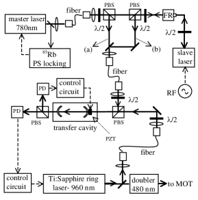
The slave laser is a commercial diode laser (Sanyo, DL7140-201S) in a temperature stabilized mount (Thorlabs, TCLDM9). Current modulation is applied using a bias-T, driven by a RF synthesizer (typically operated at 100-400 MHz, 18 dBm). The slave laser is coupled into a single mode fiber [path (b) in Fig. 1]. The output beam from the fiber is passed through a half wave plate and a polarizing beam splitter (PBS) to obtain a well-defined polarization. This beam is then fed into the TC, which may be temporarily operated as a scanning Fabry-Perot interferometer. A small fraction of the master laser beam is also fed into the TC for verifying the injection locking [path(a) in Fig. 1].
Why not simply current-modulate the reference laser directlymyatt1993 and lock the cavity to one of the resulting sidebands? Although this will work in principle, there are a number of reasons to prefer the use of a current-modulated slave laser, despite the additional complexity. If the reference laser were directly modulated, the stability of its frequency lock would be compromised, particularly if the modulation frequency were varied. In addition, by leaving the stabilized laser unmodulated, we can use part of its beam for other purposes. For example, in our experiment it is also used as a reference for beat-note locking1969-2 ; schunemann1999 the diode laser systems used for a magneto-optical trap.
The TC is of the confocal Fabry-Perot type, consisting of two mirrors with radii of curvature , separated by with a free spectral range of . It is desirable to have good finesse, thus good reflectivity at both and . It was possible to choose a standard dielectric mirror coating which exhibits high reflectivity at these two wavelengths (Newport, BD2). A PZT is mounted on one of the end mirrors. The typical finesse of the TC is and is limited by beam alignment and difficulty in obtaining the exact confocal condition.
A small fraction of the Ti:sapphire target laser beam is coupled into a single mode fiber. On emerging from the fiber, the light is passed through a PBS to ensure the beam is linearly polarized, and then aligned into the TC. After the orthogonally polarized and laser beams emerge from the TC, they are separated by a PBS and directed onto photodiodes.
The TC length is dithered slightly at using the PZT by an amplitude on the order of the cavity linewidth. Lock-in amplifiers are used to demodulate the transmission through the TC for both wavelengths.1994 ; 1982 This provides a derivative-like lineshape error signal for locking the transmission maxima. The error signal is used in an integrator feedback loop which adjusts cavity length using the PZT. This stabilizes the TC length. The error signal is fed into another integrator control loop which uses the “Ext Lock” of the target laser control box to adjust the frequency. This “Ext Lock” control has a relatively low bandwidth ( ).mbr However, this laser system is pre-stablized using a low-finesse cavity in a similar manner to the system described in Ref. 1982, .
III Result
The tuning accuracy and the drift behavior of the frequency locked target laser is characterized using Rydberg atom excitation in a 85Rb magneto-optical trap (MOT). The details of this apparatus appear elsewhere.prl2004 ; pra2006
The excitation of cold 85Rb atoms to Rydberg states occurs as a two-color process with nearly resonant light ( - and light ( - The light is necessary for the 85Rb MOT and is detuned to the red of the F=3 to F=4 transition. The light is obtained by frequency doubling the output of a Ti:sapphire ring laser – the target laser for our stabilization scheme.
The cooling and trapping light remains on continuously. The light is pulsed on for using an acousto-optic modulator. A pulsed electric field is then applied to field-ionize any Rydberg atoms and draw the resulting ions to a microchannel plate detector (MCP). A boxcar integrator is used to gate on the signal. The excitation and detection sequence repeat at
When the target laser is locked using the scheme described in the previous section, its output frequency may be scanned by varying the RF modulation frequency . Figure 2 shows the resulting spectrum in the range of the 85Rb - and - transitions. The strong field is responsible for the splitting of the lines into doublets. This is the Autler-Townes effect,autler1955 ; atomphoton similar to the results presented in Ref. teo2003, .

We expect the target laser frequency shift to be related to the slave laser modulation frequency shift by
| (1) |
where and are the air wavelengths of the reference laser and the target laser. In our case, the frequencies of the reference and target lasers are well-known, but we must estimate the corresponding refractive indices to determine the air wavelengths. Equation (1) can be tested using the observed separation of the () and () peaks in Fig. 2, together with the known - energy separation.wenhui2003 As shown in Fig. 2, the Autler-Townes splitting of and lines are identical and thus we do not expect these to contribute to the separation of the () and () peaks. We find , compared to Eq. (1), which predicts .
By repetitively scanning over the spectrum shown in Fig. 2 and recording the peak positions, we can monitor the frequency drift of the locked target laser. The positions of the () and () peaks are less dependent on the frequency fluctuations of the cooling laser than the () and () peaks. Therefore, the stronger () line is used to quantify the stability of the target laser. With the locking system activated, the control voltage applied to the Ti:sapphire laser varies as time progresses. Since the approximate relationship between a change in the control voltage and the corresponding change in the output frequency is known, we can use this to estimate the frequency drift that would have occurred if the laser were not stabilized. Figure 3 is a comparison between (a) the estimated unlocked and (b) the locked frequency drifts over . There is a dramatic reduction in the long-term frequency drift when the laser is locked.

IV Performance limitations
Since the TC is not evacuated, it is limited in performance by variations in the refractive indices of air for the target laser and the reference laser wavelengths, and respectively. The environmental influences on the locked target laser frequency can be approximated using:
| (2) |
where is the target laser frequency and represents an environmental parameter such as pressure, temperature, or humidity. The resulting sensitivities are tabulated in Table 1.
| Pressure | |
|---|---|
| Temperature | C |
| Relative Humidity | % |
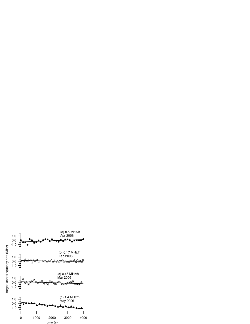
Figure 4 illustrates the frequency drift of the locked target laser as a function of time collected at various time over several months. From nine such data sets we observed an average long term () frequency drift of . This is consistent with the typical variation of environmental parameters listed in Table 1. Thus, we expect that the frequency stability of the target laser will be improved if the TC is evacuated to minimize the environmental effects.
Ultimate long-term stability is also limited by the frequency drift of the reference laser. The reference laser is frequency stabilized using polarization spectroscopy (PS) in a Rb vapor cell.pearman2002 To observe the drift of this laser we have monitored the beat note between this laser and a laser stabilized using saturated absorption spectroscopy with third-harmonic lock-in detection. The relative drift of these two systems was typically less than /hr. We have found polarization spectroscopy locking to be a good compromise between several factors, including long-term stability, robustness and complexity. However, if necessary, less long-term reference laser drift could be obtained using alternative techniques.ye1996 ; zhu1997 ; bruner1998
It is essential to be able to vary the TC length over several free spectral ranges. This is to ensure that the slave laser sideband and transmission peaks are well removed from the carrier transmission, which is stronger and may interfere with cavity locking to the sideband. This requires a long-extension PZT, which limits the bandwidth of the cavity lock and consequently the target laser lock. An improved system could use a fast short extension PZT on one end-mirror and a slower long extension PZT on the other end-mirror. The fast PZT would be used for dithering and fast cavity stabilization, whereas the slow PZT would handle long-term drift.hall2000 With these improvements it is expected that the bandwidth of the error signal would be sufficient to directly stabilize external cavity diode lasers for many applications.
V Conclusion
In this paper, we report a general technique for laser frequency stabilization at arbitrary wavelengths using a reference laser and transfer cavity. A target laser frequency drift of has been demonstrated. The equipment involved is commonly used in laser cooling and trapping laboratories, and does not require special modulators and drivers. A controllable frequency source is required, but this is the same as for electro- or acousto-optic modulators. If precise RF scanning is not required, the RF synthesizer could be replaced by inexpensive voltage controlled oscillators, as in Ref. 2001, .
VI Acknowledgements
It is a pleasure to acknowledge discussions with A. Madej (NRC, Ottawa) and J. Petrus (Waterloo). We thank M. Fedorov for fabrication and testing of the transfer cavity. This work was supported by NSERC, CFI, and OIT.
References
- (1) R. L. Barger and J. L. Hall, Phys. Rev. Lett. 22, 4 (1969).
- (2) B. G. Lindsay, K. A. Smith, and F. B. Dunning, Rev. Sci. Instrum. 62, 1656 (1991).
- (3) W. Z. Zhao, J. E. Simsarian, L. A. Orozco, and G. D. Sprouse, Rev. Sci. Instrum. 69, 3737 (1998).
- (4) A. Rossi, V. Biancalana, B. Mai, and L. Tomassetti, Rev. Sci. Instrum. 73, 2544 (2002).
- (5) B. Burghardt, W. Jitschin, and G. Meisel, App. Phys. 20, 141 (1979).
- (6) E. Riedle, S. H. Ashworth, J. T. Farrell, Jr., and D. J. Nesbitt, Rev. Sci. Instrum. 65, 42 (1994).
- (7) D. F. Plusquellic, O. Votava, and D. J. Nesbitt, Appl. Opt. 35, 1464 (1996).
- (8) J. Helmcke, S. A. Lee, and J. L. Hall, Appl. Opt. 21, 1686 (1982).
- (9) A. Grabowski, R. Heidemann, R. Löw, J. Stuhler, and T. Pfau, arXiv, quant-ph/0508082.
- (10) R. Kowalski, S. Root, S. D. Gensemer, and P. L. Gould, Rev. Sci. Instrum. 72, 2532 (2001).
- (11) K. Afrousheh, P. Bohlouli-Zanjani, J. D. Carter, A. Mugford, and J. D. D. Martin, Phys. Rev. A 73, 063403 (2006).
- (12) C. P. Pearman, C. S. Adams, S. G. Cox, P. F. Griffin, D. A. Smith, and I. G. Hughes, J. Phys. B: At. Mol. Opt. Phys. 35, 5141 (2002).
- (13) D. W. Preston, Am. J. Phys. 64, 1432 (1996).
- (14) C. J. Myatt, N. R. Newbury, and C. E. Wieman, Opt. Lett. 18, 649 (1993).
- (15) U. Schünemann, H. Engler, R. Grimm, M. Weidemüller, and M Zielonkowski, Rev. Sci. Instrum. 70, 242 (1999).
- (16) Operator’s Manual Model MBR-110 Single Frequency Ti:Sapphire Laser, Coherent (2002).
- (17) K. Afrousheh, P. Bohlouli-Zanjani, D. Vagale, A. Mugford, M. Fedorov, and J. D. D. Martin, Phys. Rev. Lett. 93, 233001 (2004).
- (18) S. H. Autler and C. H. Townes, Phys. Rev. 100, 703 (1955).
- (19) C. Cohen-Tannoudji, J. Dupont-Roc, and G. Grynberg “Atom-Photon Interactions : Basic Processes and Applications”, J. Wiley & Sons, New York, 1998.
- (20) B. K. Teo, D. Feldbaum, T. Cubel, J. R. Guest, P. R. Berman, and G. Raithel, Phys. Rev. A. 68, 053407 (2003).
- (21) W. Li, I. Mourachko, M. W. Noel, and T.F. Gallagher, Phys. Rev. A. 67, 052502 (2003).
- (22) National Institute of Standards and Technology (NIST) (http://emtoolbox.nist.gov/Wavelength/Ciddor.asp), 30 March 2006.
- (23) P. E. Ciddor, Appl. Opt. 35, 1566 (1996).
- (24) J. Ye., S. Swartz, P. Jungner, and J. L. Hall, Opt. Lett. 21, 1280 (1996).
- (25) M. Zhu and R. W. Standridge, Jr., Opt. Lett. 22, 730 (1997)
- (26) A. Bruner, V. Mahal, I. Kiryuschev, A. Arie, M. A. Arbore, and M. M. Fejer, Appl. Opt. 37, 6410 (1998).
- (27) J. L. Hall, M. S. Taubman, and J. Ye, “Laser stabilization” in Handbook of Optics IV, M. Bass, J. M. Enoch, E. Van Stryland, and W. L. Wolfe, Eds., Optical Society of America, Washington D.C., Chapter 27, McGraw-Hill, New York (2000).