Coupled applications on distributed resources
Abstract
Coupled models are set to become increasingly important in all aspects of science and engineering as tools with which to study complex systems in an integrated manner. Such coupled, hybrid simulations typically communicate data between the component models of which they are comprised relatively infrequently, and so a Grid is expected to present an ideal architecture on which to run them. In the present paper, we describe a simple, flexible and extensible architecture for a two-component hybrid molecular-continuum coupled model (hybrid MD). We discuss its deployment on distributed resources and the extensions to the RealityGrid computational-steering system to handle coupled models.
pacs:
83.10RP, 47.11.Mn, 47.11.-jI Introduction
Multi-scale modelling of physical systems is often employed to enable an accurate but computationally expensive model to be applied to the regions of a system where it is essential while a less accurate model can be used for the remainder. This enables far larger systems and longer timescales to be modelled than can be tackled using the accurate model alone.
A multi-scale model may be constructed by coupling together different simulation codes, each specializing in modelling a region of the system on one particular scale. Such a model then consists of a set of two or more codes which are synchronized through the (repeated) exchange of information as they execute. It could also be written as a single executable code but, for flexibility, scalability and ultimately, performance reasons, we consider the case of a coupled model constructed from independent components which are interfaced to allow them to exchange information. These components are then free to be deployed in such a way as to make the best use of available resources, something that is particularly important in a Grid environment.
Heart modelling provides a good example of multiscale complexity. Within the Integrative Biology (IB, http://www.integrativebiology.ac.uk) project the use of coupled models is being investigated in the area of heart disease and cancer modeling gavaghan05 ; hey05 . The IB project aims to develop an integrated approach to multiscale computational modeling of these diseases. Currently, the results of a heart cell model are integrated into an electro-mechanical finite element discretization of the heart muscular fibers (http://www.physiome.org). In the future, the molecular level description of ion channels and drugs interfering with them could be integrated within a systems biology model of the heart cell which simulates the system response to changes in parameters related to these ion channels. Although we are still far from a complete integration of this type, coupling between the heart cell model and a finite element discretization of the heart is routinely performed to study the activation potential and possible routes to the development of arrhythmias and defibrillation rodriguez05 .
The complexity of coupling multiple descriptions implies that, in the long term, coupled models may be better handled by a series of coupled codes rather than a single monolithic application which will be difficult to develop, maintain and deploy. One step in this hierarchy of scales which addresses the coupling of multiple descriptions of matter is what we call “hybrid MD”. This approach is based on a multiscale hybrid scheme, in which two or more contiguous sub-domains are dynamically coupled together, the simplest case corresponding to one sub-domain being described by molecular dynamics, the other by continuum fluid dynamics buscalioni03 ; buscalioni05 ; buscalioniPhilTrans05 ; defabritiis06 . The motivation for this hybrid approach to the description of fluids is that it enables us to tackle problems that are not addressable by any one single technique; such problems include situations in which hydrodynamic effects influence molecular interactions and vice versa at interfaces, lipid bilayer membranes and within individual macromolecules or assemblies of them. Since the computational overhead of coupling the molecular and continuum regions is very low, we can use this approach to perform coupled simulations using small molecular dynamics (MD) domains which are free of finite size effects, whilst reducing the computational cost compared with fully atomistic simulations.
Over the course of the RealityGrid project (http://www.realitygrid.org), the introduction of launching, monitoring and steering functionalities to existing scientific codes has proved successful in and out a Grid environment ReG_steering03 ; ReG_PhilTransSteering04 . The prevalent software model for grid computing is that of a service-oriented architecture (SOA). Software components in a SOA environment comprise loosely coupled interoperable application services, implemented as Web services, accessible via SOAP operations whose capabilities are described by Web service description language documents. The SOA methodology underpins the software described here. Indeed, the developments described in the present paper have evolved from the RealityGrid project. The process of “computational steering” refers to the interaction of a scientist with his/her running application. At its simplest, this may consist of monitoring the values of a few key variables to check the progress of the application and possibly altering the values of parameters of the simulation. More advanced uses may involve the scientist altering variables that control algorithms within the code and ultimately the development of complex workflows. Such use enables scientists to further develop and apply their intuition to enhance the investigation of the system under study. On-line visualization of the system is a powerful aid in this process since it can provide the user with visual feedback on the consequences of his/her steering activity. The implementation of computational steering for coupled models presents some challenges which require extension of the RealityGrid system to handle coupled codes. Although these extensions were tested on hybrid MD, they are in fact applicable to any coupled model.
The remainder of the paper is laid out as follows. In section II we discuss the hybrid MD coupled model. We describe the architecture of this system, the communication scheme used and the way in which synchronization of the components is achieved. Following this, the use of the RealityGrid framework in deploying and managing hybrid MD is described in section III. In section IV we describe the way in which we combine information from each component to produce a description of the coupled model as a whole and thus allow a steering client to treat it as a single, steerable application.
II Hybrid molecular dynamics
Hybrid molecular dynamics (hybrid MD) is a coupled model formed by two distinct descriptions of matter. At the microscopic level, the system is modelled by classical molecular dynamics, while the mesoscale is described by a finite volume discretization of the equations of fluctuating hydrodynamics defabritiis06 . These two descriptions resolve different spatial domains and interact through a ‘hybrid’ interface where the hydrodynamic variables are coarse/fine-grained and data is transferred between models (for a detailed description see defabritiis06 ).
II.1 Model structure
We have developed a hybrid MD scheme using two independent simulation codes implementing, respectively, molecular dynamics (MD) and a finite volume discretisation of the equations of fluctuating hydrodynamics (Hydro) defabritiis06 . These two models are heterogeneous from a physical point of view but are also very different programmatically because MD is a particle code, while Hydro is mesh-based. These considerations and the need to have flexible and interchangeable components for generalization to multiple components led us to create a coupled architecture with two independent programs which exchange data, rather than a single monolithic code.
This component-based approach has significant advantages. Not least of these is that each individual component can be developed, tested and used independently as a standalone code. From a performance point of view, the scheme is scalable under extension to multiple (three, four, etc) components as is required when adding extra levels of description (e.g. a quantum mechanical one) to the physical model and possibly running each component on a different computer.
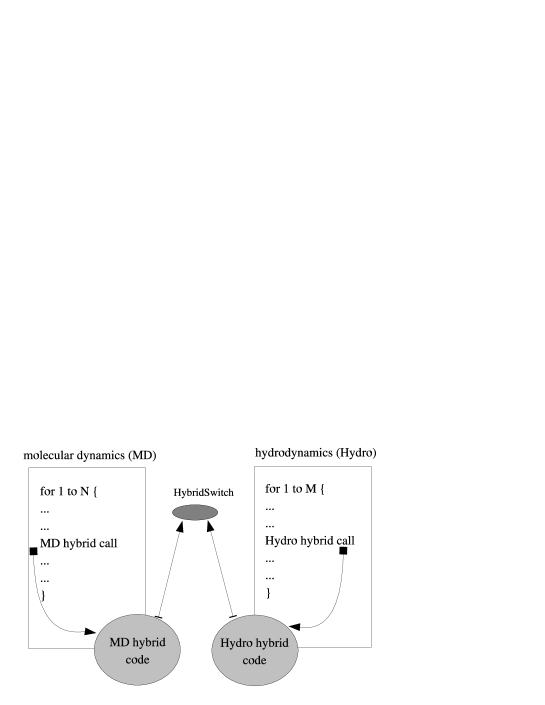
The architectural diagram illustrating how the two application components interact is shown in figure 1. The main program of each application is modified in order to accommodate a call to a subroutine from the ‘hybrid’ library which takes care of handling, preparing and communicating the data required by the hybrid coupling. This ‘hybrid’ code is rather specific and needs access to the data structures of the programs (hydrodynamics or MD). In our case we have hidden the code behind a simple interface which provides the functionality needed. As a result, the ‘hybrid’ code has to be written only once and another molecular dynamics (e.g. another serial or parallel) code could be deployed within the hybrid MD coupled model by providing the same high-level interface. Of course, building this interface requires dealing with the communication involved in gathering all the information from each processor. However, we do not expect this to affect the performance of the codes because the hybrid library is computationally light compared to the MD engine.
II.2 Component synchronisation and data exchange
A key issue for coupled models is the synchronisation of the various components. This is typically determined by the nature of the information which the components must exchange with one another and the stage during the calculation cycle at which this exchange occurs. In the models we are dealing with, each component tackles a separate physical region of the system and the data exchanged between them provides the boundary conditions for each region. The frequency of this exchange is model dependent, e.g. the timestep of a molecular dynamics simulation might be one hundredth of that of an associated continuum simulation. In this case, the two components might exchange data after every step of the continuum simulation (and thus after every 100 steps of the MD simulation). For the models we consider here, each component is arranged to be at the same point in (simulated) time whenever a data exchange takes place.
Although several specialised coupling frameworks exist, particularly in the field of atmospheric and ocean modelling CCSM3 ; CISM_coupling ; prism_coupling ; OASIS3 ; OASIS4 , we have chosen to use a very simple solution since our current models contain only two components and do not use any particular features of such frameworks. To enforce synchronisation and permit data exchange, we have constructed a communication “switch” service that implements a store and forward message-passing scheme (here called HybridSwitch). (Although this suffices for our current requirements, we mention in passing that other tools have also been considered such as the Systems Biology Workbench (SBW) SBW .) The interface to this switch service consists simply of a non-blocking put operation and a blocking get operation. It is the use of the latter that enforces inter-component synchronisation. In order to avoid deadlock in such a scheme, each component must execute its ‘puts’ and ‘gets’ in a way that is appropriate to the blocking behaviour of the communication. Essentially, this corresponds to executing the non-blocking ‘puts’ before the ‘gets’ (see gcf_coupling ).
Our experience within the RealityGrid project has consistently shown that establishing some sort of socket-based connection between applications running on different machines is plagued with problems. It is not unusual for machines that are explicitly stated to be ‘Grid-enabled’ to have no facility for direct network connections to the processors on which jobs are run (for instance, the core ‘computational’ nodes on the UK National Grid Service). In the worst case, the nodes on which a job runs might not have any internet connectivity. More common is the case where Network Address Translation or tunnelling (via a head node) is used so that ‘back-end’ nodes can connect out to the Internet but do not themselves have unique IP addresses, thus preventing incoming connections to software running on these nodes, even if local firewall rules permit. Introducing the HybridSwitch as a third party in order to mediate communication between components alleviates some of these difficulties. In particular, any connection is always initiated by a model component connecting to the HybridSwitch. Therefore, provided that any firewall around the machine running the HybridSwitch is configured to allow incoming connections and that any firewalls on the machines hosting components allow outgoing connections, the communication will at least be free of firewall-related problems.
In our implementation, components connect to and communicate with the HybridSwitch service, creating a communications network with a star topology. This topology is perfectly adequate for the loose coupling of hybrid MD. For other types of applications, multiple HybridSwitches could be deployed on different machines in order to share the network load. Each component is assigned a unique identifier (hostname:port:jobid) which is used for message routing purposes. Although indirecting messages through the HybridSwitch imposes a latency penalty, there are several compensating benefits:
-
1.
Loose coupling of components: Because messages are indirected, an individual component need not know the location of its peers.
-
2.
Transience of components: Because the HybridSwitch buffers undelivered messages, components may be disconnected and reconnected without destabilising the coupled application. It should be noted that this may impose a performance penalty on any peer components performing a blocking wait for messages from the disconnected component. When combined with performance monitoring information, the ability to seamlessly disconnect components would facilitate full performance control PerCo through migration of components across resources.
-
3.
Firewall-friendliness: This communication scheme is firewall-friendly because any connection is always initiated by the model component and made to the HybridSwitch. Provided the HybridSwitch is located on a resource with a suitable incoming-connection firewall policy, individual components located on firewalled machines may still intercommunicate.
-
4.
Diagnostics: The HybridSwitch provides a convenient, single point at which any problems with the communications may be readily investigated.
II.3 A Couette flow simulation
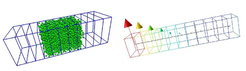
We set up a simple numerical experiment in order to deploy and test hybrid MD over distributed resources. The system comprises a three-dimensional domain of physical cells of which the in the centre are resolved with molecular dynamics (with the two external ones providing a buffer to the MD system) while the other cells are described by continuum fluctuating hydrodynamics defabritiis06 (figure 2). The continuum model is terminated by no-slip boundary conditions: the right wall does not move, while the left wall moves at velocity Å/ps. The velocity profile produces a momentum transfer across the cells which is transferred from the continuum (cells 9-15) to the MD region (cells 7-9) and again to the continuum (cells 1-6). For this simple case the analytical solution is known and, at the stationary state, is a linear decay of the velocity profile (figure 2).
III Deploying a coupled model within the RealityGrid framework
The RealityGrid framework ReG_PhilTrans_TeraGyroid can be used to deploy, steer and otherwise control the components of the hybrid MD coupled model, including any associated visualization components. Here we describe the deployment and control of hybrid MD simulating a Couette flow (see section II.3) distributed over a number of different machines. The HybridSwitch service runs on an independent machine listening on a given port.
III.1 Deployment
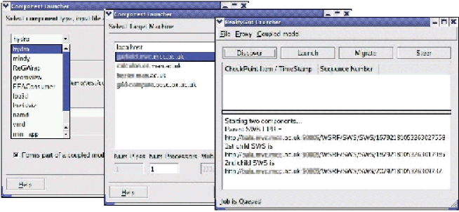
We use the RealityGrid launching client running on the user workstation to deploy each component of the model onto suitable resources. As shown in the left of figure 3, the user first selects which component of the coupled model to deploy (MD or Hydro), any associated input files and the resource on which to run it from drop-down lists (middle of figure 3). If a component is parallel then the user can also specify the number of processors to use. Because of the coupling architecture provided by the HybridSwitch, each component need only know the exact location and port of the switch. Once the input files for all of the components comprising the model have been entered, the launcher proceeds to start each of them and their associated web services (right of figure 3 and section IV). Either secure shell (ssh) or Globus globus (according to user preference and machine accessibility) is used to begin the execution of each component on the remote resource chosen for it by the user.
During the launching process, the details of each component and the coupled model as a whole are collected. This information is then published in a central registry allowing the user (or a collaborator) to subsequently examine what jobs are running and possibly attach a steering client to them.
The launching client is also employed when the user wishes to deploy an on-line visualization in order to monitor the state of a particular component in more detail. In this case, the launcher interrogates the registry and provides a list of the components that are currently running. The user selects the one to be used as a data source for the new visualization and then proceeds as for a simulation component. The creation of the (socket) connection between the visualization and simulation components is mediated by the underlying web services.
III.2 Performance Control
Once a coupled model has been made steerable, it becomes possible to implement more advanced functionality. We have previously created a framework for job migration for single-component models using the steering functionality and its support for check-pointing ReG_PhilTrans_TeraGyroid . Job migration underpins the ability to dynamically manage the performance of a running application (e.g. by migrating the job to either a less heavily-loaded machine or to a faster machine that was not available when the job was initially launched), whether manually or automatically.
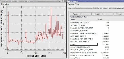
With the move to distributed, multi-component models, the need for performance control becomes more pressing and the task more complex. In general, each component of a coupled model will have different performance characteristics and therefore the resources that must be allocated to each to maximise the performance of the model as a whole are not straightforward to determine. Optimising the performance of such a model therefore requires the determination of the rate-limiting component and the subsequent migration of it to a more powerful/suitable resource, if available. In the case of hybrid MD, the perfomance on the specific machine can be determined on-the-fly by the RealityGrid monitoring capabilities. In figure 4, the elapsed time per iteration of the Hydro component is monitored while an artificial load is applied to the machine. The user may then decide to checkpoint the codes using the RealityGrid checkpoint command and then restart it somewhere else. This provides a very first simple and manual performance control over the coupled model as a whole. In principle, the RealityGrid system and the HybridSwitch also permit individual components to be stopped and restarted without the loss of synchronization. However, hybrid MD does not support this feature as yet.
Our existing job migration system is based upon the ability to instruct a job to create a checkpoint and then record the details of that checkpoint (location and names of files, snapshot of model parameters etc.) with a web service ReG_PhilTrans_TeraGyroid . For a coupled model a job comprises two coupled applications, therefore the instruction to create a checkpoint must be carried out by all components at the equivalent point in simulated time. The metadata for each component’s checkpoint must then be gathered together and registered with the web service, as before. Using this information it is then possible to restart the coupled model as a whole on any set of available resources after having first copied the necessary sets of files to each machine. We are currently working to implement this functionality and hope to extend it so that migration of individual components may be achieved without stopping and restarting the other components of the model.
IV Representing multiple components as a single application
The RealityGrid project has developed a computational steering API and associated library ReG_PhilTransSteering04 ; sve_site , designed to facilitate the instrumentation of an application code for steering. Given that a large number of applications within the project and an increasing number from outside it are instrumented with this library, we aimed to design a system for steering coupled models that would require no API changes.
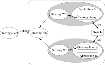
Since a coupled model ultimately represents a single physical system, it is more intuitive and thus highly desirable for a user wishing to steer it to be able to treat it as such, rather than having to consider its constituent components. In addition, this approach has the advantage that existing steering clients, originally designed to connect to one or more independent components, can be used unchanged to steer a coupled model consisting of a number of components. In light of these requirements, the architecture of our system for steering coupled models is of the form shown in figure 5. As in the standard RealityGrid steering system ReG_PhilTransSteering04 , each individual component is represented by a Steering Web Service (SWS) — a Web-Service Resource having both state and lifetime. The Web Services Resource Framework (WSRF) WSRF provides standard interfaces for managing these properties and we have implemented the SWS using the WSRF::Lite Perl package WSRF-Lite . In order for the coupled model to present a single interface to a steering client, we introduce a third SWS as shown in the figure. This SWS has responsibility for taking the information available to it from its children (the SWSs representing each component) and presenting it to the client in a suitable form. Thus, the vast majority of the extensions to the RealityGrid steering system to cope with coupled models are restricted to the SWS.
Figure 5 shows a coupled model (e.g. hybrid MD) with only two components, although our approach generalises to more complex configurations, possibly requiring a deeper tree of SWSs or SWSs with more than two children (both of which are supported). In order for a coupled model consisting of two or more components to present a single steering interface, the various aspects of each component must be combined in some way. In our architecture, this is performed by any SWS that has SWSs as its children. Thus, in figure 5, the left-most SWS is responsible for making available the results of combining the information from the two SWSs which communicate directly with the two components making up the application.
Within the RealityGrid steering system, each steerable component is characterised by certain metadata that is created by the steering library at runtime using the information supplied by the application. This metadata consists of:
-
1.
Steering commands (the set of steering commands supported by the component like start, pause, stop, checkpoint, etc): Since steering commands are generic to a steerable application, in order for a parent to support a command, it is necessary and sufficient that all of its children support it. Thus, the set of steering commands supported by a parent may be generated by ANDing the sets of commands supported by each of its children.
-
2.
Monitored parameters (those parameters of the component that a steering client can observe but not modify): The monitored parameters of a component are specific to it since they are a part of the state of that component. Although these parameters may represent the same physical quantity, they provide useful information on the behaviour of the two separate components and the correctness or otherwise of the coupling between them. Consequently, the childrens’ sets of monitored parameters are simply combined to form the set of monitored parameters of the parent (albeit with tags added to their labels to ensure they remain distinct).
-
3.
IO channels and checkpoint types (IO channels support general data IO whereas checkpoint types are specifically designed to support control of check-pointing and restarting a component): As with monitored parameters, the IO channels associated with each component remain distinct. These may be used to connect suitable visualization packages to one or more of the components within the application and thus need to retain their identity. In contrast, check-pointing is a more complex issue. Provided that all of the components forming the coupled model have registered at least one checkpoint type then, in principle, it is possible to checkpoint the whole application. However, for hybrid MD, it is important that each of the components create their respective checkpoints at an equivalent point in simulated time.
-
4.
Steerable parameters (those parameters of the component whose values can be altered by a steering client): Steerable parameters are the most challenging part of a component’s metadata to combine. This is because steerable parameters belonging to different children may need to be represented by a single steerable parameter in the parent.
The case of checkpoints and steerable parameters is better understood with a specific example from hybrid MD. For instance, MD and Hydro have a monitored parameter representing the current local temperature which fluctuates around a mean value given by the imposed thermostat temperature. Each component has a steerable parameter controlling the target temperature which must be the same for both components. (These component-specific parameters may well have different names, e.g. T_target and desiredTemp.)
    <SWS:Coupling_config>
      <Global_param_list>
        <Global_param name="targetTemp">
          <Child_param id="http://machine.address:10000/SWS/service/8312105489098098"
                       label="8312105489098098/T_target"/>
          <Child_param id="http://machine.address:10000/SWS/service/8312105489023033"
                       label="8312105489023033/desiredTemp"/>
        </Global_param>
      </Global_param_list>
    </SWS:Coupling_config>
The RealityGrid steering system handles this case by defining such parameters as being global within the scope of the parent. Any change that a user makes to such a parameter must be passed down to the components in such a way that the change occurs in synchronized fashion, i.e. at equivalent points in simulated time. It is up to the developer of the coupled model to decide which parameters belong to a single description and which are intrinsically coupled.
A fragment of metadata to describe such global parameters is shown in figure 6 where a new, global parameter targetTemp is defined as being equivalent to one child’s T_target parameter and the other child’s desiredTemp parameter. This metadata is supplied to the parent SWS which then uses it to perform the necessary processing of its childrens’ parameters. (Since all messaging and metadata within the RealityGrid system uses XML, it is well suited to processing in this way.) Once a parent SWS has used the supplied metadata to process its children’s steered parameters, the set of steered parameters that it will supply to any attached steering client will contain the targetTemp parameter in place of both T_target and desiredTemp. Thus the steering client will have a single steerable parameter to control the target temperature in both of the components. Currently, our system assumes that the parameters making up a global parameter are all in the same units although any necessary scaling factors could, in principle, be included in the metadata.
When the user steers a global steered parameter, it is the parent SWS’s responsibility to ensure that the change to each of the constituent parameters occurs at the same point in simulated time in each component. In order to achieve this, the parent SWS must have knowledge of the current simulated time of each of its child components. This is achieved by requiring each component of a coupled model to register a special steered parameter controlling the value of the time step. Given that the steering library can monitor the number of timesteps completed, it can then also calculate the total amount of time that has been simulated and make this available (as a monitored parameter). Given knowledge of each child component’s time-step and current simulated time, the parent SWS can calculate a suitable future simulated time, , at which to make the change to the constituents of the global parameter. It then inserts this information into the control message (describing the change in parameter value) being sent to each child. The steering library has been extended to make use of this information — a message tagged in this way is stored and only acted upon once the specified time has been exceeded by the component.
The same approach is used when check-pointing. A is generated and included with the command to checkpoint which is sent to each component. It is worth noting that this extension to the steering library provides most of the functionality that is necessary to enable a user to specify when certain steering actions are to be applied to a component. For instance, they may instruct a component to create a checkpoint and then stop once it has reached a certain point in simulated time. This naturally leads on to the possibility of scripted steering and the ability to “replay” a previous, steered simulation. We hope to investigate these possibilities in future work.
V Summary
In this paper we have described a possible approach to the deployment of coupled models on a general purpose Grid. The coupled model hybrid MD formed by molecular dynamics and fluctuating hydrodynamics packages was illustrated for the case of a Couette flow simulation. The two independent simulation codes communicate via a HybridSwitch service and are launched via the RealityGrid launcher application on different machines. Computational steering and online visualization were also described. The problem of performance control is particularly interesting for coupled models; we can provide this initially via manual migration of both components between computational resources on a Grid. In the future, automated performance control may be included in the RealityGrid framework. The generalization of the coupling protocol described here to the case of multiple components will also be explored.
Acknowledgements.
This research was supported by the EPSRC RealityGrid project GR/R67699 and the EPSRC Integrative Biology project GR/S72023.References
- [1] D. J. Gavaghan, A. C. Simpson, S. Lloyd, D. F. Mac Randal, and D. R. Boyd. Phil. Trans. Royal Soc A, 15:1829, 2005.
- [2] T. Hey and Trefethen. Science, 308:817, 2005.
- [3] B. Rodriguez, L. Li, J. C. Eason, I. R. Efimov, and N.A. Trayanova. Circ. Res., 22, 2005.
- [4] R. Delgado-Buscalioni and P. V. Coveney. Continuum-particle hybrid coupling for mass, momentum, and energy transfers in unsteady fluid flow. Phys. Rev., 67:046704, 2003.
- [5] R. Delgado-Buscalioni, E. G. Flekkøy, and P. V. Coveney. Fluctuations and continuity in particle-continuum hybrid simulations of unsteady flows based on flux-exchange. Europhys. Lett., 69:959, 2005.
- [6] R. Delgado-Buscalioni, P. V. Coveney, G. D. Riley, and R. W. Ford. Hybrid molecular-continuum fluid models: implementation within a general coupling framework. Phil. Trans. R. Soc. Lond., A363, 2005.
- [7] G. De Fabritiis, M. Serrano, R. Delgado-Buscalioni, and P. V. Coveney. Multiscale modelling of liquids with molecular specificy. 2006. preprint.
- [8] S. M. Pickles, R. Haines, R. L. Pinning, and A. R. Porter. A practical toolkit for computational steering. Philosophical Transactions of the Royal Society, A363:1843–1853, 2005.
- [9] J. Chin, J. Harting, S. Jha, P. V. Coveney, A. R. Porter, and S. M. Pickles. Steering in computational science: mesoscale modelling and simulation. Contemporary Physics, 44(2):18, 2003.
- [10] W. D. Collins, C. M. Bitz, M. L. Blackmon, G. B. Bonan, C. S. Bretherton, J. A. Carton, P. Chang, S. C. Doney, J. J. Hack, T. B. Henderson, J. T. Kiehl, W. G. Large, D. S. McKenna, B. D. Santer, and R. D. Smith. The Community Climate System Model: CCSM3. Journal of Climate, 11(6), 1998.
- [11] C. Goodrich, J. Lyon, and T. Guild. Coupling solar and terrestrial models using overture and intercomm. In Proceedings of ISSS-7, 26–31 March, 2005, 2005.
- [12] Program for Integrated Earth System Modeling. http://prism.enes.org/.
- [13] S. Valcke, A. Caubel, R. Vogelsang, and D. Declat. OASIS3 User’s Guide, 2004. PRISM Report Series No. 2 (5th Ed.), CERFACS, Toulouse, France.
- [14] S. Valcke, R. Redler, R. Vogelsang, D. Declat, H. Ritzdorf, and T. Schoenemeyer. OASIS4 User’s Guide, 2004. PRISM Report Series No. 3.
- [15] Systems biology workbench (sbw).
- [16] R. W. Ford, G. D. Riley, M. K. Bane, C. W. Armstrong, and T. L. Freeman. GCF: A general coupling framework. Concurrency and Computation: Practice and Experience (Jonh Wiley), 18:163, 2006.
- [17] K. Mayes, G. Riley, R. W. Ford, M. Lujan, and T. L. Freeman. The design of a performance steering system for component-based grid applications. In V. Getov, M. Gerndt, A. Hoisie, A. Maloney, and B. Miller, editors, Performance Analysis and Grid Computing, pages 111–127. Kluwer Academic Publishers, 2003.
- [18] R. Haines, M. Mc Keown, S. M. Pickles, R. L. Pinning, A. R. Porter, and M. Riding. The service architecture of the teragyroid experiment. Philosophical Transactions of the Royal Society, 363:1743–1755, 2005.
- [19] I. Foster and C. Kesselman. Globus: A toolkit-based grid architecture. In I. Foster and C. Kesselman, editors, The Grid: Blueprint for a New Computing Infrastructure, page 259. Morgan Kaufmann, 1999.
- [20] The steering library and documentation are available from: http://www.sve.man.ac.uk/Research/AtoZ/RealityGrid.
- [21] I. Foster, J. Frey, S. Graham, S. Tuecke, K. Czajkowski, D. Ferguson, F. Leymann, M. Nally, T. Storey, W. Vambenepe, and S. Weerawarana. Modeling Stateful Resources with Web Services v1.0, 2004. http://www-106.ibm.com/developerworks/library/ws-resource/ws-modelingresources.pdf.
- [22] M. Mc Keown. WSRF::Lite. A Perl implementation of a WSRF-compliant hosting environment. http://www.sve.man.ac.uk/Research/AtoZ/ILCT.
- [23] W. Humphrey, A. Dalke, and K. Schulten. VMD – Visual Molecular Dynamics. Journal of Molecular Graphics, 14:33–38, 1996.
- [24] R. Haines. RealityGrid AVS/Express Modules. Modules for interfacing AVS/Express to the RealityGrid computational framework. http://www.sve.man.ac.uk/Research/AtoZ/RealityGrid/avs/regsteermod.