A polarized beam splitter using an anisotropic medium slab
Abstract
The propagation of electromagnetic waves in the anisotropic medium with a single-sheeted hyperboloid dispersion relation is investigated. It is found that in such an anisotropic medium E- and H-polarized waves have the same dispersion relation, while E- and H-polarized waves exhibit opposite amphoteric refraction characteristics. E- (or H-) polarized waves are positively refracted whereas H- (or E-) polarized waves are negatively refracted at the interface associated with the anisotropic medium. By suitably using the properties of anomalous refraction in the anisotropic medium it is possible to realize a very simple and very efficient beam splitter to route the light. It is shown that the splitting angle and the splitting distance between E- and H- polarized beam is the function of anisotropic parameters, incident angle and slab thickness.
pacs:
78.20.Ci; 41.20.Jb; 42.25.GyI Introduction
Polarization beam splitter is an important device in optical systems, such as polarization-independent optical isolators and optical switches Born1999 ; Yariv1984 . A conventional polarization beam splitter is made of a nonmagnetic anisotropic crystal or a multi-layer transparent material Shiraishi1991 ; Muro1998 ; Shiraishi1998 . The separation between E- and H- polarized beams produced by these conventional methods is typically limited by the small splitting angle. While a large beam splitting angle and splitting distance are preferable for practical applications, especially in the field of optical communication systems.
In general, E- and H- polarized waves propagate in different directions in an anisotropic medium. For a regular anisotropic medium, all tensor elements of permittivity and permeability should be positive. The recent advent of a new class of material with negative permittivity and permeability has attained considerable attention Veselago1968 ; Smith2000 ; Shelby2001 ; Parazzoli2003 ; Houck2003 . Recently, Lindell et al. Lindell2001 have shown that anomalous negative refraction can occur at an interface associated with an anisotropic media, which does not necessarily require that all tensor elements of and have negative values. The studies of such anisotropic media have recently received much interest and attention Hu2002 ; Zhou2003 ; Smith2003 ; Thomas2005 ; Luo2005 ; Shen2005 ; Luo2006a ; Depine2006a ; Depine2006b . Although E- and H-polarized waves can present the amphoteric refraction in conventional nonmagnetic anisotropic crystal Luo2005 , the splitting angle is very small. A question naturally arise: whether there exists a large splitting angle and splitting distance, when E- and H-polarized waves propagating in certain anisotropic media.
In this paper we investigate the propagation of electromagnetic waves in an anisotropic material with a single-sheeted hyperboloid dispersion relation. We show that E- (or H-) polarized beam is positively refracted whereas H- (or E-) polarized beam is negatively refracted at the interface associated with the anisotropic media. There exists both a large splitting angle and splitting distance, when E- and H-polarized waves in the special anisotropic media. We present a design of polarization beam splitters based on the anomalous refraction in the anisotropic medium. To match the boundary conditions, the material parameters of the anisotropic medium can be designed.
II Dispersion relations of an anisotropic media
Before we consider the beam splitter structure, we first analyze the dispersion relation of the anisotropic medium. For anisotropic materials one or both of the permittivity and permeability are second-rank tensors Chen1983 ; Kong1990 . To simplify the proceeding analysis, we assume the permittivity and permeability tensors are simultaneously diagonalizable:
| (7) |
where and are the permittivity and permeability constants in the principal coordinate system ().
We choose the axis to be normal to the interface, and the , axes locate at the plane of the interface. We assume plane wave with frequency incident from isotropic media into anisotropic media. In isotropic media the accompanying dispersion relation has the familiar form
| (8) |
Here is the component of the propagating wave vector and is the speed of light in vacuum. and are the permittivity and permeability, respectively.
In the uniaxially anisotropic media, the E- and H- polarized incident waves have the dispersion relation Chen1983 ; Shen2005
| (9) |
| (10) |
Here represents the component of transmitted wave-vector. If the permittivity and permeability constants satisfy the relation:
| (11) |
where is a constant, then the E- and H- polarized waves have the same dispersion relation Shen2005 ; Luo2006b
| (12) |
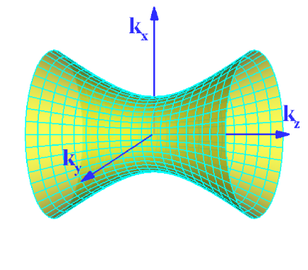
Based on the dispersion relation one can find that the wave-vector surface is a single-sheeted hyperboloid. It should be mentioned that the propagation character in quasiisotropic media has been discussed in our previous work. We have shown that E- and H- polarized waves have the same propagation character in quasiisotropic medium Luo2006a . In present work, we want to enquire whether E- and H- polarized waves have the same propagation feature.
III Positive and negative refraction
In this section, we shall answer the question asked in the above section. The -component of the wave vector can be found by the solution of Eq. (12), which yields
| (13) |
where or . The choice of the sign ensures that light power propagates away from the surface to the direction.
Without loss of generality, we assume the wave vector locate in the plane (). The incident angle of light is given by
| (14) |
In principle the occurrence of refraction requires that the component of the wave vector of the refracted waves must be real. Then the incident angle must satisfy the following inequality:
| (15) |
Based on the boundary condition, the tangential components of the wave vectors must be continuous
| (16) |
Substituting Eq. (16) into Eq. (15), one can obtain E- and H- polarized waves have the same critical angle
| (17) |
The refractive angle of the transmitted wave vector or phase of E- and H-polarized waves can be written as
| (18) |
It should be noted that the actual direction of light is defined by the time-averaged Poynting vector . For E- polarized incident waves, the Poynting vector is given by
| (19) |
For H-polarized incident waves, the transmitted Poynting vector is given by
| (20) |
The refractive angle of Poynting vector of E- and H- polarized incident waves can be obtained as
| (21) |
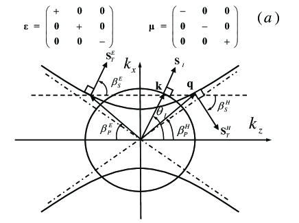
For the purpose of illustration, the frequency contour will be used to determine the refracted waves as shown in Fig. 2. From the boundary condition , we can obtain two possibilities for the refracted wave vector. Energy conservation requires that the component of poynting vector must propagates away from the interface, for instance, and . Then the sign of and can be determined easily. The corresponding Poynting vector should be drawn perpendicularly to the dispersion contour. Thus we can obtain two possibilities (inward or outward), while only the Poynting vector with is causal.
As can be seen from Fig. 2, the wave-vector surface is a
single-sheeted hyperbola. This medium
has two types:
(I) For the case of , and
, the refraction diagram is plotted in
Fig. 2a. For E-polarized incident waves , .
For H-polarized incident waves ,
. From Eqs. (19) and
(20), if ,
and have the same sign, while
and are always in the opposite sign,
i.e.
| (22) |
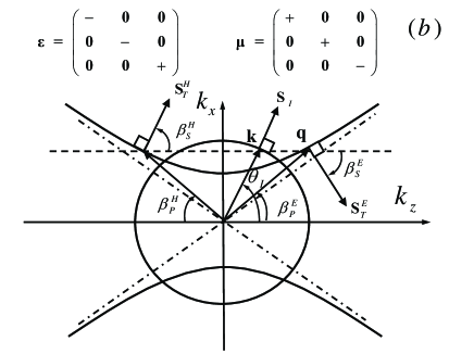
(II) For the case of , and , the refraction diagram is plotted in Fig. 2b. For E-polarized incident waves , . For H-polarized incident waves , . From Eqs. (19) and (20) we can get
| (23) |
We thus conclude that E- and H-polarized waves have the same dispersion relation while E- (or H-) polarized beam is positively refracted whereas H- (or E-) polarized beam is negatively refracted in such anisotropic media.
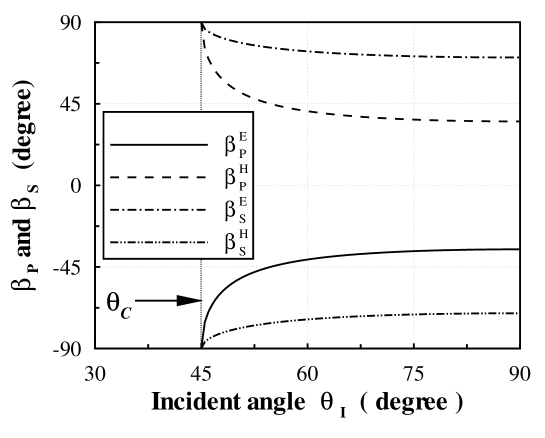
In following analysis we are interested in type I, in which the E-polarized waves are positively refracted whereas the H-polarized waves are negatively refracted. The refractive angles of Poynting vector and wave vector are plotted in Fig. 3. For the purpose of illustration, We choose some simple anisotropic parameters, i.e. , , and . It should be mentioned that the parameters can be effectively modelled in periodic wires and rings structure Smith2003 ; Thomas2005 .
The above analysis suggest that a large splitting angle can be obtained by tuning the anisotropic parameters. The splitting angle between E- and H-polarized waves can be defined as
| (24) |
If the waves incident at , the splitting angle will reach a large value as shown in Fig 3. A question naturally arise: why do we not use the special medium to construct an efficient splitter?
IV Waves incident at Brewster angle
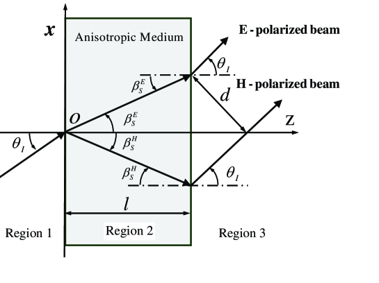
From the analysis of the previous section we know that E-polarized beam is positively refracted whereas H-polarized beam is negatively refracted by the anisotropic slab. The interesting properties allow us to introduce the potential device acting as a polarizing beam splitter. The optical beam splitter consists of an anisotropic medium slab as shown in Fig. 4.
The media parameters of anisotropic slab can be tuned to meet the requirements, for example, the reflection coefficient of a E-polarized wave equals to that of a H-polarized wave. Based on the boundary conditions, the reflection and the transmission coefficients can be obtained Luo2006b . For E-polarized incident waves, one can obtain the following expression for the reflection and transmission coefficients
| (25) |
For H-polarized incident waves, the reflection and transmission coefficients can be obtained similarly as
| (26) |
Mathematically the Brewster angles can be obtained from and . For E-polarized incident waves if the anisotropic parameters satisfy the relation
| (27) |
the Brewster angle can be expressed as
| (28) |
For H-polarized waves if the anisotropic parameters satisfy by the relation
| (29) |
the Brewster angle can be written in the form
| (30) |
It should be mentioned that E- and H-polarized waves may exhibit a Brewster angle simultaneously, which depends on the choice of the anisotropic parameters. Clearly, if one seeks a solution satisfying Eq. (28) and Eq. (30), the only possibility is
| (31) |
one can obtain an interesting features: E- and H-polarized waves will exhibit the same reflection and transmission, namely, and .
The reflection coefficients of E- and H-polarized waves are plotted in Fig. 5. We choose some simple parameters for the purpose of illustration, i.e., . In Fig. 5a E- and H-polarized incident waves exhibit a Brewster angle, simultaneously. When the incident angle equal to the Brewster angle, the incident waves will exhibit oblique total transmission. In Fig. 5b E- and H-polarized waves exhibit the same Brewster angle. We can find E- and H-polarized waves will exhibit oblique total transmission at same indigent angle.
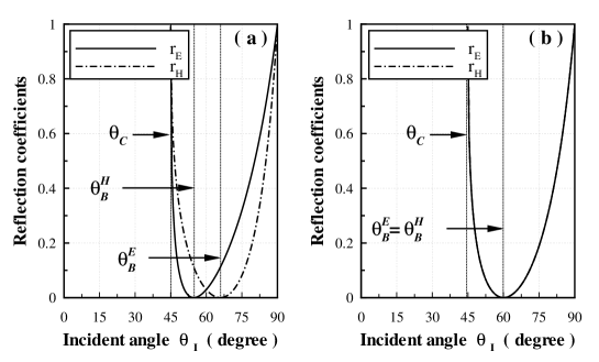
To construct an efficient splitter, we wish that E- and H-polarized waves can totally transmit thought the anisotropic slab. We thus choose the incident angle equal to the Brewster angle ==, the reflects of E- and H- polarized waves are completely absent.
V Polarizing Beam Splitter based on the anomalous refraction
The splitting distance (or walk-off distance) between E- and H- polarized beam is the functions of anisotropic parameters, the incident angle and the slab thickness. The splitting distance can be easily obtained as
| (32) |
where is the splitting distance and is the thickness of slab.
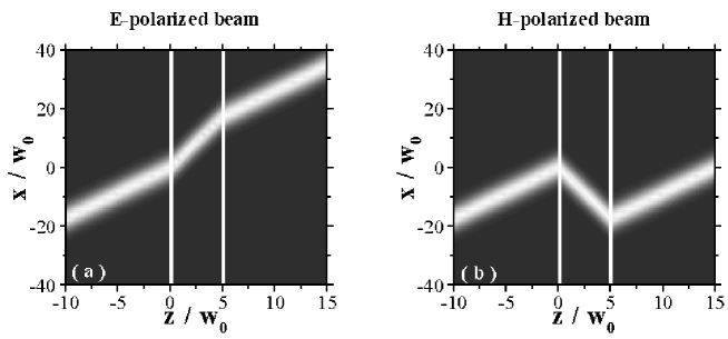
To obtain a better physical picture of beam splitter, a modulated Gaussian beam of finite width can be constructed. Following the method outlined by Lu et al. Lu2004 , let us consider a modulated beam incident from free space
| (33) |
where is perpendicular to and . A general incident wave vector is written as . we assume its Gaussian weight is
| (34) |
where is the spatial extent of the incident beam. We want the modulated Gaussian beam to be aligned with the incident direction defined by the vector , which makes the incident angle equal to the Brewster angle.
Matching the boundary conditions for each component at gives the complex field in the form
| (35) |
where is the transmission coefficient of the modulated Gaussian beam at the first interface. The transmission coefficient can obtain a good approximation to simply evaluate this quantity at . We set the waves are incident at the Brewster angle, then the transmission coefficient of the modulated beam is simply given by . The normal component of refracted wave vector can be expanded in a Taylor series to first order in to obtain a better approximation
| (36) |
| (37) |
The complex field in region can be obtained simlarlly
| (38) |
where is the transmission coefficient of the modulated Gaussian beam at the second interface. E- and H-polarized waves can totally propagate thought the interface.
To this end, the intensity distribution of the transmission field in the free space and anisotropic media slab can be derived from Eqs. (33), (35) and (38) under the above approximation. For simplicity, the isotropic medium is assumed to be a vacuum in our calculation. Note that the refraction angles of energy of E- and H-polarized beams in the anisotropic medium slab are almost exactly the analytical expression in Eq. (24). Our numerical results indicate that it is advantageous to employ the anisotropic media slab as polarization beam splitter.
Finally we want to enquire: how can the beam splitting effect be studied experimentally? Generally speaking, it is not strange to mention the question because no scheme can be of much interest if the means of realizing it are not available. Fortunately several recent developments make the beam splitter a practical possibility. An extremely promising material has been previously explored in certain designs of photonic crystals, which can be effectively modelled with anisotropic permittivity and permeability tensors Shvets2003 ; Shvets2004 ; Urzhumov2005 . Therefore there is no physical and technical obstacle to construct the anisotropic medium slab to split polarized beams.
VI Conclusion
In conclusion, we have investigated the wave propagation in the anisotropic media with single-sheeted hyperboloid dispersion relation. In such anisotropic media E- and H-polarized waves have the same dispersion relation while E- (or H-) polarized beam is positively refracted whereas H- (or E-) polarized beam is negatively refracted. By suitably using propagation properties in such kind of anisotropic medium, it is possible to realize very simple and very efficient beam splitter. We show that the splitting distance between E- and H-polarized beam is the functions of anisotropic parameters, the incident angle and the slab thickness. We are sure that our scheme has not exhausted the interesting possibilities. In particular, it might be imagined that a series of beam splitter could be constructed in more sophisticated processes than those considered here.
Acknowledgements.
This work is supported by projects of the National Natural Science Foundation of China (No. 10125521 and No. 10535010).References
- (1) M. Born, E. Wolf, Principles of Optics (Cambridge, New York, 1999).
- (2) A. Yariv and P. Yeh, Optical Waves in Crystals (John Wiley and Sons, New York, 1984).
- (3) K. Shiraishi, T. Sato and S. Kawakami, “Experimental verification of a form-birefringent polarization splitter,” Appl. Phys. Lett. 58, 211-213 (1991) .
- (4) K. Muro and K. Shiraishi, “Poly-Si/SiO2 Laminated Walk-Off Polarizer Having a Beam-Splitting Angle of More Than 20∘,” J. Lightwave Technol. 16, 127-133 (1998).
- (5) K. Shiraishi and T. Aoyagi, “Fabrication of spatial walk-off polarizing film exhibiting a large split angle by oblique silicon deposition,” Opt. Lett. 23, 1232-1234 (1998).
- (6) V. G. Veselago, “The electrodynamics of substances with simultaneously negative values of and ” Sov. Phys. Usp. 10, 509-514 (1968).
- (7) D. R. Smith, W. J. Padilla, D. C. Vier, S. C. Nemat-Nasser and S. Schultz, “Composite Medium with Simultaneously Negative Permeability and Permittivity” Phys. Rev. Lett. 84, 4184-4187 (2000) .
- (8) R. A. Shelby, D. R. Smith and S. Schultz, “Experimental VeriTcation of a Negative Index of Refraction,” Science 292, 77-79 (2001).
- (9) C. G. Parazzoli, R. B. Greegor, K. Li, B. E. C. Koltenba and M. Tanielian, “Experimental Verification and Simulation of Negative Index of Refraction Using Snell’s Law,” Phys. Rev. Lett. 90, 1074011-1074014 (2003).
- (10) A. A. Houck, J. B. Brock and I. L. Chuang, “Experimental Observations of a Left-Handed Material That Obeys Snell’s Law,” Phys. Rev. Lett. 90, 1374011-1374014 (2003).
- (11) I. V. Lindell, S. A. Tretyakov, K. I. Nikoskinen and S. Ilvonen, “BW media-media with negative parameters, capable of supporting backward waves,” Microw. Opt. Technol. Lett. 31, 129-133 (2001).
- (12) L. B. Hu and S. T. Chui, “Characteristics of electromagnetic wave propagation in uniaxially anisotropic left-handed materials,” Phys. Rev. B66, 0851081-0851087 (2002).
- (13) L. Zhou, C. T. Chan and P. Sheng, “Anisotropy and oblique total transmission at a planar negative-index interface,” Phys. Rev. B68, 1154241-1154245 (2003).
- (14) D. R. Smith and D. Schurig, “Electromagnetic wave propagation in media with indefinite permittivity and permeability tensors,” Phys. Rev. Lett. 90, 0774051-0774054 (2003).
- (15) Z. M. Thomas, T. M. Grzegorczyk, B. I. Wu, X. Chen and J. A. Kong, “Design and measurement of a four-port device using metamaterials,” Opt. Express 13, 4737-4744 (2005).
- (16) H. Luo, W. Hu, X. Yi, H. Liu and J. Zhu, “Amphoteric refraction at the interface between isotropic and anisotropic media,” Opt. Commun. 254, 353-360 (2005).
- (17) H. Luo, W. Shu, F. Li and Z. Ren, “Superluminal group velocity in an anisotropic metamaterial,” Eourphysics Letters (to be published).
- (18) N. H. Shen, Q. Wang, J. Chen, Y. X. Fan, J. Ding, H. T. Wang, Y. Tian and N. B. Ming, “Optically uniaxial left-handed materials,” Phys. Rev. B72, 1531041-1531044 (2005).
- (19) R. A. Depine, M. E. Inchaussandague and A. Lakhtakia, “Classification of dispersion equations for homogeneous, dielectric-magnetic, uniaxial materials,” J. Opt. Soc. Am. A23, 949 (2006).
- (20) R. A. Depine, M. E. Inchaussandague and A. Lakhtakia,“Vector theory of diffraction by gratings made of a uniaxial dielectric-magnetic material exhibiting negative refraction,” J. Opt. Soc. Am. B23, 514 (2006).
- (21) H. Luo, W. Shu, F. Li and Z. Ren, “Anomalous waves propagation in quasiisotropic media” (In review).
- (22) H. C. Chen, Theory of Electromagnetic Waves (McGraw-Hill, New York, 1983).
- (23) J. A. Kong, Electromagnetic Wave Theory (Wiley, New York, 1990).
- (24) W. T. Lu, J. B. Sokoloff and S. Sridhar, “Refraction of electromagnetic energy for wave packets incident on a negative-index medium is always negative,” Phys. Rev. E69, 0266041-0266045 (2004).
- (25) G. Shvets, “Photonic approach to making a material with a negative index of refraction,” Phys. Rev. B67, 0351091-0351098 (2003).
- (26) G. Shvets and Y. A. Urzhumov, “Engineering the electromagnetic properties of periodic nanostructures using electrostatic resonances,” Phys. Rev. Lett. 93, 2439021-2439024 (2004).
- (27) Y. A. Urzhumov and G. Shvets, “Extreme anisotropy of wave propagation in two-dimensional photonic crystals,” Phys. Rev. E72, 0266081-0266085 (2005).