Two-Color Fabry-Pérot Laser Diode with THz Primary Mode Spacing
Abstract
A class of multiwavelength Fabry-Pérot lasers is introduced where the spectrum is tailored through a non-periodic patterning of the cavity effective index. The cavity geometry is obtained using an inverse scattering approach and can be designed such that the spacing of discrete Fabry-Pérot lasing modes is limited only by the bandwidth of the inverted gain medium. A specific two-color semiconductor laser with a mode spacing in the THz regime is designed, and measurements are presented demonstrating the simultaneous oscillation of the two wavelengths. The extension of the Fabry-Pérot laser concept described presents significant new possibilities in laser cavity design.
pacs:
42.55.Px, 42.60.Da, 85.60.BtThe most familiar laser cavity geometry is the Fabry-Pérot (FP) laser, which comprises an active gain medium and two external mirrors providing feedback for oscillation. In this geometry the longitudinal lasing mode wavelengths are determined by the half wave resonance condition: , where , is the free space wavelength of the mode, is the cavity length, and is the cavity refractive index agrawal .
A fundamental limitation of the basic FP geometry is the lack of any frequency selectivity other than that provided by the gain medium. Because the gain bandwidth is much larger than the FP mode spacing in typical semiconductor lasers, more complex laser cavity geometries have been conceived in order to control and manipulate semiconductor laser spectra. For example, one dimensional systems such as the distributed feedback laser provide high spectral purity and temperature stability in device applications kogelnik . Translational symmetry determines the lasing modes of this structure without the need for a reflection from external mirrors.
If we consider the interaction of the cavity modes with the gain medium, the semiconductor FP laser geometry is deceptively simple. In a perfectly homogeneously broadened medium, a single lasing mode should always dominate haken ; tredicucci . When driven above threshold, semiconductor FP lasers often oscillate in many modes. This multimode behaviour is characteristic of inhomogeneously broadened gain media, despite the fact that in a semiconductor the carriers are distributed in continuous bands.
A key property of the FP laser in this respect is the fact that all the cavity resonant wavevectors are equally spaced. As a result, four-wave mixing (FWM) interactions, which transfer power among modes, are cavity enhanced. In addition, carrier density pulsations at the intermode frequencies and the finite alpha factor lead to an asymmetric contribution to the nonlinear gain in semiconductor lasers yamada ; uskov ; ogita . Along with the large spontaneous emission rate in semiconductor lasers, this interaction also promotes multimode oscillation and can lead to mode hopping and complex antiphased switching dynamics ahmed ; yacomotti .
In this letter we revisit and extend the basic FP laser geometry. We demonstrate that multiwavelength FP lasers can be designed where, apart from the constraint imposed by the half wave resonance requirement, the distribution of lasing modes is chosen independent of the cavity length. The basic FP cavity configuration and mode structure are maintained, with the manipulation of the lasing mode spectrum achieved using a non-periodic effective index profile. The precise geometry is determined from the desired lasing spectrum through an inverse scattering approach obrien ; obriens_josaB .
Because of its fundamental significance, we present experimental measurements of a two-color semiconductor FP laser with a primary mode spacing in the THz regime. Our measurements demonstrate that the device oscillates simultaneously on two discrete FP modes, and without the requirement for an external cavity arrangement or other external perturbation. In contrast to this ideal behaviour associated with weakly coupled modes, an otherwise identical plain FP laser, with a modal spacing determined by the cavity length, displays the mode hopping behaviour and complex dynamics associated with strong mode competition.
Consider the one-dimensional model of the FP cavity geometry represented in Fig. 1. The system comprises a FP cavity of length with a spatially varying refractive index. The mirror reflectivities are and (assumed real for simplicity) and there are additional index steps along the cavity. For each section of the laser cavity (index ) we define , where is the free space wavenumber along and and are the length and the effective refractive index of the section respectively. The adjusted complex optical path length across the cavity is then .

We set the background cavity effective index, , and the effective index at the index step features, . Suppose the transfer matrix relates the right and left moving electric fields, , at the cavity mirrors in Fig. 1. Then the lasing modes of the cavity are defined by the relation obriens_josaB
| (1) |
From Eqn. 1 one can show that the lasing condition at first order in the index step can be written as
| (2) |
where the quantities are the optical path lengths from the centre of each additional feature to the left and right facets respectively.
If we neglect a factor describing the background losses associated with each mode, for a vanishing index step, the threshold gain for lasing is determined by the mirror losses. We have . In the perturbed case, a set of self-consistent equations for the lasing modes is found by making an expansion in Eqn. Two-Color Fabry-Pérot Laser Diode with THz Primary Mode Spacing about the cavity resonance condition: obrien , where determines the lasing mode frequency shift.
The inverse problem at first order is solved by choosing a particular cavity resonance, , as an origin in wavenumber space. We assume quarter wave features with in order that the intensity scattered by each feature at the wavelength of mode is maximized. Each feature is placed ultimately such that a half wavelength subcavity at the wavelength of mode is formed between the feature and one of the external mirrors. The threshold gain can then be expressed at each resonance, , where , as , where
| (3) |
In the above expression, the factor and is the position of the center of each feature measured from the center of the cavity as a fraction of the cavity length.
Using Eqn. Two-Color Fabry-Pérot Laser Diode with THz Primary Mode Spacing Fourier analysis can be used in order to build up a particular threshold gain modulation in wavenumber space. Because it represents the simplest system that illustrates the application of classical multimode laser theory sargent , the multiwavelength device we describe here is the two-color laser. The appropriate basis for this device is a pair of sinc functions, . This choice selects two modes, centered at and with spacing modes, while leaving the other FP modes unperturbed. In the inset of Fig. 2 (a) we have plotted an idealized threshold gain spectrum where the primary mode spacing is fundamental cavity modes. The Fourier transform of our idealized threshold gain modulation function is , for and is zero otherwise.
The factor in Eqn. Two-Color Fabry-Pérot Laser Diode with THz Primary Mode Spacing reflects the fact that the change in threshold of a given mode is determined by the difference in the round-trip amplitude gain to the left and to the right of each feature. To determine the appropriate distribution of features, we must therefore correct for the variation of the amplitude of the threshold modulation with position. We take the product of the Fourier transform of our ideal threshold gain modulation with the envelope function, . The absolute value of this product determines the feature density function shown in Fig. 2 (a), which we then sample in order to approximately reproduce the idealized threshold gain spectrum obrien .
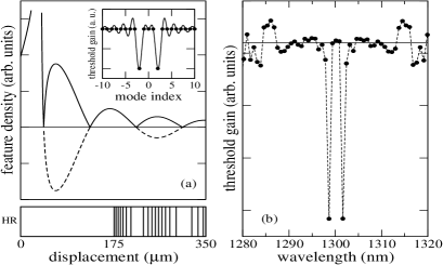
For the two-color device considered the cavity is asymmetric with one larger facet reflectivity . This allows a more uniform density of features along one side of the device center. Once the feature density function is sampled correctly, feature positions are adjusted in order to satisfy the correct phase requirement for resonance. A schematic picture of the device, high-reflection coated as indicated, is shown in the lower panel of Fig. 2. With respect to the lasing wavelength of mode in the cavity, where , the phase requirement corresponds to forming a halfwave resonant subcavity between the corresponding feature and the high-reflection coated mirror. For , we form a quarterwave subcavity at the same wavelength. In this way, at each zero of the feature density function a phase shift is introduced into the index pattern along the device length. Optical path corrections due to the introduction of the features must also be accounted for when the final feature positions are calculated. The calculated form of the threshold gain spectrum is shown in Fig. 2 (b) and is an excellent approximation of the ideal form. To appreciate the simplicity of this approach, it is important to note that the device comprises a single, patterned amplifying section with both external mirrors necessary to form the FP mode structure. Thus, unlike distributed feedback approaches, the role of the inhomogeneous cavity effective index is simply to discriminate between the various FP modes.
We now present experimental measurements of a ridge waveguide FP laser fabricated to the design depicted in Fig. 2. The device is a multi-quantum well InP/InGaAlAs laser of length 350 m with a peak emission near 1.3m. The additional features are slotted regions etched into the laser ridge waveguide. This technique is based on standard optical lithography and does not require a regrowth step. The laser was temperature stabilised at 250C to C and a constant current was applied to the device. Laser emission was spectrally resolved using an optical spectrum analyser with 0.01 nm resolution.
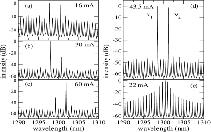
A series of spectra of the device of Fig. 2 are shown in Fig. 3. Fig. 3 (a) shows the device spectrum below threshold. One can see that the two primary modes are already selected in this regime. Note the good agreement with the calculation shown in Fig. 2, with the two primary modes separated by four fundamental FP modes. As the current is increased the mode on the short wavelength side reaches threshold first (Fig. 3 (b)) and as the current is increased further thermal effects lead to the peak power shifting across the primary mode spacing to the long wavelength side (Fig. 3 (c)). The lasing spectrum at 43.5 mA is shown in Fig. 3 (d). At this current the time averaged optical power in the primary modes is approximately equal. For comparison, an above threshold spectrum from a plain FP laser fabricated on the same bar is shown in Fig. 3 (e).
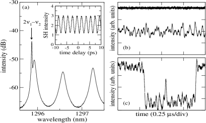
In Fig. 4 (a) we have plotted a higher resolution picture of part of the spectrum of Fig. 3 (d). One can see sideband formation due to four wave mixing (FWM) processes in the cavity. FWM is a third order nonlinear process which occurs due to the formation of a dynamic grating in the material complex index shen ; park . The grating is formed through the beating of the primary modes at and as shown in Fig. 3 (d). The sideband shown appears at a frequency of with the scattering of the primary mode at by the grating. Within the bandwidth of the inverted semiconductor, the patterned FP cavity naturally provides gain and resonant feedback for the FWM sideband, which is slightly detuned from the amplified spontaneous emission peak due to the material dispersion and is resonantly enhanced as the two primary modes attain equal time averaged intensity. The presence of a large, narrow linewidth signal, implies that the two modes are oscillating simultaneously with good phase stability.
Phase coherence of the primary modes implies an ultrafast intensity modulation of the laser output. We measured this mode beating in the cw output of the laser at the difference frequency, GHz. The result of the background free intensity autocorrelation measurement is shown in the inset of Fig. 4 (a) where the contrast ratio observed is close to the theoretical limit of 3:1. In the mode locking regime, the extension of concepts described here to create a comb of discrete wavelengths can lead to compact sources of pulsed radiation with THz repetition rates. In fact, the polarization associated with the mode beating itself is a source of direct THz radiation, generated by the two primary waves in an intracavity process hoffmann . In an intracavity process a single material system simultaneously acts as the pump medium and nonlinear mixing material. Such systems have received considerable interest on account of their potential to enhance nonlinear interactions. Approaches to intracavity wavemixing have tended to focus on engineering of the semiconductor heterostructure to support distinct optical transitions and thus multiple lasing wavelengths capasso ; belyanin . By using the extension of the FP cavity concept described here to suppress unwanted longitudinal cavity mode structure, the efficiency of such approaches can be further improved.
We now apply the classical theory of a homogeneously broadened two mode laser to our device near the current of Fig. 3 (d). In classical laser theory, simultaneous lasing of two modes is possible if the net gain of each mode is positive and the competition due to cross-saturation is sufficiently weakened by a large mode spacing and by the spatial hole burning effect associated with the standing waves of the FP cavity sargent .
Measurement of a large intensity modulation at the difference frequency of the two modes indicates that the device is not exhibiting the mode hopping behaviour characteristic of multiwavelength semiconductor lasers with strongly coupled lasing modes hioe . We confirmed this by measurements of time traces of the modal and total intensity output of the two-color device as shown in Fig. 4 (b). We observe an essentially constant total output and anticorrelated, enhanced intensity noise traces in each of the two primary modes due to mode partition (a single modal intensity time trace is shown for clarity) agrawalpra . The plain FP laser of Fig. 3 (e) also shows a constant total intensity, but analysis of individual modal intensities reveals complex dynamics including mode hopping behaviour, an example of which is shown in Fig. 4 (c). This figure shows a sequence of spontaneous switching events where the longitudinal mode in question switches between an “on” state with large intensity to an “off” state with an intensity close to zero.
In the two-color device here, the coupling between the primary modes is determined by various processes that have different strengths depending on the separation between the modes. These include static spectral hole burning, intraband population pulsations and carrier density pulsations. Because the characteristic time associated with interband processes is large, the contribution of asymmetric nonlinear gain due to the interband carrier density pulsations will be much smaller in the two-color device, where the separation between modes is large. If we neglect the asymmetric contribution, weak coupling of modes in the two-color device requires , where and is the intraband relaxation time ogita . An estimated range of values for is 100 - 200 fs, which determines a minimum spacing for the two modes of 460-920 GHz. Although this estimate is in agreement with the actual modal separation and stability properties observed, a systematic study of two-color and other multiwavelength FP lasers will be of interest in order to understand separately the roles of the primary mode spacing and the total mode number in determining the stability and dynamical properties of this family of devices.
In conclusion, we have introduced a class of multiwavelength Fabry-Pérot lasers where the number and spacing of the lasing modes is limited only by the bandwidth of the active medium. Measurements of simultaneous lasing in a specially designed two-color Fabry-Pérot cavity geometry with THz mode spacing were presented. The inverse scattering approach to multiwavelength laser design described is likely to open up new avenues for the fundamental studies of semiconductor laser stability and dynamics. In addition, the devices can provide interesting and novel solutions to many applied problems in optoelectronics and nonlinear optics.
Acknowledgments. This work was supported by Science Foundation Ireland. The authors thank Guillaume Huyet and John Houlihan for helpful discussions.
References
- (1) G. P. Agrawal and N. K. Dutta, Long-Wavelength Semiconductor Lasers (Van Nostrand Reinhold, New York, 1986).
- (2) H. Kogelnik and C. V. Shank, Appl. Phys. Lett. 18, 152 (1971).
- (3) H. Haken, Laser Theory (Springer-Verlag, Berlin, 1986) (1984).
- (4) A. Tredicuicci, C. Gmachl, F. Capasso, D. L. Sivco, A. L. Hutchinson and A. Y. Cho, Nature (London) 396, 350 (1998).
- (5) M. Yamada, J. Appl. Phys. 86, 81 (1989).
- (6) A. Uskov, J. Mork, J. Mark, M. C. Tatham and G. Sherlock, Appl. Phys. Lett. 65, 944 (1994).
- (7) S. Ogita, A. J. Lowery and R. S. Tucker, J. Quantum Electron. 33, 198 (1997).
- (8) M. Ahmed and M. Yamada, J. Quantum Electron. 38, 682 (2002).
- (9) A. M. Yacomotti, L. Furfaro, X. Hachair, F. Pedaci, M. Giudici, J. Tredicce, J. Javaloyes, S. Balle, E. A. Vikorov and P. Mandel, Phys. Rev. A 69, 053816 (2004).
- (10) S. O’Brien and E. P. O’Reilly, Appl. Phys. Lett. 86, 201101 (2005).
- (11) S. O’Brien, A. Amann, R. Fehse, S. Osborne, E. P. O’Reilly and J. M. Rondinelli, J. Opt. Soc. Am. B in press (2006).
- (12) M. Sargent, M. Scully and W. Lamb, Laser Physics (Addison-Wesley, Reading, Massachusetts, 1974).
- (13) Y. R. Shen, The Principles of Nonlinear Optics (Wiley, New York, 1984).
- (14) I. Park, I. Fischer and W. Elsäßer, Appl. Phys. Lett. 84, 5189 (2004).
- (15) S. Hoffmann, M. Hoffmann, E. Brundermann, M. Havenith, M. Matus, J. V. Moloney, A. S. Moskalenko, M. Kira, S. W. Koch, S. Saito and K. Sakai, Appl. Phys. Lett. 84, 3585 (2004).
- (16) N. Owschimikow, C. Gmachl, A. Belyanin, V. Kocharovsky, D. L. Sivco, R. Colombelli, F. Capasso and A. Y. Cho, Phys. Rev. Lett. 90, 043902 (2003).
- (17) A. A. Belyanin, V. Kocharovsky, V. Kocharovsky and M. Scully, Phys. Rev. A 65, 053824, (2002).
- (18) F. T. Hioe and S. Singh, Phys. Rev. A 24, 2050 (1981).
- (19) G. P. Agrawal, Phys. Rev. A 37, 2488 (1988).