Opto-fluidic third order distributed feed-back dye laser
Abstract
This letter describes the design and operation of a polymer-based
third order distributed feed-back (DFB) microfluidic dye laser.
The device relies on light-confinement in a nano-structured
polymer film where an array of nanofluidic channels is filled by
capillary action with a liquid dye solution which has a refractive
index lower than that of the polymer. In combination with a third
order DFB grating, formed by the array of nanofluidic channels,
this yields a low threshold for lasing. The laser is
straight-forward to integrate on Lab-on-a-Chip micro-systems where
coherent, tunable light in the visible range is desired.
pacs:
42.55.Mv, 42.60.-v, 42.82.Cr, 47.55.nb, 47.61.-k, 47.85.mdIntegration of optical and fluidic functionalities on a chip has recently been investigated by several research groups to realize novel opto-fluidic laser devices, microfluidic dye lasers, suitable for Lab-on-a-Chip micro-systems Helbo et al. (2003); Balslev and Kristensen (2005); Vezenov et al. (2005); Li et al. (2006). These optically pumped devices consist of microfluidic channels with an embedded optical resonator and a liquid laser dye is used as active gain medium. In general, these devices can be added to a microfluidic chip without adding additional fabrication steps Balslev et al. (2006a), thus offering a simple way of integrating optical transducers to Lab-on-a-Chip micro-systems Verpoorte (2003), and pave the way for advanced integrated sensor concepts Lindvold and Lading (2003).
The threshold for lasing is a key parameter for the feasibility of these devices in a future technology. Distributed feed-back (DFB) laser resonators have proven particularly suited in this respect. A DFB microfluidic dye laser was first demonstrated by Balslev and Kristensen Balslev and Kristensen (2005), who used a high order Bragg grating in an thick polymer film to obtain feed-back. Single mode lasing with a threshold fluence of approximately was obtained due to mode selective losses in the multi-mode structure where light was not guided in the fluidic segments. Vezenov et al. Vezenov et al. (2005) obtained liquid-core waveguiding using a low refractive index polymer and a high refractive index liquid. Li et al. Li et al. (2006) exploited this concept to realize a 15th order DFB laser with a record-low threshold fluence for lasing of approximately .
However, the 15th order Bragg grating still gives rise to scattering of light out of the chip plane Hunsperger (2002). These losses can be reduced by employing a lower order Bragg grating. Ideally, a first order Bragg grating combined with planar waveguiding in the polymer film could be used. The requirement of a high refractive index liquid and low refractive index polymer Vezenov et al. (2005); Li et al. (2006) may be relaxed by reducing the dimensions of the resonator segments as the sub-wavelength regime is entered Lalanne and Hutley (2003).
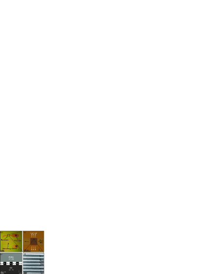
In this Letter, we present the design and operation of a polymer-based third order DFB microfluidic dye laser. The device is fabricated by a flexible lithography technique, combining electron beam lithography (EBL) and UV lithography (UVL) in a single polymer film, enabling fast prototyping of device designs. In the device, see Fig. 1, a third order DFB resonator is formed by infiltrating a periodic array of nanofluidic channels with a liquid laser dye. The filling is mediated by capillary action, thus simplifying the operation of the device as opposed to conventional setups with external syringe pumps. Replenishing of the dye in the cavity region is achieved for hours through capillary filling of a long 100 m wide meandering channel following the cavity region. The speed of the advancing fluid front in the meandering channel decreases with time Tas et al. (2004). The dye solution in the cavity region is replaced in 30 s – 5 min. during the first 30 min. of experiments (ethylene glycol solution). The flow rate in the 500 m 500 m cavity region can be further increased by increasing the width of the meandering channel. By employing a third order Bragg grating, we demonstrate lasing with a threshold fluence comparable to the results of Li et al. (2006). The sub-wavelength dimensions of the third order DFB grating yield a low coupling loss for the light when traversing the dye filled nanofluidic channels, and combined with the feed-back of the DFB grating, this yields an efficient laser device.
The laser is based on a planar waveguide structure supporting a single propagating TE-TM mode. The basic waveguide structure consists of a SiO2 (refractive index ) buffer substrate, a 300 nm thick core layer of the negative-tone resist SU-8 () and a top cladding of poly-methylmethacrylate (PMMA) (). The device structure is formed by nanofluidic channels defined lithographically in the SU-8 film. The laser resonator consists of an array of 300 nm high nanochannels of period which comprises a third order Bragg grating with a central phase-shift, embedded in a wide shallow nanochannel.
To fabricate the devices, a 430 nm thick film of SU-8 2000 resist mic is spin-coated onto a Si substrate with a thick thermally grown oxide layer. The wafer is baked at 90∘C for 1 min. The device structure is defined by combined EBL and UVL in the SU-8 film. The nano-structures of the third order DFB grating are defined by 100 kV electron beam exposure (JEOL-JBX9300FS, dose ). The total writing time for all 32 devices on a 4” wafer is 15 min. After electron beam exposure, the micron-sized structures (meandering channel and reservoirs) are defined in the same polymer film by UV exposure (20 s at ), the wafer is post-exposure baked at 90∘C for 1 min., and the micro and nano-structures are developed simultaneously in propylene glycol monomethyl ether acetate (PGMEA) for 30 s, followed by an iso-propyl alcohol (IPA) rinse. The wafer is subsequently subjected to a 20 s soft oxygen plasma Bilenberg et al. (2006) to remove any residues of SU-8 at the SiO2 surface in the nano-channels of the DFB resonator. After the plasma treatment, the structures are 300 nm high, and the heights of the EBL and UVL defined structures are matched within 30 nm. Fluidic access holes are formed by micro powder blasting dan and the channels are sealed by a glass lid, using adhesive bonding by means of a thick PMMA film (2200 N, 140∘C, 10 min.) Bilenberg et al. (2004).
The laser is characterized by adding a droplet of dye solution to the fluid inlet, thus filling the DFB resonator structure by capillary action. In this Letter, the laser dye Rhodamine 6G (R6G) is dissolved in ethylene glycol (), ethanol (), and in a 1:1 mixture of ethylene glycol and benzyl alcohol ( by experimentally confirmed linear extrapolation of the refractive indices), all with a concentration of and a refractive index below that of the polymer surrounding the channel. The laser is optically pumped through the glass lid by a frequency doubled Nd:YAG laser at 532 nm (5 ns pulse duration, 10 Hz repetition rate).

Fig. 2 shows laser spectra from four different chips filled with R6G in ethylene glycol. The results demonstrate wafer-scale spectral reproducibility of the laser, exhibiting narrow-linewidth emission, polarized perpendicularly to the chip plane (TM). The average laser wavelength is 582.72 nm with a standard deviation of 0.14 nm, at the resolution limit of our spectrometer (0.15 nm). The deviation and the minor peaks in Fig. 2(c),(d) may arise from grating imperfections due to fabrication defects. Due to limited spectrometer resolution, our equipment does not allow us to determine whether the laser is truly operating in a single mode, and the spectral shape and linewidth of the laser remain undetermined.

Fig. 3 shows laser spectra from chips with R6G dissolved in different solvents, thus demonstrating tunability of the laser from 581.41 nm to 587.86 nm. A quantitative theoretical prediction of the shift in wavelength requires a full solution of Maxwell’s equations in the fabricated structure, since the structures are of sub-wavelength dimensions Lalanne and Hutley (2003). In Fig. 3(c), the minor side-mode shifted 1.8 nm from the main peak may be attributed to an additional phase-shift introduced in the DFB grating by a stitching error during electron beam exposure. The dye laser output power is found by integrating the measured laser spectrum for each value of the average pump pulse fluence. The dye laser output power vs. average pump pulse fluence follows the standard pump/output relation of two linear segments around a lasing threshold fluence .
The coupling loss for a period of the DFB grating has been modelled by a finite-difference beam propagation method Balslev et al. (2006b); Hoekstra et al. (1992). Light of the observed wavelength travelling in the TM mode of the single mode polymer waveguide is propagated through a 273 nm wide channel filled with a liquid of refractive index , corresponding to the value of the used solvent. The calculations yield the energy propagation loss corresponding to the coupling loss for a period of the DFB grating. The loss decreases for increasing , see Table 1. To obtain lasing in the resonator, the amplification of the R6G must equal the loss. As expected, the experiments show that the threshold fluence for lasing decreases as the refractive index of the R6G solution increases, see Table 1. Further, when considering the absorbed pump energy throughout the device, the effective threshold fluence may be considerably lower.
In summary, we have demonstrated a third order DFB microfluidic dye laser with a low threshold for lasing and operating with liquids of refractive index below the refractive indices of the surrounding polymer. Although experimental uncertainties make a direct comparison of lasing thresholds difficult, our results imply the importance of both liquid core waveguiding Li et al. (2006) and low order Bragg reflection. The device relies on light-confinement in a nano-structured polymer film where the individual resonator elements – nanofluidic channels and polymer walls – are of sub-wavelength dimensions. The resonator consists of an array of nanofluidic channels forming a third order DFB Bragg grating resonator. The laser is realized using a flexible fabrication technique, combining electron beam lithography and UV lithography in a single polymer film, followed by adhesive polymer wafer bonding. The laser is straight-forward to integrate on Lab-on-a-Chip micro-systems, e.g. for integrated sensors, where coherent, tunable light in the visible range is desired.
The authors thank S. Balslev and N. A. Mortensen for fruitful discussions on the work presented in this Letter.
| Solvent | /nm | |||
|---|---|---|---|---|
| Ethanol | 1.33 | 581.41 | 65 | .191 |
| Ethylene glycol | 1.43 | 582.72 | 40 | .089 |
| Ethylene glycol/ | 1.485 | 587.86 | 10 | .043 |
| benzyl alcohol |
References
- Helbo et al. (2003) B. Helbo, A. Kristensen, and A. Menon, J. Micromech. Microeng. 13, 307 (2003).
- Balslev and Kristensen (2005) S. Balslev and A. Kristensen, Opt. Express 13, 344 (2005).
- Vezenov et al. (2005) D. V. Vezenov, B. T. Mayers, R. S. Conroy, G. M. Whitesides, P. T. Snee, Y. Chan, D. G. Nocera, and M. G. Bawendi, J. Am. Chem. Soc. 127, 8952 (2005).
- Li et al. (2006) Z. Li, Z. Zhang, T. Emery, A. Scherer, and D. Psaltis, Opt. Express 14, 696 (2006).
- Balslev et al. (2006a) S. Balslev, A. M. Jorgensen, B. Bilenberg, K. B. Mogensen, D. Snakenborg, O. Geschke, J. P. Kutter, and A. Kristensen, Lab. Chip 6, 213 (2006a).
- Verpoorte (2003) E. Verpoorte, Lab. Chip 3, 42N (2003).
- Lindvold and Lading (2003) L. Lindvold and L. Lading, in Proceedings of SPIE (2003), vol. 3276, pp. 220–227.
- Hunsperger (2002) R. G. Hunsperger, Integrated Optics: Theory and Technology (Springer-Verlag, Berlin, 2002), 5th ed.
- Lalanne and Hutley (2003) P. Lalanne and M. Hutley, in Encyclopedia of Optical Engineering (Dekker, New York, 2003), pp. 62–71.
- Tas et al. (2004) N. R. Tas, J. Haneveld, H. V. Jansen, M. Elwenspoek, and A. van den Berg, Appl. Phys. Lett. 85, 3274 (2004).
- (11) SU-8 formulation 2002 from MicroChem. Corp., www.microchem.com, diluted with pure cyclopentanone to a 13wt% solid content solution.
- Bilenberg et al. (2006) B. Bilenberg, S. Jacobsen, M. S. Schmidt, L. H. D. Skjolding, P. Shi, P. Boggild, J. O. Tegenfeldt, and A. Kristensen, Microelectron. Eng. 83, 1609 (2006).
- (13) Microetcher II, Danville Engineering, www.daneng.com.
- Bilenberg et al. (2004) B. Bilenberg, T. Nielsen, B. Clausen, and A. Kristensen, J. Micromech. Microeng. 14, 814 (2004).
- Balslev et al. (2006b) S. Balslev, A. Mironov, D. Nilsson, and A. Kristensen, Opt. Express 14, 2170 (2006b).
- Hoekstra et al. (1992) H. J. W. M. Hoekstra, G. J. M. Krijnen, and P. V. Lambeck, J. Lightwave Technol. 10, 1352 (1992).