Electrodynamic trapping of spinless neutral atoms with an atom chip
Abstract
Three dimensional electrodynamic trapping of neutral atoms has been demonstrated. By applying time-varying inhomogeneous electric fields with micron-sized electrodes, nearly strontium atoms in the state have been trapped with a lifetime of 80 ms. In order to design the electrodes, we numerically analyzed the electric field and simulated atomic trajectories in the trap, which showed reasonable agreement with the experiment.
pacs:
32.60.+I, 32.80.Pj, 39.25.+kCoherent manipulation of atoms or ions in the vicinity of solid surfaces has attracted increasing interest as a promising tool for quantum information processing (QIP), because of their potential scalability and controllability of atoms or ions that work as qubits Wineland ; Cirac ; Schmidt-Kaler ; Leibfried . So far, two approaches, i.e., magnetic manipulation of atoms with miniaturized wire traps Fortagh ; Haensch and miniature Paul traps Wineland for ions, have been demonstrated. Recent experiments, however, have witnessed that coherence time of these trapped atoms or ions was shortened by electro-magnetic interactions caused by thermal magnetic fields B ; Harber ; Leanhart ; Lin or fluctuating patch potentials Turchette appeared on the surface if the distance between the particle and the surface become smaller than 100 m. To avoid these harmful influences and have a lifetime nearly a second, paramagnetic atoms need to be more than tens of microns apart from metal surfaces at room temperature B ; Leanhart ; Harber ; Lin . A reported heating rate of ions Turchette indicated stronger coupling of trapped ions to surface potentials than that of neutral atoms.
It has been pointed out that the best candidates for long-lived trap are spinless neutral atoms, which weakly interact with stray fields via the Stark effect Henkel ; Henkel2 . Alternatively, material dependence of the trap lifetime has been investigated to reduce thermal magnetic field in magnetic atom-chips Harber ; Lin ; Sinclair . Electric manipulation of atoms, which allows manipulating spinless neutral atoms in addition to paramagnetic atoms and molecules, may open up a new possibility for scalable quantum systems with long coherence time. In this Letter, we demonstrate three dimensional (3D) electrodynamic trapping of laser cooled Sr atoms in the state with miniature electrodes fabricated on a glass plate. The very thin electrodes ( nm) used in the experiment will significantly reduce thermal magnetic fields near metal surfaces, which would be especially profitable in applying this scheme to paramagnetic atoms.
For an applied electric field , the Stark energy is given by . Since the static dipole polarizability is positive for atoms in stable states, these atoms can be trapped at a local maximum of the electric field strength and behave as a “high-field seeker”. However, as the Laplace equation does not allow an electrostatic field to form a maximum in free space, 3D trapping is not possible for a static electric field alone Wing . In addition owing to a small dipole polarizability, rather high electric fields are required for the Stark manipulation of laser-cooled atoms: So far 1D or 2D focusing/trapping experiments Shimizu_2Dtrap ; Salomon ; Noh have been demonstrated by applying several to ten kV to electrodes with dimensions of a few mm. A dynamic stabilization scheme, as employed in RF ion traps, allows electric trapping with higher dimensions. Electrodynamic 2D focusing of atoms Shimizu_2Dtrap and guiding of molecules Rempe were demonstrated by using 4 rods with oscillating voltages. 3D trapping by 3 phase electric dipole fields Shimizu_etrap or by an oscillating hexapole field superimposed on a static homogeneous field Peik has been proposed. The latter scheme has recently been demonstrated in trapping cold polar molecules Meijer .
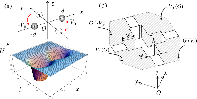
Here we consider 3D electrodynamic trapping with two-phase electric-dipole field, which will allow planar geometry that is suitable to be used with atom chips Katori_e-trap . In order to illustrate the scheme, we first assume two spherical electrodes with radius placed at either on the (or ) axis, kept at voltages as shown in Fig. 1(a). The corresponding Stark energy (or ) for an atom near the origin is calculated in the lowest order of ,
| (1) |
where is the atomic mass, is the trapping frequency of an atom perpendicular to the dipole axis. The axial symmetry of electrodes determines and . The static dipole polarizability of Hyman for Sr atoms in the ground state is used in the calculation. While both of the potentials and provide static confinement along the axis, they form saddle potential in the -plane. The 3D trapping, therefore, can be realized by dynamically stabilizing atomic trajectories in -plane by alternating these two potentials. In Eq. (1) anharmonic terms higher than , where and stand for coordinate, are neglected. However, as discussed later, these terms play crucial role in determining the effective trap volume.
By switching the charge distribution between and axis at a period of , the time-dependent Stark potential is given by
| (4) |
where is an integer. The time evolution of the position and velocity of an atom subjected to can be described by transfer matrices Ion_Mathieu ; Noh , whose eigen-values of guarantee stable trapping. Harmonic approximation of the Stark potential as given in Eq. (1) is used to determine the stability of the trap with respect to the driving frequency . For the electrodes configuration with (and ) as discussed above, the stability regime is calculated to be Katori_e-trap (see Fig. 2(a)). This narrow stability regime for , however, made experiments rather challenging.
The stability regime on can be extended by reducing the normalized strength of the anti-trapping potential, as shown by a gray area in Fig. 2(a). Wider driving frequency range can be obtained for close to unity, which is realized by applying line charges instead of point charges. Figure 1(b) depicts a model for designing actual electrodes, where shaded parts are made of conducting material and the other parts insulator. When voltages are applied to four rectangular parallelepiped electrodes with diagonal separation of and thickness of , most of the charges distribute at the ridge of the electrodes. Therefore the Stark potential can be approximated by line charges of length .
We numerically analyzed the electric field produced by these electrodes by employing the finite element method (FEM). Figure 2(b) shows the normalized strength of the anti-trapping potential (filled circles) and that of the static potential (empty circles) as a function of the electrode thickness , where channel width of m was assumed. For thinner electrodes, and were obtained in agreement with the case of two point charges Katori_e-trap because the charge distributes at the tip of the electrode. By increasing the thickness of the electrodes, while the trapping frequency along -axis becomes weaker, approaches to unity and wider stability region can be obtained, as expected for the two dimensional atom guide Shimizu_2Dtrap ; Rempe .
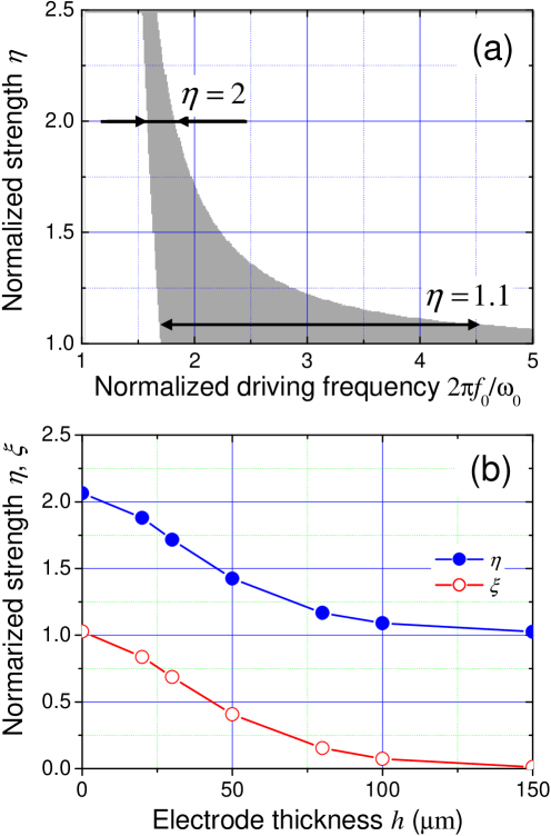
Considering these trade-offs, we designed the thickness of the electrodes as =100 m for m, which provided (see Fig. 2(b)). By applying voltages of V to the electrodes, kHz and kHz along -axis were obtained. The latter is strong enough to support atoms against gravity even when -axis directs vertically. The electrode assembly was made on a 100-m-thick fused-silica substrate of 1 inch diameter, which was first coated with 250 nm thick silver on both sides. A cross through-hole and electrode pattern were fabricated by Focused Ion Beam (FIB) process. Side-walls of the hole were then coated with 40-nm-thick silver to form four electrodes. Figure 3(a) shows a scanning ion microscope (SIM) image of the atom chip.
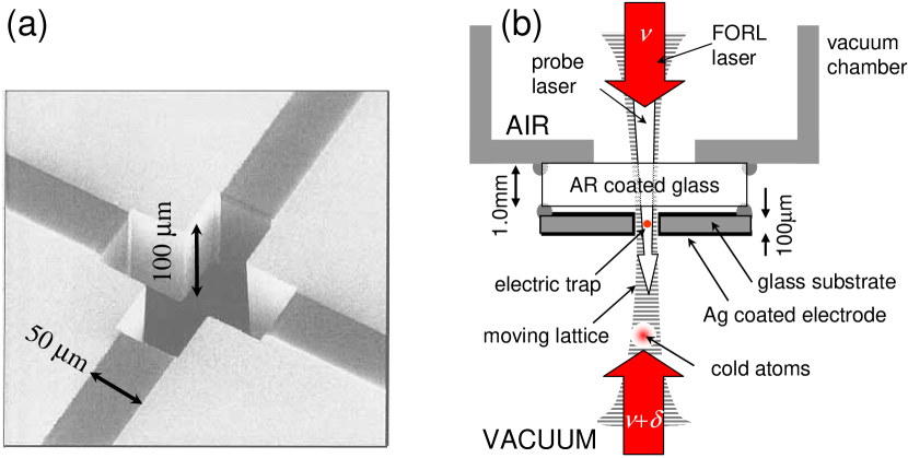
An electrodynamic trapping experiment was performed in four steps, in less than a second: (1) Laser cooling and trapping of 88Sr atoms, (2) transport of atoms into an electric trap, (3) electrodynamic trapping, and (4) detection of trapped atoms. A schematic of an experimental setup is shown in Fig. 3(b). We cooled and trapped more than atoms at several K in 0.6 s by using magneto-optical trap (MOT) on the spin-forbidden transition at nm Katori . Silver surfaces of the electrodes as shown in Fig. 3(a) were used as a mirror to perform a mirror MOT Haensch , in which the trapped atom cloud was located 1.5 mm below the mirror surface. This electrode assembly, or the “Stark chip” was glued on a 1-mm-thick vacuum view port with a clear aperture of 8 mm. The vacuum pressure was typically Torr during the experiment.
The atoms were then loaded into a one dimensional far-off-resonant optical lattice (FORL) formed by a pair of counter-propagating lasers at nm Katori1999 . These lasers were focused onto the center of the through hole of the Stark chip. The waist radius was set to 16 m so as to have the Rayleigh length of 1 mm to reach atoms in the MOT. Laser intensity of 100 mW per beam was chosen to provide a lattice potential with a radial confinement frequency of at the chip center, which was close to a secular frequency of the electric trap as described below and allowed a good mode matching in atom loading into the electric trap. By changing the frequency of one of the lattice lasers Salomon_ML , we adiabatically transported atoms into the atom chip in 6.8 ms. The transported atomic cloud inside the electrode gap had a temperature of about 7 K and a radius of .
Turning off the lattice lasers, the electrodynamic trapping was started by applying V onto the diagonal electrodes (see Fig. 1(b)) at a driving frequency of kHz, which gave a secular frequency of kHz. After a certain trapping time, the electric trap was switched off. Using the moving lattice, we extracted the atoms 0.28 mm below the chip to observe trapped atoms. We illuminated them with a 10-s-long probe laser resonant to the transition at nm. The fluorescence was imaged onto an Intensified CCD (ICCD) camera to measure the number of trapped atoms with an uncertainty of 10 .
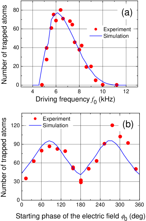
Filled circles in Fig. 4(a) show the number of trapped atoms as a function of the driving frequency for a trapping time of 5 ms. We have performed numerical integrations of the equation of motion of an atom subjected to the alternating electric fields Katori_e-trap that were calculated by the FEM for the electrode configuration shown in Fig. 1(b). Taking the initial atom temperature and its spatial distribution as used in the experiment, the calculation (solid line) well reproduced the experiment, where the amplitude (atom number) was used as a fitting parameter.
As mentioned earlier the stability of the miniaturized electric trap is crucially affected by the anharmonicity of the trapping potential, since the Stark potential provided by the dipole electric field contains relatively-large higher-order terms FEM . These terms limit the effective trap diameter 2 to be typically one fifth of the electrode separation as determined by numerical simulation Katori_e-trap . This limited trapping volume, in turn, makes the capture velocity of the trap be dependent on a starting phase of electric trapping field. Atoms with an outward velocity toward a particular direction, say -axis, need to be decelerated by the driving field before reaching by the end of the trapping-phase, while the similar but out of phase discussion applies for the atomic motion in -axis that is in the anti-trapping phase. We defined when the Stark potential was switched at as given in Eq. (2), i.e., for the -th driving period, and studied the starting phase dependent trap efficiency as shown in Fig. 4(b). The number of trapped atoms (filled circles) was in reasonable agreement with a numerical simulation (solid line), where the amplitude (atom number) was used as an adjustable parameter, indicating that the best loading is realized for the trapping field started at or 270∘. In the experiment, a slight asymmetry in the peak heights was observed. This may be attributed to spatial offset of an initial atomic cloud with respect to the trap center, which was possibly caused by misalignment of the FORL lasers. We have measured the lifetime of atoms in the electric trap to be 80 ms, which was in reasonable agreement with glancing-collisions-limited lifetime Bjorkholm1988 assuming the background gas pressure of Torr in the electrode gap. Note that similar lifetime was observed for atoms in the FORL, when its trap depth was comparable to that of the electric trap (K).
In applying atom-traps to QIP experiments, qubit states should experience the same trapping potential so as to minimize decoherence caused by atomic motion Katori2003 ; Haroche2004 . For example, in the case of this Stark trap, Zeeman substates of the metastable state, which has a lifetime over 100 s Yasuda2004 , can be used as a qubit state that experience the same Stark shift. Although the coherent evolution of these states may be disturbed by the thermal magnetic fields that appeared on the electrodes surfaces, a very thin electrode (40 nm) demonstrated here may significantly reduce thermal magnetic fields that cause spin flips Henkel ; Henkel2 , since the Johnson noise induced currents decrease as electrode’s thickness Lin . Furthermore, since the operation of the electrodynamic trap relies on switching of electric fields, it is free from ohmic dissipation and allows dense integration of traps. Array of electrodes, four of which activated in turn so as to adiabatically transfer atoms, may constitute atom wave guide that is reminiscent of the quantum CCD Kielpinski .
In conclusion, we have investigated the design of electrodes with a help of numerical simulation and demonstrated an electrodynamic trapping of spinless neutral Sr atoms with micron-sized structures. By reducing the electrode size to a few m, these atom traps can be driven by a few volts Katori_e-trap , which will make electric atom traps compatible with electronic logic circuits, offering an interface between atom manipulation and electronics.
The authors would like to thank A. Yamauchi, and M. Tange for their technical support.
References
- (1) [] Present address: †Institute of Engineering Innovation, The University of Tokyo, Bunkyo-ku, Tokyo 113-8656, Japan, ‡National Metrology Institute of Japan (NMIJ/AIST), Tsukuba, Ibaraki 305-8563, Japan.
- (2) ∗E-mail: katori@amo.t.u-tokyo.ac.jp
- (3) D. Leibfried, R. Blatt, C. Monroe, and D. Wineland, Rev. Mod. Phys. 75, 281 (2003).
- (4) J. I. Cirac and P. Zoller, Phys. Rev. Lett. 74, 4091 (1995).
- (5) F. Schmidt-Kaler et al., Nature 422, 408 (2003).
- (6) D. Leibfried et al., Nature 422, 412 (2003).
- (7) J. Fortagh, A. Grossman, C. Zimmermann, and T. W. Hänsch, Phys. Rev. Lett. 81, 5310 (1998).
- (8) J. Reichel, W. Hänsel, and T. W. Hänsch, Phys. Rev. Lett. 83, 3398 (1999).
- (9) M. P. A. Jones, C. J. Vale, D. Sahagun, B. V. Hall, and E. A. Hinds, Phys. Rev. Lett. 91, 080401 (2003).
- (10) A. E. Leanhardt et al., Phys. Rev. Lett. 90, 100404 (2003).
- (11) D. M. Harber, J. M. McGuirk, J. M. Obrecht, and E. A. Cornell, J. Low Temp. Phys. 133, 229 (2003).
- (12) Y. J. Lin, I. Teper, C. Chin, and V. Vuletić, Phys. Rev. Lett. 92, 050404 (2004).
- (13) C. D. J. Sinclair et al., Phys. Rev. A72, 031603(R) (2005).
- (14) Q. A. Turchette et al., Phys. Rev. A61, 063418 (2000).
- (15) C. Henkel and M. Wilkens, Europhys. Lett. 47, 414 (1999).
- (16) C. Henkel, S. Pötting, and M. Wilkens, Appl. Phys. B 69, 379 (1999).
- (17) W. H. Wing, Progr. Quant. Electr. 8, 181 (1984).
- (18) F. Shimizu, in , edited by H. Walther, T. W. Hänsch, and B. Neizert (AIP, New York, 1993).
- (19) P. Lemonde et al., Europhys. Lett. 32, 555 (1995).
- (20) H. -R. Noh, K. Shimizu, and F. Shimizu, Phys. Rev. A 61, 041601(R) (2000).
- (21) T. Junglen, T. Rieger, S. A. Rangwala, P. W. H. Pinkse, and G. Rempe, Phys. Rev. Lett. 92, 223001 (2004).
- (22) F. Shimizu and M. Morinaga, Jpn. J. Appl. Phys. 31, L1721 (1992).
- (23) E. Peik, Eur. Phys. J. D 6, 179 (1999).
- (24) J. vanVeldhoven, H. L. Bethlem, and G. Meijer, Phys. Rev. Lett. 94, 083001 (2005).
- (25) H. Katori and T. Akatsuka, Jpn. J. Appl. Phys. 43, 358 (2004).
- (26) The FEM analysis indicated that the contribution of the higher order terms is on the order of of the total potential energy for an atom at =8 m from the center.
- (27) H. L. Schwartz, Phys. Rev. A. 10, 1924 (1974).
- (28) M. W. Forbes et al., J. Mass Spectrom. 34, 1219 (1999).
- (29) H. Katori, T. Ido, Y. Isoya, and M. Kuwata-Gonokami, Phys. Rev. Lett. 82, 1116 (1999).
- (30) H. Katori, T. Ido, and M. Gonokami, J. Phys. Soc. Jpn. 68, 2479 (1999).
- (31) M. BenDahan, E. Peik, J. Reichel, Y. Castin, C. Salomon, Phys. Rev. Lett. 76, 4508 (1996).
- (32) H. Katori, M. Takamoto, V. G. Pal’chikov, and V. D. Ovsiannikov, Phys. Rev. Lett. 91, 173005 (2003).
- (33) P. Hyafil et al., Phys. Rev. Lett. 93, 103001 (2004).
- (34) J. E. Bjorkholm, Phys. Rev. A38, 1599 (1988).
- (35) M. Yasuda and H. Katori, Phys. Rev. Lett. 92, 153004 (2004).
- (36) D. Kielpinski, C. Monroe, and D. J. Wineland, Nature 417, 709 (2002).