Preprint of:
D. R. Mason, S. J. Goodman, D. K. Gramotnev, and T. A. Nieminen
“Resonant coupling between bulk waves and guided modes in a
dielectric slab with a thick holographic grating”
Applied Optics 45(8), 1804–1811 (2006)
Resonant coupling between bulk waves and guided modes
in a dielectric slab with a thick holographic grating
Abstract
What we believe to be a new type of resonant coupling of an incident bulk wave into guided modes of a slab with a thick holographic grating is shown to occur in the presence of strong frequency detunings of the Bragg condition. This happens through the reflection of the strongly noneigen diffracted order with the slab–grating boundaries, the resultant reflected waves forming a guided slab mode. Rigorous coupled-wave analysis is used for the numerical analysis of the predicted resonant effects. Possible applications include enhanced options for the design of multiplexing and demultiplexing systems, optical signal-processing devices, optical sensors, and measurement techniques.
I Introduction
Resonances and anomalies of scattering of electromagnetic waves in periodic gratings have been extensively analyzed in the past ref1 ; ref2 ; ref3 . This includes resonant generation of guided and surface waves by means of bulk waves interacting with periodic surface-relief gratings ref1 ; ref2 . The associated anomalies of reflection and the strong resonant increase of the scattered wave near the interface were called Wood’s anomalies ref2 ; ref3 . They occur when the scattered wave propagates almost parallel to the interface of the two media with a grating. The recent rapid development of photonics, optical communications, and signal processing has resulted in a strong renewed interest in these anomalies, mainly due to the possibility of using them for the design of multiplexing and demultiplexing devices and coupling of bulk electromagnetic waves to guided or surface modes ref4 . All these effects usually take place in thin gratings of thickness that is smaller than or of the order of the wavelength (e.g., surface-relief gratings with small amplitude).
Recently, several new and unusual resonant effects in thick gratings (of thickness that is much larger than the wavelength) have been predicted theoretically in the geometry of extremely asymmetrical scattering and grazing-angle scattering (GAS), i.e., when the scattered wave propagates parallel5 or almost parallel to the grating boundaries ref6 . In particular, strong GAS resonances have been associated with the generation of a new type of mode in gratings and photonic crystals—grating eigenmodes ref7 ; ref8 ; ref9 ; ref10 . These modes can be guided by a slanted grating alone without conventional guiding effects in the structure ref7 ; ref8 ; ref9 . At the same time, increasing the mean dielectric permittivity inside the grating region, i.e., assuming that the grating is formed in a guiding slab, results in a number of new modes propagating in the slab ref10 . These modes have nothing to do with the conventional guided slab modes—they are generated at wrong angles of scattering and have an unusual field structure inside the slab ref10 .
Grating eigenmodes are formed by all the diffracted orders interacting with each other inside the grating, and thus cannot exist in the absence of the grating ref7 ; ref8 ; ref9 ; ref10 . They appear to be weakly coupled to the bulk incident wave, which results in strong resonances of scattering in the grating at angles that do not correspond to generation of the conventional guided modes ref11 . In fact, grating eigenmodes can exist only if the conventional guided modes are not effectively generated due to large grating amplitude and or grating width, and, vice versa, structures in which conventional guided modes are effectively generated cannot support grating eigenmodes. Therefore grating eigenmodes exist only in sufficiently wide gratings with large amplitude (e.g., in photonic crystals).
Remarkably, grating eigenmodes can exist (and the associated resonances can be very strong) in the presence of strong frequency detunings of the Bragg condition ref9 ; ref12 . In fact, in some structures, the strongest resonances occur when the frequency is almost halfway between the two Bragg frequencies corresponding to the first- and second-order scattering ref9 . However, strong resonances of scattering at frequencies that are strongly detuned from the Bragg frequency normally occur at large grating amplitude (more than % of the mean permittivity in the grating) ref9 . If the grating amplitude is reduced, the resonances disappear and eventually are replaced by resonances caused by the generation of conventional slab modes ref10 .
The aim of this paper is to investigate theoretically a new effect that is associated with strong and sharp resonances in wide holographic gratings in a guiding slab with small grating amplitude and at large (up to %) detunings of the Bragg frequency. Remarkably, it will be shown that the scattered wave is not only strongly noneigen in the slab, but also propagates in a direction that does not correspond to a guided mode of the slab. Nevertheless, the predicted resonances will be explained by generation of the conventional guided modes, but in a peculiar way by means of interaction of the noneigen (due to strong frequency detunings) scattered wave from the slab boundaries.
II Structure and methods
Consider a slanted holographic grating in a thick dielectric slab of width (the wavelength in vacuum) with the dielectric permittivity given as
| (1) |
where is the mean permittivity in the grating region; and are the permittivities in front of and behind the grating, respectively; and (guiding slab); is the grating amplitude; is the reciprocal lattice vector; and , with as the grating period. The system of coordinates is presented in figure 1; all the media are isotropic and nondissipative, and the grating is infinite in the and directions.
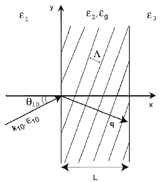
Let a TE electromagnetic wave with amplitude and wave vector (, where is the angular frequency and is the speed of light in vacuum) be incident onto the grating from the left () at an angle with respect to the axis (figure 1). In the rigorous coupled-wave theory, the field inside the grating is represented in the form of a superposition of an infinite number of spatial harmonics (diffracted orders) with -dependent amplitudes ref4 :
| (2) |
and the wave vectors are determined by the Floquet condition ref4 :
| (3) |
where is the wave vector of the incident wave (the 0th diffracted order) in the grating (slab), with .
Substituting equation (2) into the wave equation in the grating gives an infinite set of coupled-wave secondorder differential equations that are then truncated and solved numerically for the amplitudes of the diffracted orders (see, for example, ref4 ). The unknown constants of integration are determined from the boundary conditions at the grating boundaries. If at some frequency and we have , then the Bragg condition is satisfied for the diffracted order, and is called the Bragg frequency (first-order Bragg scattering). In this case, the diffracted order is an eigen bulk wave in the material of the slab. If the frequency is such that , then the Bragg condition is detuned by the value .
In this paper we will investigate the frequency response of thick holographic gratings (described by equation (1)) in a guiding slab. The grating amplitude is assumed to be small, so that the GAS resonances do not occur, and resonant generation of conventional slab modes is expected in the slab. In Section 3, strong anomalies of scattering will be predicted and explained at large (up to %) negative frequency detunings of the Bragg condition, i.e., when the frequency of the wave . Rigorous coupled-wave theory based on the enhanced T-matrix algorithm ref13 will be used for the analysis, although in some cases the approximate coupled-wave theory based on the two-wave approximation ref14 will be sufficient.
III Numerical results
As an example, consider a structure with the following parameters: m; ; ; ; , i.e., (the value of has been chosen so that the critical angle of total internal reflection for a wave propagating inside the layer is equal to ). The Bragg condition is assumed to be satisfied precisely at the frequency rad/s (the corresponding Bragg wavelength in vacuum is m).
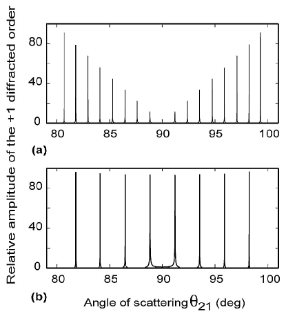
Figure 2 presents the dependencies of the relative amplitude of the scattered wave ( diffracted order) in the grating on the angle of scattering . This is the angle of propagation of the diffracted order in the grating with respect to the axis. The Bragg condition is assumed to be satisfied precisely for all considered angles of scattering, i.e., the slanting angle and the period of the grating are adjusted accordingly for each angle of scattering. The dependencies are presented at the front and rear boundaries of the grating (guiding slab) (figure 2(a)) and in the middle of the grating (slab) (figure 2(b)).
Sharp resonances of scattering can be seen in figure 2, indicating a strong increase of the scattered wave amplitude at several resonant angles of scattering. At these angles, resonant coupling between the incident bulk wave and the modes guided by the slab takes place. The maximums in figure 2(b) represent the symmetric modes of the slab. This is because the electric field of the antisymmetric modes in the middle of the slab is equal to zero (and we do not see the corresponding resonances in figure 2(b)). At the same time, at the slab boundaries, both symmetric and antisymmetric modes have a nonzero electric field. Therefore twice as many maximums can be seen in figure 2(a), corresponding to both symmetric and antisymmetric modes.
The patterns of the resonances are almost symmetric with respect to in figures 2(a) and 2(b). This is because a guided mode in the slab can be represented by a bulk wave successively reflecting from the slab boundaries ref11 . Therefore such a mode can equally be generated by means of coupling of the incident bulk wave into the diffracted order propagating toward the front grating boundary () or toward the rear grating boundary (), as long as this diffracted order propagates at the angle (with respect to either of the slab boundaries) corresponding to a guided mode. Therefore the pattern of resonances is symmetric with respect to . As a result, the eight maximums in figure 2(b) correspond to four different symmetric slab modes (pairs of maximums that are symmetric with respect to correspond to the same mode). Similarly, 16 maximums in figure 2(a) (at the slab boundaries) correspond to four symmetric and four antisymmetric modes. Note, however, that the mentioned symmetry disappears when the thickness of the slab becomes of the order of or less than the wavelength of the incident wave ref15 . In this case, the Bragg regime of scattering is replaced by the Raman–Nath regime ref4 , and it is hardly possible to speak about a slanting angle of the grating fringes with respect to the slab boundaries. This effectively means that the reciprocal lattice vector of the grating is parallel to the slab, rather than pointing at some angle with respect to the grating slab boundaries. As a result, the pattern of the resonances becomes asymmetric with respect to , and the maximum(s) at ref15 .
We emphasize again that thick holographic gratings in a guiding slab resonantly couple the incident radiation into a slab mode if the angle of propagation of the diffracted order (for which the Bragg condition is satisfied) is equal to the angle of propagation of the bulk wave representing the guide mode of the slab.
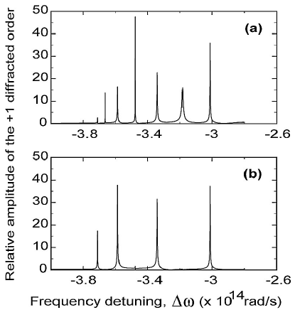
Let us now consider the frequency response of scattering in the thick holographic gratings in a guiding slab. For example, consider the same structure with the thick holographic structure in a slab of thickness m, with ; ; ; , i.e., . However, this time we fix the orientation and the period of the grating so that the Bragg condition for the diffracted order is satisfied precisely at and the angle of scattering is . At the mentioned structural parameters, we change the frequency of the incident wave. The dependencies of the amplitude of the diffracted order on frequency detuning of the Bragg condition are presented in figures 3(a) and 3(b) at the boundaries and in the middle of the slab, respectively.
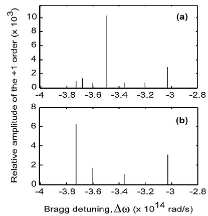
The main unusual features of these dependencies (figure 3) are the strong and sharp resonances of scattering at the frequency detunings that are just 5–6 times smaller than the Bragg frequency rad/s. Note that it is hardly possible to expect any scattering in the grating at the considered small grating amplitude and such large frequency detunings. It is obvious that these resonances must be related to the resonant generation of some type of localized or guided modes in the structure. Further decrease of the grating amplitude results in a rapid increase of the height and sharpness of the considered resonances. However, the angles at which these resonances occur are hardly affected by reducing the grating amplitude. If the grating amplitude tends to zero, then the resonances tend to infinity, which means that the corresponding modes still exist, but they become uncoupled to the incident wave. This demonstrates that these modes can exist in the absence of the grating. Therefore they cannot be a type of grating eigenmode ref7 ; ref8 ; ref9 ; ref10 but must simply be the conventional guided modes of the dielectric slab. This has also been confirmed by considering the field distributions in the grating and slab at the resonant frequency detunings. It can be shown that these distributions are practically identical to those corresponding to the conventional guided modes in the slab. As a result, it can be seen that the resonances in figure 3(b) correspond to the generation of the symmetric modes of the slab, and the additional maximums in figure 3(a) correspond to the antisymmetric modes. In particular, the leftmost peaks in figures 3(a) and 3(b) (at the largest ) correspond to the fundamental guided mode of the slab, and the peaks at smaller detunings represent the higher-order guided modes.
However, there is still a question as to how these slab modes could be generated by the incident wave at the mentioned strong (up to %) frequency detunings of the Bragg condition, when the diffracted order in the grating is expected to be a strongly noneigenwave with the wrong wave vector , (), which does not correspond to a bulk wave propagating in the material of the slab. Moreover, it can be shown that at each of the resonant detunings (figure 3) the angle between the vector and the slab boundaries is significantly different from the angle that one would expect for a guided slab mode. Therefore noneigen oscillations of the electromagnetic field corresponding to the order should be driven by the incident wave in the grating and must rapidly tend to zero if . Such a noneigenwave in the slab cannot form a guided mode. This, however, is in obvious contradiction with the obtained rigorous numerical results (figure 3).
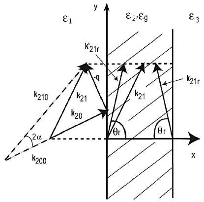
To understand the physical origins of the resonances observed in figure 3, consider figure 4. If (i.e., ), then the wave vector of the incident wave inside the grating and slab is . In this case, we assume that the Bragg condition is satisfied and thus the diffracted order is a propagating eigenwave in the slab. Thus the wave vector of this wave is equal in magnitude to , i.e., (the angle between the vector and the axis is —see above).
Introducing nonzero detunings of the Bragg condition by reducing the frequency of the incident wave by results in reduction of the wave vector of the incident wave (figure 4). At all frequency detunings, the wave vector of the diffracted order is given by the Floquet condition (equation (3)) with . Therefore it can also be seen that if , then , and the angle between the vector and the axis increases with increasing magnitude of the detuning (figure 4).
As mentioned above, the wave vector has a wrong magnitude () and direction (that does not correspond to a guided mode in the slab). The noneigenwave with this wave vector interacts with the slab–grating boundaries and generates a periodic field pattern along these boundaries. According to the Huygens principle, this pattern will generate a reflected bulk wave in the slab with the wave vector (figure 4). The tangential (to the boundaries) component of this vector is equal to the component of the wave vector : (Snell’s law). However, since this reflected wave is not driven by scattering (its wave vector does not satisfy the Floquet condition of equation (3)), it must be either an evanescent wave in the grating (if ) or a propagating eigenwave in the material of the slab (if ). Therefore the component of its wave vector is given as
| (4) |
If this reflected wave is an eigenwave in the slab (i.e., ) and it propagates at an angle that corresponds to one of the guided modes in the slab, then this guided mode will be resonantly generated in the slab (figure 3). Thus the guided modes of the slab in this case are generated by means of the interaction of the noneigen diffracted order with the slab boundaries. Only the presence of the boundaries (structural discontinuities along the axis) results in transformation of the wrong wave vector of the diffracted order in the presence of strong frequency detunings into the correct vector corresponding to a guided slab mode.
Since changing the frequency results in changing the direction of the vector and its magnitude, the corresponding direction of the wave vector of the reflected eigenwave in the slab will also change. Thus, adjusting frequency detuning, we automatically adjust the direction and magnitude of the vector . When the detuning is such that corresponds to a guided slab mode, resonant generation of such a mode occurs (figure 3). The resonant detuning must be strong so as to result in a significant adjustment of the magnitude and direction of the vector. Since the detuning is strong, the amplitude of the noneigen diffracted order in the grating is very small. This means that the coupling of the incident wave into the corresponding slab mode is very weak, which results in very strong and sharp resonances in figure 3. Decreasing the grating amplitude results in a further decrease of the coupling and the corresponding increase of the height and sharpness of the resonances (figure 3). However, the resonant frequency detunings will hardly depend on the grating amplitude, since it does not affect the directions and the magnitudes of the considered wave vectors (figure 4). This is clearly confirmed by the numerical results.
The height of the observed resonances (figure 3) is practically infeasible—it will be hardly possible to achieve such resonances experimentally because this would require very large relaxation times (due to weak coupling). This example has been used to highlight the considered new type of coupling and to demonstrate that the resulting resonances are associated with the conventional guided modes generated in an unusual way by means of reflection of the noneigen diffracted order from the slab boundaries. A more reasonable situation occurs when the grating amplitude is increased () and the corresponding resonances are significantly lower, as shown in figure 5. As can be seen in figure 5, the positions of the resonances are practically the same as in figure 3 with only % reduction of the resonant frequency detunings. This demonstrates very weak dependence of the resonant detunings on grating amplitude. This is expected, since only large grating amplitudes are expected to noticeably change the guiding properties of the slab and the corresponding wave vectors of the slab modes.
The fact that the resonances in figures 5(a) and 5(b) still correspond to conventional guided modes is again confirmed by the analysis of the field distribution in the diffracted order inside the slab at each of the resonant frequency detunings. For example, the obtained field distributions inside that slab for the three leftmost maximums in figure 5(a) are presented in figure 6(a). It can be seen that these distributions are very close to those in the first three conventional modes guided by the slab. Therefore the leftmost maximum in figure 5(a) corresponds to curve 1 in figure 6(a) (fundamental mode of the slab), the second-from-the-left maximum in figure 5(a) corresponds to curve 2 in figure 6(a) (the first antisymmetric mode), etc.
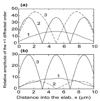
At the same time, it can be noticed that curve 1 in figure 6(a) displays small bumps, which is not a typical feature of the field distribution corresponding to the fundamental slab mode. These bumps become more pronounced with increasing grating amplitude (see figure 6(b) for ). Curve 2 in figure 6(b) also displays similar irregularities (unlike curve 2 in figure 6(a) for ). This is related to the effect of the grating on the guided modes. This effect rapidly increases with increasing grating amplitude (compare figures 6(a) and 6(b)). Eventually, when the grating amplitude becomes sufficiently large, the structures of the guided modes substantially change, and they may be transformed into grating eigenmodes ref7 ; ref8 ; ref9 ; ref10 . Note also that the effect of the grating is more pronounced for lower slab modes (compare the curves in figures 6(a) and 6(b)).
It is also important to note that the reflected wave with the wave vector does not appear explicitly in the coupled-wave expansion of equation (2). Rather, it is formally included in the amplitude of the diffracted order. Indeed, the diffracted order in equation (2) can be represented as
| (5) |
where is the -dependent amplitude of the diffracted order resulting from the direct interaction (scattering) of the incident wave with the grating, and the other two terms in the square brackets are due to the two waves reflected from the rear grating boundary ( with ; see equation (4)) and the front grating boundary (). All three waves have the same components of their wave vectors (Snell’s law, or conservation of the tangential component of momentum), whereas the components are significantly different: , , and , respectively. Because the components of the wave vectors are the same for all three waves, these waves can formally be included in the diffracted order in the expansion in equation (2), which eventually results in a strong resonant increase of the overall amplitude of this order at the resonant frequency detunings (figure 3). Actually, these are the amplitudes and that experience a strong resonant increase at the resonant detunings, whereas the amplitude remains small (it tends to zero as ). In this case, because the amplitudes of the reflected waves become predominant at the resonant detunings, the field distribution inside the grating and slab indeed appears to be almost identical to that in the corresponding slab modes (figure 6).
It is possible to derive analytical equations for the resonant detunings in a slab with a thick holographic grating. For this purpose, we will need to determine the magnitude and components of the wave vectors and . From figure 4, it can be seen that the magnitude of the wave vector is determined by the equation
| (6) |
where is the angle between and the grating fringes (figure 4) and
| (7) |
It follows that, since is the angle between and (figure 4),
| (8) |
It can also be seen that the angle between the two vectors and is determined by the equation
| (9) |
Then the angle between the vector and the axis is
| (10) |
Using equations (6)–(10), we find the component of the wave vector , and thus the components of the vector:
| (11) |
| (12) |
From here, the angle of propagation of the reflected wave (figure 4) is
| (13) |
For example, consider the leftmost peak in figure 3. It corresponds to the frequency detuning rad/s. Using equations (6)–(13), we obtain . The conventional analysis of the guided modes ref11 in the considered slab at the frequency demonstrates that this is exactly the angle of the wave propagation in the slab, which corresponds to the fundamental slab mode. Thus the leftmost maximum in figure 3 corresponds to the resonant generation of the fundamental slab mode at the frequency in an unusual way through the noneigen diffracted order, interacting with the slab boundaries. Using a similar procedure, it can be shown that the other resonances in figure 3 are associated with the generation of higher slab modes by means of the same mechanism.
It is important to note that, as can be seen from figure 4, an increase in the magnitude of the frequency detuning (i.e., a reduction of ) results in an increase in the angle . This is the reason why the resonance associated with the generation of the lower-order guided modes (corresponding to larger angles ) is found at larger detunings (figures 3 and 5).
It is also important to emphasize that the considered effect of resonant coupling at strong resonant frequency detuning occurs in a wide range of angles of scattering and incidence. The angle has been chosen just as an example, and a similar pattern occurs for other scattering angles. However, the actual values of the resonant frequency detunings will depend on the angles of scattering and incidence.
Increasing the grating–slab width and/or the mean permittivity in the slab results in an increase in the number of guided modes. Therefore this will also result in an increase in the number of different resonant frequency detunings.
It can be seen that figure 3 displays only seven resonances, whereas in figure 2 we have eight different maximums corresponding to eight different modes supported by the slab. It can also be shown that the number of resonances at strong frequency detunings () decreases with decreasing angle of scattering and increasing . This is because such strong negative frequency detunings result in significant reduction of the frequency of the guided slab modes. Therefore the thickness of the slab is effectively reduced compared to the wavelength, and the number of modes that can be sustained by the slab decreases. For example, it can be seen that this is the highest antisymmetric mode (shown in figure 2) that does not result in a maximum (i.e., does not exist) in figures 3 and 5.
It can be seen that the considered new way of coupling between an incident electromagnetic wave and slab modes in the presence of a thick holographic grating can occur not only by means of the diffracted order but also by means of any other diffraction order in the grating (e.g., , orders, etc.). In this case, for example, the strongly noneigen diffraction order in the grating () interacts with the slab boundaries and, if the detuning and the direction of the vector are appropriate, the resultant reflected wave may form a guided mode. An equation similar to equation (13) can also be derived in this case. However, because the higher diffracted orders are much weaker than the order in gratings with small amplitudes , the efficiency of this coupling will be much lower, and the corresponding resonances will be very sharp. This makes these resonances less achievable for the real structures, because they will correspond to large relaxation times. This problem could be overcome by increasing grating amplitude, but this will result in a noticeable effect of the grating on the resultant guided modes. Therefore the described new type of coupling of bulk waves and guided slab modes can practically be achieved mainly for the diffracted order (figures 5 and 6), although the principles of this approach can be applicable to any other higher order of scattering.
IV Conclusions
In this paper we have described a new method of coupling an incident electromagnetic wave into a guided mode of a thick slab with a holographic grating. As a result, strong resonances were shown to exist at very large negative frequency detunings of the Bragg condition in the grating. These resonances rapidly increase with decreasing grating amplitude, despite the strong (up to %) frequency detuning of the Bragg condition. It was demonstrated that it is the reflection of the strongly noneigen diffracted order from the slab grating boundaries that may result in a reflected eigenwave that forms a conventional guided mode of the slab. Thus a new type of resonant generation of the conventional slab modes in a thick slab with a holographic grating was demonstrated to occur by means of the intermediate strongly noneigen diffracted order interacting with the slab–grating boundary.
The predicted resonant coupling of the incident wave into a thick slab waveguide with a holographic grating may also occur by means of an th diffracted order (e.g., , , etc.). In this case, if the grating amplitude is small, the coupling efficiency should significantly reduce with an increase in the intermediate diffracted order because the amplitude of this order rapidly decreases with increasing . This results in a rapid increase of the height and sharpness of the corresponding resonance with increasing .
Rigorous coupled-wave theory was used for the analysis of scattering, and the example of bulk TE incident electromagnetic waves was considered. However, it is important to note that if the grating amplitude is sufficiently small, the approximate coupled-wave theory ref14 may also be used for the approximate determination of the predicted resonances at , if reflections at the slab boundaries are taken into account (see, for example, ref16 ). At the same time, for other values of , the rigorous coupled-wave theory is essential even if the grating amplitude is small. This is because the approximate theory based on the two-wave approximation ref14 simply excludes the higher orders that are essential intermediaries of the resonant coupling.
Possible applications of the discovered new type of coupling include enhanced options for multiplexing and demultiplexing, resonant excitation of slab waveguides, design of new optical sensors, and measurement techniques.
References
- (1) V. M. Aranovich and D. L. Mills, Surface Polaritons: Electromagnetic Waves at Surfaces and Interfaces (North-Holland, 1982).
- (2) R. Petit, Electromagnetic Theory of Gratings (Springer-Verlag, 1980).
- (3) M. C. Hutley, Diffraction Gratings (Academic, 1982).
- (4) T. K. Gaylord and M. G. Moharam, Analysis and application of optical diffraction by gratings, Proc. IEEE 73, 894-938 (1985).
- (5) D. K. Gramotnev, Extremely asymmetrical scattering of slab modes in periodic Bragg arrays, Opt. Lett. 22, 1053-1055 (1997).
- (6) D. K. Gramotnev, Grazing angle scattering of electromagnetic waves in periodic Bragg arrays, Opt. Quantum Electron. 33, 253-288 (2001).
- (7) D. K. Gramotnev and T. A. Nieminen, Rigorous analysis of grazing-angle scattering of electromagnetic waves in periodic gratings, Opt. Commun. 219, 33-48 (2003).
- (8) D. F. P. Pile and D. K. Gramotnev, Second-order grazingangle scattering in uniform wide holographic gratings, Appl. Phys. B 76, 65-73 (2003).
- (9) D. K. Gramotnev and D. F. P. Pile, Frequency response of second-order extremely asymmetrical scattering in wide uniform holographic gratings, Appl. Phys. B 77, 663-671 (2003).
- (10) D. K. Gramotnev, S. J. Goodman, and T. A. Nieminen, Grazing-angle scattering of electromagnetic waves in gratings with varying mean parameters: grating eigenmodes, J. Mod. Opt. 51, 379-397 (2004).
- (11) A. Yariv and P. Yeh, Optical Waves in Crystals (Wiley, 1984).
- (12) D. K. Gramotnev, Frequency response of extremely asymmetrical scattering of electromagnetic waves in periodic gratings, in Diffractive Optics and Micro-Optics, Postconference Digest, Vol. 41 of OSA Trends in Optics and Photonics (Optical Society of America, 2000), pp. 165-167.
- (13) M. G. Moharam, D. A. Pommet, E. B. Grann, and T. K. Gaylord, Stable implementation of the rigorous coupled-wave analysis for surface relief gratings: enhanced transmittancematrix approach, J. Opt. Soc. Am. A 12, 1077-1086 (1995).
- (14) K. Kogelnik, Coupled wave theory for thick hologram gratings, Bell. Syst. Tech. J. 48, 2909-2947 (1969).
- (15) I. Avrutsky, Department of Electrical and Computer Engineering, Wayne State University Detroit, Mich. (personal communication, 2004).
- (16) D. K. Gramotnev, T. A. Nieminen, and T. A. Hopper, Extremely asymmetrical scattering in gratings with varying mean structural parameters, J. Mod. Opt. 49, 1567-1585 (2002).