A configuration system for the ATLAS trigger
Abstract
The ATLAS detector at CERN’s Large Hadron Collider will be exposed to proton-proton collisions from beams crossing at 40 MHz that have to be reduced to the few 100 Hz allowed by the storage systems. A three-level trigger system has been designed to achieve this goal. We describe the configuration system under construction for the ATLAS trigger chain. It provides the trigger system with all the parameters required for decision taking and to record its history. The same system configures the event reconstruction, Monte Carlo simulation and data analysis, and provides tools for accessing and manipulating the configuration data in all contexts.
1 THE ATLAS TRIGGER
The LHC proton bunches will cross at a frequency of approximately 40 MHz. The rate of events that can be committed to permanent storage in normal data taking is only a few 100H̃z. The ATLAS trigger system faces the task to select the events that conform with the physics goals of ATLAS, among a dominant background of strong interaction processes. The trigger system is organised in three levels. The first level trigger (LVL1) [1] utilises custom built hardware to derive a trigger decision within . The LVL1 decision is based on calorimeter information and on hits in the barrel and endcap muon trigger systems. The LVL1 systems deliver Regions-of-Interest (RoI) as seeds to the High Level Trigger (HLT) system [2]. The HLT consists of two consecutive software triggers, Level-2 (LVL2) and Event Filter, which run on commodity PC farms.
At any point in time the complete trigger chain needs to be configured in a consistent way. For LVL1, a trigger menu, comprising a collection of event signatures that should cause a trigger, needs to be defined and translated into a code the Central Trigger Processor (CTP) hardware can understand. Moreover the calorimeter and muon trigger systems have to be configured such that they deliver the information required by the trigger menu. The HLT starts from the RoIs delivered by the LVL1 system and applies trigger decisions in a series of steps, each refining existing information by acquiring additional data from increasingly many sub-detectors. A list of physics signatures and implemented event reconstruction (feature extraction) and selection algorithms is used to build signature and sequence tables for all HLT trigger steps. The stepwise processing in the HLT is controlled by the Steering [3].
The trigger configuration system has to comply with a number of complex use cases. When operating the experiment, the configuration parameters must be available to the systems participating in the LVL1 decision (i.e. the calorimeter trigger, the muon trigger, as well as the CTP) , and to all nodes forming the HLT farms. Figure 1 depicts the trigger and its configuration system in the context of the ATLAS online framework.
Once a particular trigger configuration has been used in running, it becomes essential history information for the data set obtained with it, and must be remembered. Trigger configurations are expected to change frequently in response to varying experimental conditions. Tools must be provided to create new configurations and to guide the trigger expert by verifying their consistency. Furthermore the shift crews running the experiment need a tool to perform simple adjustments of the trigger configuration throughout the lifetime of a beam coast.
In addition to data taking, the trigger configuration is an ingredient to data analysis and simulation. Users must be able to extract and use a trigger configuration in the context of the reconstruction, analysis and simulation software. This is required for trigger efficiency studies, trigger optimisation, and to determine the conditions of the data sets used in an analysis. In particular, trigger optimisation challenges the flexibility of the configuration system.
This paper describes the design of the trigger configuration system for the ATLAS experiment that meets the requirements outlined above.

2 CONFIGURATION SYSTEM
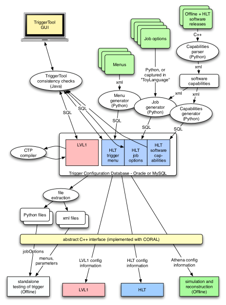
The trigger configuration system consists of a central relational database (TriggerDB) that stores the configuration data, tools to populate the database and ensure its consistency, and interfaces to extract the stored data in preparation for data taking or other purposes (e.g. simulation, data analysis, etc.). A schematic overview of the configuration system is given in Fig. 2.
2.1 Trigger database
The TriggerDB is the central part of the configuration system. It is used to store and protect all data that are needed to configure the three levels of the ATLAS trigger: the LVL1 trigger menu, the HLT trigger menu, the parameters (job options) of all software (SW) packages running in the HLT, and the corresponding release information. Using the relational structure of the database, the various single data elements (e.g. hardware registers of LVL1, algorithm parameters of HLT selection algorithms or environment variables) are grouped together to form bigger entities in a hierarchical tree-like structure. Each element in the database is identified by a unique integer key. These keys are used to construct larger entities higher up in the hierarchy. The top-level entities, i.e. the ones containing all information needed to configure all three trigger levels are called configurations. A configuration is composed of one LVL1 configuration and one HLT configuration, which in turn consist of other components like trigger menus and prescale sets eventually leading to the basic configuration parameters111 As indicated in Fig. 2 the HLT configuration can also be regarded as being composed of the HLT menu, the algorithm parameters (HLT job options) and the HLT software capabilities. The latter is used to enforce consistency between the algorithms used in the configuration and the capabilities of a SW release. . For the purpose of human readability all data entities are given a string name and a version number. The tree-like structure described above allows one to reuse parts of a configuration when creating a new configuration, by simply changing the referencing foreign keys in entities higher in the hierarchy, thereby avoiding unnecessary data duplication.
It is foreseen to store in the TriggerDB all versions of configurations that have been used for data taking and those prepared for simulation and test runs. The unique integer key (the Master Key) that identifies a certain configuration will be transfered to the conditions database of the experiment [4]. This Master Key provides the unique reference to a configuration and can therefore be used to retrieve the configuration at a later stage.
The TriggerDB is located on the same server as the conditions database without, however, being embedded into its schema. Making use of the infrastructure provided by ATLAS and CERN-IT, the TriggerDB will follow all replication steps of the conditions database and will be available at CERN and at external sites. The TriggerDB and all related tools are implemented to run on both MySQL and ORACLE.
It should be emphasised that the consistency of the configuration data is an essential requirement that the configuration system must fulfil. Inconsistent trigger configurations can lead to data loss or data unusable for physics analysis. Wherever possible, the relational schema has been designed to enforce consistency. Moreover, the database population tools scrutinise the consistency of the data they upload.
2.2 Population Tools
Due to the complexity of the trigger system and its configuration, the population of the database, including the composition of the trigger menus, needs dedicated tools. At present two complementary systems are under development (see Fig. 2):
-
1.
The TriggerTool is a stand-alone, java-based graphical user interface to the TriggerDB.
-
2.
Custom python scripts convert the xml- and python-based HLT menu and job configuration into SQL statements that populate the database. The reverse mode where xml and job configuration files are created from the database is also possible (see next Section).
The TriggerTool is the central database population tool. It foresees shift-crew and expert levels with different access restrictions. Shifters can only choose among a list of approved trigger menus and prescale sets to configure the next run. Experts are allowed to modify existing and add new LVL1 and HLT trigger menus. The TriggerTool handles the proper reordering of the keys between the database tables. An important feature of the TriggerTool is its capacity to perform automatic queries to validate the validity of a trigger configuration. Examples for this are valid collections of thresholds and prescale sets for LVL1, consistent step-wise HLT signatures, and the coherent configurations of the HLT feature extraction (event reconstruction) and selection algorithms, each belonging to a unique software setup. The TriggerTool also provides a convenient lightweight database browser for offline users, providing advanced search functionality and access from remote locations.
As indicated in Fig. 2, the python scripts are used to populate the HLT database tables. This includes the default configuration properties of the HLT algorithms (for example feature extraction options and selection requirements), and the dynamic link libraries, services and tools required by the algorithms. These components must be linked to the corresponding software release setups, which requires that all the capabilities of the releases involved are filled into the database (the capability of a release defines the available features of the trigger software). The database population is only feasible by means of automatic release scanning tools, currently implemented as python parsers. The extracted information is written to xml files, before being converted to SQL statements and uploaded to the database. It is foreseen to perform such a scan for each new release, identifying the changes between releases in the process. Specific configuration of the algorithms, which goes beyond the default release settings, must be inserted by hand into the database using the TriggerTool.
Another ingredient needed is a compiler to translate the human-readable LVL1 menu into the input files used to program the look-up tables (LUT) and content addressable memory (CAM) that contain the selection logic as part of the central trigger processor (CTP) of the first level trigger. The compiler is implemented in C++ and can run in stand-alone mode taking the xml files extracted from the TriggerDB (see below). In addition, the compiler is integrated into the TriggerTool reading the LVL1 menu from the TriggerDB. The output LUT and CAM files for each LVL1 menu are then stored in the TriggerDB and made available for online running.
2.3 Data retrieval from the TriggerDB
There is a variety of use cases for data retrieval from the TriggerDB, but the configuration of the complete system at the start of an online data-taking run and the configuration of the offline simulation are arguably the most challenging. Two independent data paths from the TriggerDB are foreseen and have been implemented (cf. Fig. 2):
-
1.
Configuration sets can be extracted from the TriggerDB into intermediate files (xml or python). These files can then be used by the user for stand-alone tests for, e.g., development of new configurations and for tests of the online trigger system without interference with the TriggerDB during the commissioning of the system.
-
2.
Configuration sets can be accessed by direct access to the TriggerDB. The various clients (e.g. LVL1 hardware modules or HLT processing nodes) contact the TriggerDB directly to get their configuration objects.
To keep the differences between configuring via intermediate files and via direct database access at a minimum, both configuration paths make use of a common abstract interface. This interface is implemented in C++ and is foreseen to be used online for data taking as well as for the various offline use cases. Its two implementations are based on the Xerces xml parser and the CORAL [5] package allowing a vendor-independent access to the TriggerDB.
3 DEPLOYMENT AND FIRST TESTS
Tests of the LVL1 configuration system have been performed with the offline simulation, yielding promising results. The two paths (via xml or direct database access) can be routinely used to configure the simulation of the LVL1 trigger. To complete the configuration system the C++ abstract interfaces need to be integrated with the online state-machines controlling the various parts of the LVL1 system in data-taking mode. As the number of clients in the LVL1 online system is relatively small (about 20 CPUs controlling the hardware crates of LVL1 and running the online state-machines) performance problems are not expected for LVL1.
An initial test was performed of configuring the HLT from the TriggerDB using a LVL2 muon selection chain. The complete configuration of the muon chain together with the necessary auxiliary services and tools were described in the TriggerDB. The muon selection chain was run on a multi node system containing six LVL2 processing units, a LVL2 supervisor and a read-out system (ROS) emulator222See [2] for a detailed description of the HLT components.. Events were pre-loaded to the ROS emulator and retrieved by the processing units. Every LVL2 processing unit retrieved the configuration from the TriggerDB. In a python module, the retrieved information was converted in memory to standard python configuration statements used for the ATLAS software framework Athena, which were then used to set up all necessary Athena modules. In this very early version it took about one second to retrieve all configuration information from a single MySQL server. For the final system it is envisaged to provide all necessary information in the TriggerDB as a database view, which will then be read directly by a service setting up the necessary software environment. This service is presently under development.
Next steps in the development of the configuration system are the integration of the system with the LVL1 hardware and the setup of more complicated configurations for the HLT including more than one selection chain. Performance studies and tuning will be an important issue for the configuration of the large HLT processor farms in the context of the online database architecture of the ATLAS experiment.
References
- [1] The ATLAS Collaboration, “ATLAS, First-Level Trigger - Technical Design Report”, CERN, Geneva, Switzerland, CERN-LHCC-98-14, 1998; for more recent results see: The ATLAS TDAQ LVL1 group, “The first-level trigger of ATLAS”, to appear in the proceedings of the HEPP-EPS2005 conference, Lisbon, arXiv:physics/0512195 and references therein.
- [2] The ATLAS Collaboration, “ATLAS, High-Level Trigger Data Acquisition and Controls - Technical Design Report”, CERN, Geneva, Switzerland, CERN-LHCC-2003-022, 2003.
- [3] G. Comune, S. George, J. Haller, P. Morettini, C. Schiavi, R. Stamen, S. Tapprogge, “Steering the ATLAS High Level Trigger“, these proceedings.
- [4] A. Valassi, “COOL, Performance and distribution tests” and “COOL Development and Deployment - Status and Plans“, these proceedings.
- [5] R. Chytracek, G. Govi, D. Duellmann, I. Papadopoulos, Y. Shapiro, Z. Xie, “CORAL, a software system for vendor-neutral access to relational databases”, these proceedings.