Scanning probe microscopy of thermally excited mechanical modes of an optical microcavity
Abstract
The resonant buildup of light within optical microcavities elevates the radiation pressure which mediates coupling of optical modes to the mechanical modes of a microcavity. Above a certain threshold pump power, regenerative mechanical oscillation occurs causing oscillation of certain mechanical eigenmodes. Here, we present a methodology to spatially image the micro-mechanical resonances of a toroid microcavity using a scanning probe technique. The method relies on recording the induced frequency shift of the mechanical eigenmode when in contact with a scanning probe tip. The method is passive in nature and achieves a sensitivity sufficient to spatially resolve the vibrational mode pattern associated with the thermally agitated displacement at room temperature. The recorded mechanical mode patterns are in good qualitative agreement with the theoretical strain fields as obtained by finite element simulations.
pacs:
42.65Yj, 42.55-Sa, 42.65-HwThe work of V.B. BraginskyBraginsky et al. (2001) predicted that due to radiation pressure the mechanical mirror-eigenmodes of a Fabry-Pérot (FP) resonator can couple to the optical modes, leading to a parametric oscillation instability. This phenomenon is characterized by regenerative mechanical oscillation of the mechanical cavity eigen-modes. Significant theoretical studies have been devoted to this effect in the context of the laser gravitational wave observatory (LIGO) (Braginsky et al. (2001); Kells and D’Ambrosio (2002)), as it potentially impedes gravitational wave detection. Whereas in macroscopic resonators the influence of radiation pressure is weak and only appreciable at high power levelsA. Dorsel et al. (1983), the mutual coupling of optical and mechanical modes is significantly enhanced in optical microcavities (such as silica microspheresBraginsky et al. (1989), microdisks or toroidsArmani, D.K. and Kippenberg, T.J. and Spillane, S.M. and Vahala, K.J. (2003)) which simultaneously exhibit ultra-high-Q optical modes and high-Q mechanical modes in the radio-frequency range. The combination of high optical power and small mechanical mass and dissipation leads to threshold levels in the micro-Watt regime for regenerative acoustic oscillations (i.e. parametric oscillation instability), making it the dominant micro-cavity nonlinear optical effect as reported previously in toroid microcavitiesKippenberg, T.J. and Spillane, S.M. and Vahala, K.J. (2005); Rokhsari, H. and Kippenberg, T.J. and Carmon, T. and Vahala, K.J. (2005); Carmon et al. (2005).
In this letter, we report a novel scanning-probe technique, which allows direct spatial imaging of the amplitude of the micro-mechanical modes of a microcavity associated with their thermally driven displacement at room temperature. The method is based on the induced resonance shift by a scanning probe tip, whose influence on the mechanical oscillator’s resonance frequency is detected optically via the light transmitted past the microcavity. This technique is passive in nature, and reaches a sensitivity which is sufficient to detect the minute amplitude of the thermally driven mechanical modes. Initial demonstrations of this method show very good agreement between the mechanical mode distribution obtained by scanning-probe spectroscopy and finite-element modeling. Besides providing insight into the spatial pattern of the mechanical modes of an optical microcavity, this technique should provide a useful tool for the study of other micromechanical or nano-mechanical resonatorsZalalutdinov et al. (2000).
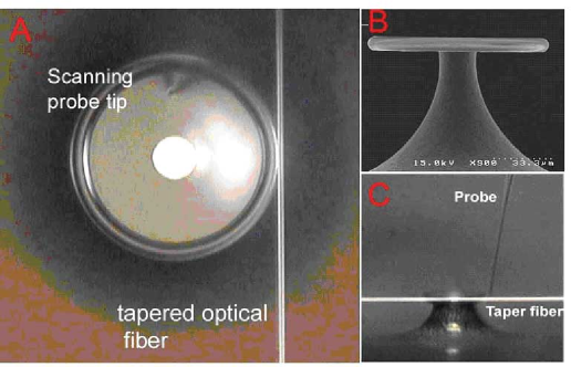
The experimental scenario is depicted schematically in Figure 1. It consists of a standard geometry in which a pump wave is coupled from a waveguide (a tapered optical fiberCai et al. (2000)) to an ultra-high-Q microcavity mode of a toroid microcavity on a chip Armani, D.K. and Kippenberg, T.J. and Spillane, S.M. and Vahala, K.J. (2003). In addition to their excellent optical properties, this microcavity geometry - owing to its free hanging silica membrane supporting the toroidal periphery - possesses high-Q micromechanical resonances. The inset in figure 3 shows the first two () mechanical modes of the structure, calculated using finite element modeling. The modes are rotationally symmetric (i.e. their azimuthal mode number being ). As evident from the finite element simulation, the motion of the first and second order flexural mode is primarily in the out-of plane direction (of the toroid and disk).
On resonance the high buildup of light within the cavity leads to an increase in radiation pressure, expanding the cavity (optical round trip) and thereby coupling the optical mode to the mechanical eigenmodes of the cavity as described in RefsKippenberg, T.J. and Spillane, S.M. and Vahala, K.J. (2005); Rokhsari, H. and Kippenberg, T.J. and Carmon, T. and Vahala, K.J. (2005); Carmon et al. (2005). The mutual coupling of the mechanical and optical mode is described by the following set of equations:
| (1) |
| (2) |
The first equation describes the mechanical eigenmode, where is the mechanical frequency, is normalized to mechanical energy i.e. , which decays with the lifetime (i.e. ). Correspondingly is the energy in the optical whispering gallery mode ( is the power, where is the cavity round-trip time), which is excited with a pump laser detuned by the amount from line-center. The expressions and describe the mutual coupling of optical and mechanical eigen-modes, and depend on the respective modes. The coupling can be mapped to a Fabry-Pérot cavity, by considering the modes as a harmonic oscillator with in plane (radial amplitude , which modulates the cavity pathlength) and out-of plane motion (amplitude ). Solving equations (1)-(2) shows that the radiation pressure causes the mechanical oscillator to experience: (1) a change in rigidity; (2) the addition of a velocity dependent term (providing either a viscous force or an accelerating force), i.e.
| (3) |
The approximate solutions are (for ): and Consequently, the laser being detuned to the blue with respect to the cavity resonance () leads to mechanical gain. If the mechanical gain exceeds the mechanical loss, a parametric oscillation instability can be observed in which regenerative mechanical oscillations occur. This phenomenon has been observed for the first time recently in toroid microcavities and has been extensively characterizedKippenberg, T.J. and Spillane, S.M. and Vahala, K.J. (2005); Rokhsari, H. and Kippenberg, T.J. and Carmon, T. and Vahala, K.J. (2005); Carmon et al. (2005).
Here we investigate the interaction of a local probe (whose dimensions are small compared to the optical microcavity) with the mechanical modes, and demonstrate a novel method which can spatially resolve the mechanical mode pattern associated with the thermally agitated displacement of the toroid microcavities. In order to spatially image the mechanical modes a scanning probe is introduced as shown in Figure 1 which contacts the free hanging disk connected to the toroidal cavity and supported by the silicon pillar. The scanning probe setup consisted of a silica tapered fiber tip controlled by a piezoelectric stage (with 80 nm resolution). The tip of the scanning probe was fabricated by laser melting and stretching of a single mode fiber, and had a tip-diameter ca. 3 . The probe was lowered onto the silica support disk (i.e. the interior region of the toroidal microcavity), while the taper was simultaneously coupled to the toroid. Figure 1 a,c shows an optical micrograph of the taper-cavity system in contact with the probe (top view, side view respectively). The presence of the probe couples the mechanical microcavity mode to the acoustical modes of the probe. This coupling has two effects; (1) the mechanical quality () factor of the microcavity structure is reduced; and (2) the mechanical eigenfrequency () is changed, due to a change in rigidityZalalutdinov et al. (2000). We note the similarity of this method to the ”AC” mode of an atomic force microscopeBinnig et al. (1986); Albrecht et al. (1990) , which uses the change in mechanical frequency of an oscillating cantilever to record the topology of the surface (induced by position dependent forces due to the presence of near-field forces). However, in the present case, not the resonant frequency shift of the probe is monitored, but rather the resonant frequency and of the micromechanical resonator itself. As the mechanical cavity-motion modulates the optical power coupled to the cavity (i.e., cavity transmission) and thereby creates sidebands at in the transmitted optical spectrum, the mechanical oscillation frequency and Q-factor can be readily measured via the transmitted pump power past the cavity.
If the optical pump power is low (compared to the threshold for mechanical oscillations to occur) then the optical field acts purely as a probe of the mechanical oscillation and does not modify the mechanical properties of the structure (i.e. the light will not excite mechanical resonances, since equivalent to ). The threshold for mechanical oscillation can be increased rapidly (and the regime achieved), when biasing the coupling junction into the overcoupled regimeSpillane, S.M. and Kippenberg, T.J. and Painter, O.J. and Vahala, K.J. (2003), owing to the fact that threshold scales inverse cubically with the optical factor (in cases where the mechanical frequency is smaller than the cavity bandwidthKippenberg, T.J. and Spillane, S.M. and Vahala, K.J. (2005); Rokhsari, H. and Kippenberg, T.J. and Carmon, T. and Vahala, K.J. (2005)). Therefore the system can be described by a simplified set of equations by introducing and (which contain the radiation pressure induced shift in resonance and change in rigidity):
| (4) |
In this regime (), the oscillator is only thermally driven (i.e. the energy being equal to ), causing modulation of the field stored inside the cavity, due to the change in cavity path-length. The solutions in this regime to the above equation are given by:
| (5) |
The appearance of sidebands (at and harmonics) is thus observable at the mechanical eigen-frequencies with a modulation depth which is governed by the specifics of the coupling mechanism and the amplitude of the motion, i.e. , where is the thermal displacement noise, as given by . The temperature in the presence of the optical probe field is increased above the ambient temperature of 300 K by several degrees, due to absorption of photons and subsequent heating (as evidenced from thermal hysteresis)Rokhsari et al. . Detection of light transmitted past the microcavity exhibits modulation components at and harmonics, as the transmitted light past the tapered fiber interferes with the modulated field emerging from the cavity, i.e.
| (6) |
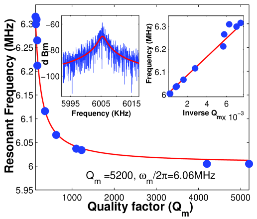
The transmission is given by and maximum modulation depth occurs at critical coupling and for detuning of , where the slope of the Lorentzian transmission is maximum. By spectral decomposition of the cavity transmission (), the mechanical resonance frequency and mechanical Q-factor can therefore be recorded. The inset of Figure 2 shows the lorentzian lineshape of the first flexural mode as well as a theoretical fit (solid line). Therefore, the transmitted pump light can be used to optically probe both the micromechanical resonant frequency, as well as the mechanical Q factor.
Having established a detection technique for the mechanical resonant characteristics (, ) static probe contact measurements were carried out. When the probe is brought in contact with the silica disk, a reduction of the mechanical Q factor is observed, as the probe constitutes a dissipative loss channel to the mechanical oscillator. The reduction of Q factor increases with contact pressure of the probe. In addition, we note that the observed decrease in is concomitant with an increase in mechanical eigenfrequency. Figure 2 shows as a function of frequency . As can be seen, a linear relationship between mechanical loss () and induced frequency shift () is obtained. This is non-intuitive at first sight, and not in agreement with a damped harmonic oscillator model, which predicts that the increase in damping (e.g. due to the tip) causes a red-shift of the resonance frequency, i.e. . However, the presence of the tip causes not only a change in dissipation but also a change in the rigidity of the oscillator () which causes a blue-shift by . This effect is well known for cantilevers used for atomic force microscopy Binnig et al. (1986); Albrecht et al. (1990); Zalalutdinov et al. (2003). This empirical linear relationship of and was recorded for different modes (1,2,3) and found repeatedly for all measurements reported in this letter.
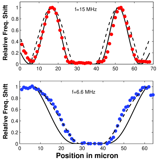
Next spatial probing was carried out, and the influence of the mechanical resonant characteristics (, ) on the spatial probe position analyzed. Figure 3 shows the results of this measurement in which scanning is performed along the entire cross section of a toroidal cavity with a diameter of 104 (the resonant frequencies for the and modes were 6.07 MHz and 14.97 MHz). The cavity was fabricated with a strong undercut, in order to promote the recorded amplitudes (the thermal displacement was approximately pm for the mode). As can be observed in Fig. 3 (upper graph) for the mode (which in its unperturbed state has a resonant frequency of 6.07 MHz) a continuous decrease, followed by a plateau and then followed by an increase in the mechanical frequencies was observed while scanning from the one outer edge of the toroid to the opposing edge (The frequency range covered the unperturbed value of 6.07 MHz to 6.17 MHz, equating to a fractional change of ). Similarly the mechanical Q-factor was continually reduced, plateaud in the interior region, followed again by an increase. The data in Fig. 3 represents the recorded frequency shift normalized to unity. This is a first indication, that the induced frequency shifts and Q-factor change depend critically on the amplitude of the mechanical oscillations, and therefore probe local information about the mechanical amplitude. To confirm that this effect is not topological in nature (e.g. due to an irregular shape of the interior silica disk surface), and in order to establish that the recorded shift in frequency is indeed a measure of the mechanical amplitude, thedependencies for the mode were measured. The result for the mode is shown in Fig. 3b, and is clearly distinct from the mode. These measurements were obtained repeatedly on different samples, with different tips. As evident the mechanical frequency is perturbed maximally at the point of maximum mechanical amplitude and decreases to zero in the interior of the toroid, as well as at the outer edge. This clearly indicates that the observed frequency shift is not related to the surface-topology, but in fact provides direct information on the local mechanical oscillation amplitude. In order to make a qualitative comparison of the recorded frequency shift and the actual mechanical motion, the numerically calculated amplitude ( in the z-direction) is superimposed in figure 3. The calculations employed finite element modeling of the actual geometry (as inferred by SEM). The theoretically modeled amplitudes were scaled to unity in the vertical direction. We note that the position of maximum amplitude of the and mode, agrees very well with the finite element simulation as does the overall shape of the curves.While a detailed understanding of how the probe changes the resonant characteristics of the oscillator is at present lacking, the data along with the modeling strongly suggests that the recorded frequency shifts do directly relate to the strain fields in the z-direction. Note that deviation of the recorded shift with the numerical modeling is expected, due to the convolution of the finite probe size (in the experiments this is approximately 3 ) with the mechanical motion.
In summary a novel method is presented which allows direct probing of the vibrational mode patterns of a micromechanical oscillator. The method relies on spatially recording the induced frequency shift by a scanning probe tip, and exhibits sufficient sensitivity to detect the mode pattern of thermally excited acoustic modes. The present results should also be applicable to other types of micromechanical oscillators, and could provide a useful tool in the field of MEMS/NEMSZalalutdinov et al. (2000), as well as to achieve tuning of mechanical resonator modesZalalutdinov et al. (2000),.
Acknowledgements.
This research was supported by the DARPA and the Caltech Lee Center for Advanced Networking. TJK gratefully acknowledges receipt of a postdoctoral fellowship from the IST-CPI.References
- Braginsky et al. (2001) V. B. Braginsky, S. E. Strigin, and S. P. Vyatchanin, Physics Letters A 287, 331 (2001).
- Kells and D’Ambrosio (2002) W. Kells and E. D’Ambrosio, Physics Letters A 229, 326 (2002).
- A. Dorsel et al. (1983) A. Dorsel et al., Physical Review Letters 51, 1550 (1983).
- Braginsky et al. (1989) V. Braginsky, M. Gorodetsky, and V. Ilchenko, Physics Letters A 137, 393 (1989).
- Armani, D.K. and Kippenberg, T.J. and Spillane, S.M. and Vahala, K.J. (2003) Armani, D.K. and Kippenberg, T.J. and Spillane, S.M. and Vahala, K.J. , Nature 421, 925 (2003).
- Kippenberg, T.J. and Spillane, S.M. and Vahala, K.J. (2005) Kippenberg, T.J. and Spillane, S.M. and Vahala, K.J., Physical Review Letters 95, 033901 (2005).
- Rokhsari, H. and Kippenberg, T.J. and Carmon, T. and Vahala, K.J. (2005) Rokhsari, H. and Kippenberg, T.J. and Carmon, T. and Vahala, K.J., Optics Express 13, 5293 (2005).
- Carmon et al. (2005) T. Carmon, H. Rokhsari, L. Yang, T. Kippenberg, and K. Vahala, Physical Review Letters 94, 223902 (2005).
- Zalalutdinov et al. (2000) M. Zalalutdinov, B. D. Illic, Czaplewski, A. Zehnder, H. Craighead, and J. Parpia, Applied Physics Letters 77, 3278 (2000).
- Cai et al. (2000) M. Cai, O. Painter, and K. Vahala, Physical Review Letters 85, 74 (2000).
- Binnig et al. (1986) G. Binnig, C. Quate, and C. Gerber, Physical Review Letters 56, 930 (1986).
- Albrecht et al. (1990) T. Albrecht, P. Gr tter, D. Horne, and D. Rugar, Journal of Applied Physics 69, 668 (1990).
- Spillane, S.M. and Kippenberg, T.J. and Painter, O.J. and Vahala, K.J. (2003) Spillane, S.M. and Kippenberg, T.J. and Painter, O.J. and Vahala, K.J., Physical Review Letters 91, art. no. (2003).
- (14) H. Rokhsari, S. Spillane, and K. Vahala, Applied Physics Letters (????).
- Zalalutdinov et al. (2003) M. Zalalutdinov, K. Aubin, M. Pandey, A. Zehnder, R. Rand, H. Craighead, J. Parpia, and B. Houston, Applied Physics Letters 83, 3281 (2003).