Optical Conformal Mapping and Dielectric Invisibility Devices
Abstract
An invisibility device should guide light around an object as if nothing were there, regardless where the light comes from. Ideal invisibility devices are impossible due to the wave nature of light. This paper develops a general recipe for the design of media that create perfect invisibility within the accuracy of geometrical optics. Here the imperfections of invisibility can be made arbitrarily small to hide objects that are much larger than the wavelength. Using modern metamaterials, practical demonstrations of such devices seem possible. The method developed here can be also applied to escape from detection by other forms of waves such as sound.
pacs:
42.15.-i, 02.40.TtAccording to Fermat’s Principle BornWolf , light rays take the shortest optical paths in dielectric media. Here the refractive index integrated along the ray trajectory defines the path length. When is spatially varying the shortest optical paths are not straight lines, but are curved, in general. This light bending is the cause of many optical illusions. For example, in a mirage in the desert Feynman , light rays from the sky are bent above the hot sand where the air is thin and the refractive index is low, because in this way the rays minimize their optical paths, creating images of the sky that deceive the observer as illusions of water Feynman . Imagine a different situation where a medium guides light around a hole in it. Suppose that all parallel bundles of incident rays are bent around the hole and recombined in precisely the same direction as they entered the medium. An observer would not see the difference between light passing through the medium or propagating across empty space (or, equivalently, in a uniform medium). Any object placed in the hole would be hidden from sight. The medium would create the ultimate optical illusion: invisibility Gbur .
However, Nachman Nachman and Wolf and Habashy WolfHabashy proved that perfect invisibility is unachievable, except in a finite set of discrete directions where the object appears to be squashed to infinite thinness and for certain objects that are small compared with the wavelength Kerker . In order to carry images, though, light should propagate with a continuous range of spatial Fourier components, i.e. in a range of directions. The mathematical reason for the impossibility of perfect invisibility is the uniqueness of the inverse-scattering problem for waves Nachman : the scattering data, i.e. the directions and amplitudes of the transmitted plane-wave components determine the spatial profile of the refractive index Nachman . Therefore, the scattering data of light in empty space are only consistent with the propagation through empty space. Perfect illusions are impossible due to the wave nature of light.
On the other hand, Nachman’s theorem Nachman does not limit the imperfections of invisibility, they may be very small, nor does the theorem apply to light rays, i.e. to light propagation within the regime of geometrical optics BornWolf . Here we develop a general recipe, accompanied by an example, for the design of media that create perfect invisibility for light rays over a continuous range of directions. Since this method is based on geometrical optics BornWolf , the inevitable imperfections of invisibility can be made exponentially small for objects that are much larger than the wavelength of light.
To manufacture a dielectric invisibility device, media are needed that possess a wide range of the refractive index in the spectral domain where the device should operate. In particular, Fermat’s Principle BornWolf seems to imply that in some spatial regions, because only in this case the shortest optical paths may go around the object without causing phase distortions. In our example, varies from to about . In practice, one could probably accept a certain degree of visibility that significantly reduces the demands on the range of the refractive index.
Extreme values of occur when the material is close to resonance with the electromagnetic field. Metamaterials Smith with man-made resonances can be manufactured using appropriately designed circuit boards, similar to the ones used for demonstrating negative refraction Shelby . In this research area, the quest for the perfect lens Pendry has lead to spectacular recent improvements Smith ; Recent ; Grigorenko mainly focused on the magnetic susceptibilities so far. In such metamaterials, each individual circuit plays the role of an artificial atom with tunable resonances. With these artificial dielectrics, invisibility could be reached for frequencies in the microwave to terahertz range. In contrast, stealth technology is designed to make objects of military interest as black as possible to radar. There, using impedance matching Jackson , electromagnetic waves are absorbed without reflection, i.e. without any echo detectable by radar. Recently, nanofabricated metamaterials with custom-made plasmon resonances have been demonstrated Grigorenko that operate in the visible range of the spectrum and may be modified to reach invisibility here.
Our method is also applicable to other forms of wave propagation, for example to sound waves, where the index describes the ratio of the local phase velocity of the wave to the bulk value, or to quantum-mechanical matter waves where external potentials act like refractive-index profiles BornWolf . For instance, one could use the profiles of described here to protect an enclosed space from any form of sonic tomography. But, for having a definite example in mind, we focus on light in media throughout this paper. We study the simplest non-trivial case of invisibility, an effectively two-dimensional problem.
Consider a dielectric medium that is uniform in one direction and light of wavenumber that propagates orthogonal to that direction. The medium is characterized by the refractive-index profile . In order to satisfy the validity condition of geometrical optics, must not significantly vary over the scale of an optical wavelength BornWolf . To describe the spatial coordinates in the propagation plane we use complex numbers with the partial derivatives and where the star symbolizes complex conjugation. In the case of a gradually varying refractive-index profile both amplitudes of the two polarizations of light obey the Helmholtz equation BornWolf
| (1) |
written here in complex notation with the Laplace operator . Suppose we introduce new coordinates described by an analytic function that does not depend on . Such functions define conformal maps Nehari that preserve the angles between the coordinate lines. Since , we obtain in space a Helmholtz equation with the transformed refractive-index profile that is related to the original one as
| (2) |
Suppose that the medium is designed such that is the modulus of an analytic function . The integral of defines a map to new coordinates where, according to Eq. (2), the transformed index is unity. Consequently, in coordinates the wave propagation is indistinguishable from empty space where light rays propagate along straight lines. The medium performs an optical conformal mapping to empty space. If approaches for all incident waves appear at infinity as if they have travelled through empty space, regardless what has happened in the medium. However, as a consequence of the Riemann Mapping Theorem Nehari nontrivial coordinates occupy Riemann sheets with several , one on each sheet. Consider, for example, the simple map
| (3) |
illustrated in Fig. 1, that is realized by the refractive-index profile .
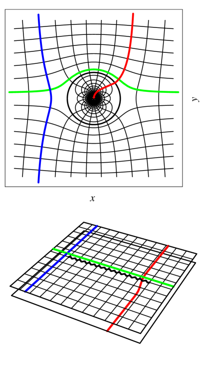
The constant characterizes the spatial extension of the medium. The function (3) maps the exterior of a circle of radius on the plane onto one Riemann sheet and the interior onto another. Light rays traveling on the exterior sheet may have the misfortune of passing the branch cut between the two branch points . In continuing their propagation, the rays approach on the interior sheet. Seen on the physical -plane, they cross the circle of radius and approach the singularity of the refractive index at the origin. For general , only one on the Riemann structure in space corresponds to the true of physical space and the others to singularities of . Instead of traversing space, light rays may cross the branch cut to another Riemann sheet where they approach . Seen in physical space, the rays are irresistibly attracted towards some singularities of the refractive index. Instead of becoming invisible, the medium casts a shadow that is as wide as the apparent size of the branch cut is. Nevertheless, the optics on Riemann sheets turns out to serve as a powerful theoretical tool for developing the design of dielectric invisibility devices.
All we need to achieve is to guide light back from the interior to the exterior sheet, i.e., seen in physical space, from the exterior to the interior layer of the device. To find the required refractive-index profile, we interpret the Helmholtz equation in space as the Schrödinger equation BornWolf of a quantum particle of effective mass moving in the potential with energy such that BornWolf . We wish to send all rays that have passed through the branch cut onto the interior sheet back to the cut at precisely the same location and in the same direction they entered. This implies that we need a potential for which all trajectories are closed. Assuming radial symmetry for around one branch point , say in our example, only two potentials have this property, the harmonic oscillator and the Kepler potential LL1 . In both cases the trajectories are ellipses LL1 that are related to each other by a transmutation of force according to the Arnol’d-Kasner theorem ArnoldKasner . The harmonic oscillator corresponds to the transformed refractive-index profile with
| (4) |
where is a constant radius. The Kepler potential with negative energy is realized by the profile with
| (5) |
Note that the singularity of the Kepler profile in space is compensated by the zero of at a branch point in physical space such that the total refractive index (2) is never singular. In both cases (4) and (5), defines the radius of the circle on the interior sheet beyond which would be negative and hence inaccessible to light propagation. This circle should be large enough to cover the branch cut. The inverse map turns the outside of the circle into the inside of a region bounded by the image of the circle line in space. No light can enter this region. Everything inside is invisible.
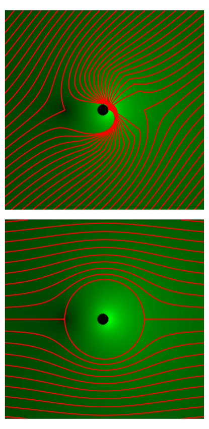
Yet there is one more complication: light is refracted BornWolf at the boundary between the exterior and the interior layer. Seen in space, light rays encounter here a transition from the refractive index to . Fortunately, refraction is reversible. After the cycles on the interior sheets light rays are refracted back to their original directions, as illustrated in Fig. 2.

The invisibility is not affected, unless the rays are totally reflected. According to Snell’s Law BornWolf , discovered by Ibn Sahl more than a millennium ago Rashed , rays with angles of incidence with respect to the branch cut enter the lower sheet with angles such that . If this equation may not have real solutions for larger than a critical angle . Instead of entering the interior layer of the device the light is totally reflected BornWolf . The angle defines the acceptance angle of the dielectric invisibility device, because beyond the device appears silvery instead of invisible. The transformed refractive-index profiles (4) and (5) at the boundary between the layers are lowest at the other branch point that limits the branch cut, in our example. In the case of the harmonic-oscillator profile (4) lies always below and we obtain the acceptance angle
| (6) |
For all-round invisibility, the radius should approach infinity, which implies that the entire interior sheet is employed for guiding the light back to the exterior layer. Fortunately, the Kepler profile (5) does not lead to total reflection if . In this case, the invisible area is largest for
| (7) |
Figure 3 illustrates the light propagation in a dielectric invisibility device based on the simple map (3) and the Kepler profile (5) with . Here ranges from to about , but this example is probably not the optimal choice. One can chose from infinitely many conformal maps that possess the required properties for achieving invisibility: for and two branch points and . The invisible region may be deformed to any simply-connected domain by a conformal map that is the numerical solution of a Riemann-Hilbert problem Ablowitz . We can also relax the tacit assumption that connects the exterior to only one interior sheet, but to sheets where light rays return after cycles. If we construct as with some analytic function of the required properties and a constant length scale the refractive-index profile is identical for all scales . Finding the most practical design is an engineering problem that depends on practical demands. This problem may also inspire further mathematical research on conformal maps, in order to find the optimal design and to extend our approach to three dimensions.
Finally, we return to the starting point and ask why our scheme does not violate Nachman’s theorem Nachman that perfect invisibility is unattainable. The answer is that waves are not only refracted at the boundary between the exterior and the interior layer, but also reflected, and that the device causes a time delay. However, the reflection can be significantly reduced by making the transition between the layers gradual over a length scale much larger than the wavelength or by using anti-reflection coatings. In this way the imperfections of invisibility can be made as small as the accuracy limit of geometrical optics BornWolf , i.e. exponentially small. One can never completely hide from waves, but from rays.
I am grateful to Leda Boussiakou, Luciana Davila-Romero, Mark Dennis, Malcolm Dunn, Greg Gbur, Clare Gibson, Julian Henn and Awatif Hindi for the discussions that led to this paper. My work has been supported by the Leverhulme Trust and the Engineering and Physical Sciences Research Council.
References
- (1) M. Born and E. Wolf, Principles of Optics (Cambridge University Press, Cambridge, 1999).
- (2) R. P. Feynman, R. B. Leighton, and M. Sands, The Feynman lectures on physics. Mainly mechanics, radiation and heat. Chapter 26 (Addison Wesley, Reading, Mass., 1983).
- (3) G. Gbur, Prog. Opt. 45, 273 (2003).
- (4) A. I. Nachman, Ann. Math. 128, 531 (1988).
- (5) E. Wolf and T. Habashy, J. Mod. Opt. 40, 785 (1993).
- (6) M. Kerker, J. Opt. Soc. Am. 65, 376 (1975); A. Alu and N. Engheta, Phys. Rev. E 72, 016623 (2005).
- (7) D. R. Smith, J. B. Pendry, and M. C. K. Wiltshire, Science 305, 788 (2004).
- (8) R. A. Shelby, D. R. Smith, and S. Schultz, Science 292, 77 (2001).
- (9) J. B. Pendry, Phys. Rev. Lett. 85, 3966 (2000).
- (10) A. Grbic and G. V. Eleftheriades, Phys. Rev. Lett. 92, 117403 (2004); T. J. Yen et al., Science 303, 1494 (2004); S. Linden et al., ibid. 306, 1351 (2004).
- (11) A. N. Grigorenko et al., Nature 438, 335 (2005).
- (12) J. D. Jackson, Classical Electrodynamics (Wiley, New York, 1998).
- (13) Z. Nehari, Conformal Mapping (McGraw-Hill, New York, 1952).
- (14) L. D. Landau and E. M. Lifshitz, Mechanics (Pergamon, Oxford, 1976).
- (15) V. I. Arnol’d, Huygens & Barrow, Newton & Hooke (Birkhäuser Verlag, Basel, 1990); T. Needham, Amer. Math. Monthly 100, 119 (1993); Visual Complex Analysis (Clarendon Press, Oxford, 2002).
- (16) R. Rashed, Isis 81, 464 (1990).
- (17) M. J. Ablowitz and A. S. Fokas, Complex Variables (Cambridge University Press, Cambridge, 1997).