Compact in-place gate valve for molecular beam experiments
Abstract
A high vacuum gate valve for skimmed molecular beam experiments is described.
It is designed with a very short extent of only 10 mm along the molecular
beam axis to minimize the distance between the molecular beam source and the
experiment to provide the maximum molecular flux to the experiment. At the
same time it provides free space on both sides of the skimmer to not disturb
the supersonic expansion in front of the skimmer, to give optical access to
the full distance between beam source and skimmer, and to allow for placing
electrostatic devices very close behind the skimmer. The gate valve allows to
maintain high vacuum conditions ( mbar) in the experimental chamber
while the source chamber is brought up to atmospheric pressure for
modifications or maintenance. The valve can be operated from outside the
vacuum chamber while maintaining vacuum conditions in all chambers.
Copyright 2006 American Institute of Physics. This article may be downloaded
for personal use only. Any other use requires prior permission of the author
and the American Institute of Physics. The following article appeared in
Rev. Sci. Instrum. 77, 016106 (2006) and may be found at
http://dx.doi.org/10.1063/1.2162456.
pacs:
39.10.+j, 07.30.KfMolecular beams are an indispensable tool in physical chemistry and molecular physics. They provide extreme cooling from ambient or elevated temperatures down to 1 K and are used for a large variety of experiments Scoles (1988, 1992). In most applications the molecular beam is skimmed a few cm downstream from the nozzle to reduce the gas-load in the experimental chamber and to select only the most intense part of the beam, or to collimate the beam for reducing the transverse velocity spread.
Small molecules embedded in a supersonic beam can be focused and state-selected using electrostatic lenses Reuss (1988) and they can be decelerated using switched electric fields as in a Stark decelerator Bethlem and Meijer (2003). In such experiments it is desirable to accept the largest attainable fraction of the skimmed beam. This requires, besides other design criteria, to place the device as close to the skimmer as possible, as the particle flux falls off rapidly with distance. At the same time such devices are operated at high electric fields and must be high-voltage conditioned whenever they have been exposed to air. Therefore, it is highly desirable to allow for a vacuum separation of the electrostatic device and the beam source, where changes to the nozzle for different experiments or regular maintenance might be required. Commercial gate valves, however, cannot be used since they take up too much space.

In this note we present an extremely thin gate valve design with an extent along the molecular beam axis of only 10 mm. It allows to keep the experimental chambers under high vacuum () while the source chamber is vented to atmospheric conditions. The valve is implemented in the source chamber of a new Alternate Gradient decelerator experiment for the deceleration of large (bio-)molecules. This experiment needs different complex molecular beam sources to transfer the molecules to be studied into the gas phase, for example a laser desorption setup. These sources require regular maintenance, as well as optical access to the whole distance between nozzle and skimmer. Furthermore, it is important to provide free space around the skimmer in order to not disturb the supersonic expansion. At the same time it is desirable to minimize the distance from the molecular beam source to the decelerator, which is placed directly behind the skimmer.
Low-profile gate valves have been constructed before, but only a few are practicable to isolate skimmed molecular beam sources from high vacuum systems Chaban and Reutt-Robey (1993); Stolow (1996); Marceca et al. (1997). They all have in common that they incorporate the skimmer into the valve. Marceca et al. Marceca et al. (1997) simply close the skimmer opening from the back with a needle, which in our experiment would interfere with the decelerator placed directly behind the skimmer. The design by Stolow Stolow (1996) is a simplified extension of the valve by Chaban et al. Chaban and Reutt-Robey (1993). Both designs are, however, two and a half times thicker than our design and the implementation in a separate conflat flange does not allow for simple optical access directly at the tip of a short skimmer, as is advantageous in our experiments.

In our design, the thin gate valve is integrated into a homebuilt CF 250 flange, that incorporates the gate valve in the wall separating source and deceleration chamber. There are several smaller flanges at right angle to provide optical and mechanical access to the source chamber. The CF 250 flange is welded on a commercial CF 250 four-way cross, that is used as the source chamber of our Alternate Gradient deceleration experiment.
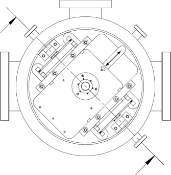
In the explosion drawing of figure 1 the individual parts, which are described in the following, are shown. Figures 2 and 3 show the arrangement of the parts in the assembled gate valve and in figure 3 the height of the valve assembly is depicted. The gate valve is embedded in the CF 250 front flange (8) of the source chamber of our experimental setup. The flange has two CF 100 flanges (10, 15) at right angles at the left and right for optical and mechanical access to the molecular beam source (not shown) and the skimmer (2) from the sides, and a CF 63 (12) flange for access from the top. Integrating these flanges into the CF 250 flange/wall assembly gives optical access to the full distance between the nozzle and the skimmer. We have made use of this to excite CO molecules to their metastable -state and to detect laser induced fluorescence (LIF) signal from metastable CO Jongma et al. (1997) and benzonitrile Borst et al. (2001). The wall separating source and experimental chamber has a central hole of 38 mm diameter. This hole is big enough to not disturb a passing molecular beam and also to provide large enough distances from the high-voltage electrodes in our decelerator. In a groove milled into the wall on the source-side a sledge is mounted to provide the valve closure. The vacuum seal is provided by a diameter Viton O-ring (14) mounted in a circular groove of the wall and pressed between the sledge (16) and the wall. The sledge itself has a circular groove of 44 mm diameter in which the skimmer assembly, consisting of an upper (1) and lower (3) skimmer mount and the skimmer (2) itself, is mounted. The sledge (16) is moved inside the groove by a linear motion feedthrough (Huntington L-2111) mounted on a CF 16 flange (11) into skimming or sealing position. The traveling distance of the sledge between the two positions is 49 mm. In figure 2 the sledge is shown in skimming position. In this position the skimmer position is adjusted onto the molecular beam axis of the experiment. When closing and opening the gate valve the skimmer is reproducibly positioned with a precision of 0.01 mm by two adjustment pins below the sledge moving inside precisely machined slots (7).
When the sledge is positioned it is pressed against the O-ring in the wall by two double rocker arm levers (6, 19) positioned symmetrically around the O-ring. A pair of lever arms is connected by a crossbar at the top to operate two levers simultaneously. Their axes are mounted close to the chamber wall in shaft holders (4, 18) which are fixed on the wall. The levers are operated by two linear motion feedthroughs (Huntington L-2111) mounted on CF 16 flanges (9, 13). The linear motion feedthroughs are protected against angular forces by guides assembled close to the lever arm crossbars (17, front guide not shown in figure 1, see figure 2 for its position). To fix the sledge, the linear motion feedthroughs push against hardened steel plates (5) on the back of the lever arm crossbar. The levers then push the sledge symmetrically against the O-ring with a 15:1 transmission ratio. A pressure difference between the source and deceleration chamber will automatically provide an additional sealing force on the sledge. When there is no large pressure difference between the two sides of the valve (i. e. both chambers at high vacuum or both chambers vented) and the lever arms are released, the sledge can be moved perpendicular to the molecular beam axis by a 50.8 mm linear motion vacuum feedthrough (Huntington L-2111) mounted on a CF 16 flange (11) directly connected to the sledge.
The described gate valve is implemented in a new vacuum system used for the Alternate Gradient deceleration Bethlem et al. (2002) of large molecules. After the original assembly of the chambers we have carefully noted the readings of all linear motion feedthroughs when the sledge is fixed in operation conditions, i. e. when the skimmer is on the beam axis, when the sledge is in sealing position, and while the sledge is moved from one configuration to the other, i. e. when the lever arms are loose. A skimmer (Beam Dynamics, model 1, 1 mm orifice) is mounted on the sledge and carefully aligned onto the molecular beam axis with the sledge fixed in the corresponding position. Then the chambers are evacuated and the decelerator is high-voltage conditioned. When the sledge is moved to sealing position the source chamber can be vented for work on the molecular beam source. Under these conditions the pressure in the deceleration chamber stays at , protecting the multi channel plates from air, and afterward no reconditioning of the high-voltage electrodes is necessary. This process has been performed numerous times over the last year and no recognizable degradation is observed.
The space-effective gate valve presented here is of general use for all molecular beam experiments where the cost of venting the full system is high compared to venting the source-chamber only. This can be due to air-sensitive devices, as high-voltage electrodes, sensitive detectors, or also simply due to vacuum requirements, where venting of the full experiment requires long pumping times due to large volumes or high vacuum requirements in the experimental chambers. The presented gate valve is especially useful for applications that require a short distance between the nozzle and the experimental device, for example hexapole focusing or Stark deceleration of molecular beams. It is invaluable when sources are used that require regular maintenance or cleaning, i. e. laser desorption or ablation sources, discharge sources, pyrolysis sources, or sources that are simply heated or cooled to extreme temperatures.
Acknowledgements.
The authors are grateful to the FHI machine shop for their expert fabrication of the described device.References
- Scoles (1988) G. Scoles, ed., Atomic and molecular beam methods, vol. 1 (Oxford University Press, New York, NY, USA, 1988).
- Scoles (1992) G. Scoles, ed., Atomic and molecular beam methods, vol. 2 (Oxford University Press, New York, NY, USA, 1992).
- Reuss (1988) J. Reuss, State Selection by Nonoptical Methods, chap. 11, pp. 276–292, vol. 1 of Scoles (1988) (1988).
- Bethlem and Meijer (2003) H. L. Bethlem and G. Meijer, Int. Rev. Phys. Chem. 22, 73 (2003), URL http://dx.doi.org/10.1080/0144235021000046422.
- Chaban and Reutt-Robey (1993) E. E. Chaban and J. E. Reutt-Robey, Rev. Sci. Instrum. 64, 2391 (1993), URL http://link.aip.org/link/?RSI/64/2391/1.
- Stolow (1996) A. Stolow, Journal of Vacuum Science & Technology A: Vacuum, Surfaces, and Films 14, 2669 (1996), URL http://link.aip.org/link/?JVA/14/2669/1.
- Marceca et al. (1997) E. Marceca, J. A. Becker, and F. Hensel, Rev. Sci. Instrum. 68, 3258 (1997), URL http://link.aip.org/link/?RSI/68/3258/1.
- Jongma et al. (1997) R. T. Jongma, G. Berden, and G. Meijer, J. Chem. Phys. 107, 7034 (1997), URL http://link.aip.org/link/?JCP/107/7034/1.
- Borst et al. (2001) D. R. Borst, T. M. Korter, and D. W. Pratt, Chem. Phys. Lett. 350, 485 (2001), URL http://dx.doi.org/10.1016/S0009-2614(01)01344-6.
- Bethlem et al. (2002) H. L. Bethlem, A. J. A. van Roij, R. T. Jongma, and G. Meijer, Phys. Rev. Lett. 88, 133003 (2002), URL http://doi.dx.org/10.1103/PhysRevLett.88.133003.