Resonator channel drop filters in a plasmon-polaritons metal
Abstract
Channel drop filters in a plasmon-polaritons metal are studied. It shows that light can be efficiently dropped. Results obtained by the FDTD method are consistent with those from coupled mode theory. It also shows, without considering the loss of the metal, that the quality factor for the channel drop system reaches . The quality factor decreases significantly if we take into account the loss, which also leads to a weak drop efficiency.
pacs:
42.55.Sa, 42.70.QsI Introduction
Channel drop filters (CDFs), which single out one channel from wavelength division multiplexed signals, and pass through other channels undisturbed, are useful and essential elements for photonic integrated circuits and dense wavelength division multiplexing optical communication systems Haus and Lai (1992); Manolatou et al. (1999); Oda et al. (1991); Little et al. (1997a). Various CDFs exist, such as fiber Bragg gratings, Fabry-Perot filters, and arrayed waveguide gratings. Resonant CDFs, which involve waveguide/cavity interaction, are attractive candidates for this purpose because they can potentially realize the narrowest linewidth for a given device size. In particular, resonant CDFs implemented in photonic crystals can be made ultra-compact and highly wavelength selective Fan et al. (1998a, b); Qiu and Jaskorzynska (2003); Kim et al. (2004); Zhang and Qiu (2005).
A surface plasmon (SP) is a collective oscillation of the electrons at the interface between a metal and a dielectric. SPs give rise to surface-plasmon-waves, which are propagating electromagnetic waves bound at the metal-dielectric interface Rotman (1951); Hurd (1954); Elliott (1954); Pendry et al. (2004). A usual dielectric waveguide cannot restrict the spatial localization of optical energy beyond the limit, where is the free space photon wavelength and is the refractive index of the waveguide. As opposed to dielectric waveguides, plasmonic waveguides have shown the potential to guide subwavelength optical modes, the so-called surface plasmon polaritons (SPP), at metal-dielectric interfaces, such as metallic nanowires Weeber et al. (1999); Dickson and Lyon (2000) and metallic nanoparticle arrays Quinten et al. (1998); Maier et al. (2003). In this letter, we investigate disk/ring resonator channel drop filters realized in a two-dimensional (2D) plasmon-polaritons metal using a finite-difference time-domain (FDTD) method Taflove (2000) with perfect matched layer boundary conditions, together with the coupled mode theory. A combination of FDTD techniques and Pade approximation with Baker’s algorithm is used for the quality factor of the system and unload resonant cavity Guo et al. (2001); Qiu (2005). In our numerical calculations, the ring/disk resonator is described by a spatial discretization grid in FDTD method, which naturally introduces a surface roughness. It has been shown that the surface roughness leads to back reflections into the counter propagating mode and a splitting of the resonant peak Little et al. (1997b). Here, we use a spatial grid size of in FDTD algorithm which we found to be sufficient for the convergence of numerical results.
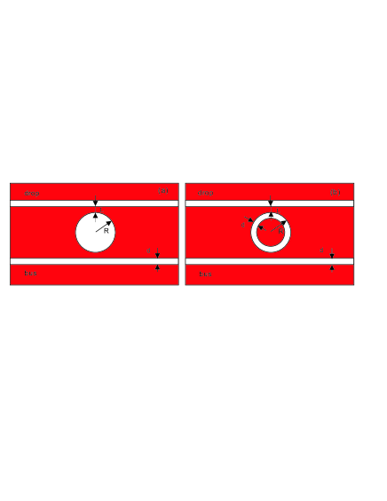
Consider firstly a resonant channel drop filter with an air circular disk resonator in a plasmon-polaritons metal, where the waveguide and the resonator are introduced by removing the metal with a specific shape. The corresponding structure is shown in Fig. 1 (a), where , and is the waveguide width, distance between the boundaries of the air disk and the waveguide, and the radius of the air disk resonator, respectively. The radium of the air disk is chosen as , and the dielectric function of the metal (Silver) is described by the loss Drude model:
| (1) |
where / is the relative permittivity at infinite/zero frequency, is the plasma frequency, and is the collision frequency. We choose , , and for the Drude model, which fits the experimental data quite well Palik (1985). The waveguide width, chosen as , is much smaller than the wavelength so that only the fundamental transverse magnetic () waveguide mode is excited. Our studies show, to realize a CDF system, that the mode waveguide is preferred. The reason is that, compared with the mode waveguide, it is much difficult to couple the energy from the waveguide to the resonator for the higher-order mode waveguide, which almost act as a perfect metallic waveguide.
Coupled mode or scattering theory are used to analyze theoretically the interaction of a cavity resonator with a waveguide system Manolatou et al. (1999); Xu et al. (2000). But these works consider waveguides with continuous translation symmetry and ignore waveguide dispersion. Waks et. al. derive an analytical coupled mode theory including waveguide dispersion , especially for a photonic crystal waveguide Waks and Vuckovic (2005). However, for such a SPP waveguide, the conventional coupled mode or scattering theory are also often suitable since the dispersion for the SPP waveguide is quite weak in the frequency region of interest, as well as for a optical fiber waveguide. According to the coupled mode theory, we can easily obtain the filter response of the system Manolatou et al. (1999)
| (2) | |||||
| (3) | |||||
| (4) | |||||
| (5) |
where is the resonant frequency, and are the decay rate due to loss and the rate of decay into the bus/drop waveguide, is the reflection from the input port, is the transmission through the bus and and represent the transmission into the left and right ports of the receiver. and , defined as the decay rates in the forward and backward direction, satisfy
| (6) |
In a travelling-wave mode, the power flows continuously in only one direction in the resonator. It can be easily obtained that the incident power in the bus in the forward direction is partially transferred to the receiver in the backward direction, limited only by the loss for the unloaded resonator, i.e., for the channel with resonant frequency , can be transferred completely into the drop waveguide. For a pure standing-wave mode, the resonant mode decays equally into the forward and backward propagating waveguide mode. From Eqs. (2)-(5), one knows that the maximum drop efficiency is , i.e, half the input power at resonant frequency can be dropped into the drop waveguide if the loss for the unloaded resonator is ignored.
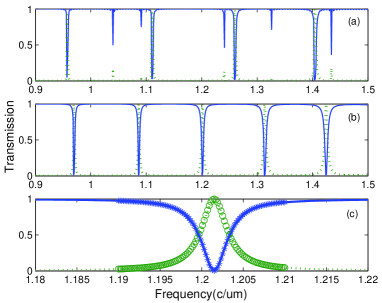
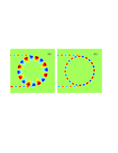
Look back to the channel drop filter system, as shown in Fig. 1 (a). Not only surface travelling resonant modes, but also standing wave modes in the air disk resonator will be excited. Our calculations show that the intrinsic quality factor () for the unload resonator is quite large and reaches if we ignore the loss of the metal, and the quality factor () for the filter system is about with the resonant frequency (normalized to light velocity in vacuum ) when the distance between the waveguide and resonator is . Basically, can increase if we enlarge . Based on the coupled mode analysis above, almost power can be dropped by the surface-travelling mode, while the drop efficiency at one output based on standing waves is quite small, at most . The spectral response after time steps, for , are shown in Fig. 2(a), where the solid and dotted line represent the transmission at the forward bus and backward drop waveguide, respectively. It can be seen from Fig. 2(a) that the light can be efficiently dropped for some frequencies. For some resonant frequencies, the drop efficiency is quite high, close to , due to the surface travelling mode. However, the drop efficiency, governed by the standing wave, is below , which is in agreement with results from coupled mode theory. Figure 3(a) shows the oscillation of the steady-state field distribution at a resonant frequency with , where almost all energy is dropped by a surface travelling resonant wave.
One important factor characterizing a channel drop filter is its channel isolation (), defined as , where and are the power of the selected channel transferred to the drop waveguide and the power remaining in the bus respectively. The channel isolation should be as large as possible to avoid the cross talk. For the resonator with a surface travelling mode mentioned above, is quite large and theoretically infinite if ignored the loss of the metal. However, for a single-mode standing wave resonator is quite small. It is possible to get a high for a single-mode travelling-wave resonant filter using two standing-wave modes. In this letter, to avoid exciting the standing-wave modes in the resonator, a channel drop filter with a ring resonator is investigated, as shown in Fig. 2(b). The width of the ring waveguide is same as the bus/drop waveguide and the outer radius of the ring resonator is also chosen as . Mechanism in this system is quite similar to the conventional ring resonator. Coupled mode theory tells us that a single-mode travelling wave resonator side-coupled to the bus and the receiver can fully transfer a channel at the resonant frequency from the bus to the receiver, only limited by .
The spectral response at both the forward bus (solid line) and backward drop waveguide (dotted line) are shown in Fig. 3(b) when . It can be seen from Fig. 3(b) that light can be almost completely dropped for resonant frequencies. The results for the resonant frequency , obtained by coupled mode theory, are shown in Fig. 3(c) by circled and asterisk lines. It can be seen from Fig. 3(c) that those obtained from coupled mode theory are consistent with the results by FDTD method. Combined with the resonant conditions (), the effective index () for the ring waveguide with the width of , is about for the resonant frequency from the FDTD results. However, the effective index for the straight waveguide with the same width is for the same resonant frequency. There is still no any good analytical approximate method to calculate the effective index of the ring waveguide when the working wavelength is close to the radius of the ring. Figure 4(b) shows the oscillation of the steady-state field distribution at a resonant frequency with , where almost of the field energy is transferred along the backward drop waveguide. However, the quality factor for the filter is quite slow, only about for the resonant frequency . Since the intrinsic quality factor for the unload resonator is much high, the quality factor of the channel drop filter can be increased if we enlarge the distance between waveguide and ring resonator, which also keeps a high drop efficiency. reaches when .
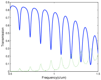
A metal () is always a loss material especially in the visible and infrared frequency region, which satisfies and . The loss problem for a straight SPP waveguide can be dealt with the first-order perturbation theory, which considers the imaginary part of permittivity as a perturbation for the real part of permittivity. Consider a channel drop filter with a ring resonator in a lossy plasmon-polaritons metal. If we take into account the loss of the metal, the quality factor for the unloaded resonant cavity decreases significantly. is only about for the cavity with a radius of . To increase the drop efficiency, we shorten the distance between the waveguide and the cavity in order to enlarge the coupling. We set the source and two detectors with a distance of with the center of the ring resonator in the propagation direction. For the channel drop filter system with , the quality factor of the channel drop filter is only , which leads to weak drop efficiency. The spectral response at both the forward bus (solid line) and backward drop waveguide (dotted line) are shown in Fig. 4. It can be seen from Fig. 4 that the drop efficiency is quite slow, as well as the quality factor. The drop efficiency becomes larger with increasing the resonant frequency. Since the quality factor for the filter becomes smaller with increasing the resonant frequency, based on the coupled mode theory, the drop efficiency will naturally increase.
In Conclusion, we have investigated channel drop filters in a plasmon-polaritons metal. Our results show that light can be efficiently dropped in these channel drop systems. The results obtained by FDTD method are consistent with the results from coupled mode theory. Without considering the loss of the metal, the quality factor of the channel drop systems reaches . However, the quality factor decreases significantly if we take into account the loss of the metal. For the channel drop system in a loss metal with , the maximum drop efficiency is about and the quality factor is only . Recently, many theoretical and experimental results show that using surface plasmon polaritons the scale of optoelectronic devices can be shrunk by at least an order of magnitude Smolyaninov et al. (2005). People used dielectrics with gains to compensate the loss of the metal Nezhad et al. (2004). However, the loss of the plasmon-polaritons metal is still a problem.
This work was supported by the Swedish Foundation for Strategic Research (SSF) on INGVAR program, the SSF Strategic Research Center in Photonics, and the Swedish Research Council (VR) under Project No. 2003-5501.
References
- Haus and Lai (1992) H. A. Haus and Y. Lai, J. Quantum Electron. 28, 205 (1992).
- Manolatou et al. (1999) C. Manolatou, M. J. Khan, S. Fan, P. R. Villenueve, H. A. Haus, and J. D. Joannopoulos, J. Quantum Electron. 35, 1322 (1999).
- Oda et al. (1991) K. Oda, N. Tokato, and H. Toba, J. Lightwave Technol. 9, 728 (1991).
- Little et al. (1997a) B. E. Little, S. T. Chu, H. A. Haus, J. Foresi, and J. P. Laine, J. Lightwave Technol. 15, 998 (1997a).
- Fan et al. (1998a) S. Fan, P. R. Villeneuve, J. D. Joannopoulos, and H. A. Haus, Phys. Rev. Lett. 80, 960 (1998a).
- Fan et al. (1998b) S. Fan, P. R. Villeneuve, J. D. Joannopoulos, and H. A. Haus, Opt. Express 3, 4 (1998b).
- Qiu and Jaskorzynska (2003) M. Qiu and B. Jaskorzynska, Appl. Phys. Lett. 83, 1074 (2003).
- Kim et al. (2004) S. Kim, J. Cai, J. Jiang, and G. P. Nordin, Opt. Express 12, 2356 (2004).
- Zhang and Qiu (2005) Z. Zhang and M. Qiu, Opt. Express 13, 2596 (2005).
- Rotman (1951) W. Rotman, Proc. IRE 39, 952 (1951).
- Hurd (1954) R. A. Hurd, Can. J. Phys. 32, 727 (1954).
- Elliott (1954) R. S. Elliott, IRE Trans AP-2 pp. 71 –81 (1954).
- Pendry et al. (2004) J. B. Pendry, L. Martin-Moreno, and F. J. Garcia-Vidal, Science 305, 847 (2004).
- Weeber et al. (1999) J. C. Weeber, A. Dereu, C. Girard, J. R. Krenn, and J. P. Goudonnet, Phys. Rev. B 60, 9061 (1999).
- Dickson and Lyon (2000) R. M. Dickson and L. A. Lyon, J. Phys. Chem. B 104, 6095 (2000).
- Quinten et al. (1998) M. Quinten, A. Leitner, J. R. Krenn, and F. R. Aussenegg, Opt. Lett. 23, 1331 (1998).
- Maier et al. (2003) S. A. Maier, P. G. Kik, H. A. Atwater, S. Meltzer, E. Harel, B. E. Koel, and A. A. G. Requicha, Nat. Mater. 2, 229 (2003).
- Taflove (2000) A. Taflove, Computational Electrodynamics: The Finite-Difference Time-Domain Method (Artech House INC, Norwood, 2000), 2nd ed.
- Guo et al. (2001) W. Guo, W. Li, and Y. Huang, IEEE Microwave Wireless Components Lett. 11, 223 (2001).
- Qiu (2005) M. Qiu, Microwave Opt. Techn. Lett. 45, 381 (2005).
- Little et al. (1997b) B. E. Little, J. P. Laine, and S. T. Chu, Opt. Lett. 22, 4 (1997b).
- Palik (1985) E. D. Palik, Handbook of Optical Constants of Solids (Academic, New York, 1985).
- Xu et al. (2000) Y. Xu, Y. Li, R. K. Lee, and A. Yariv, Phys. Rev. E 62, 7389 (2000).
- Waks and Vuckovic (2005) E. Waks and J. Vuckovic, Opt. Expres 13, 5064 (2005).
- Smolyaninov et al. (2005) I. I. Smolyaninov, Y. J. Huang, and C. C. Davis, Appl. Phys. Lett. 87, 241106 (2005).
- Nezhad et al. (2004) M. P. Nezhad, K. Tetz, and Y. Fainman, Opt. Express 12, 4072 (2004).