Directional interacting whispering gallery modes in coupled dielectric microdisks
Abstract
We study the optical interaction in a coupled dielectric microdisks by investigating the splitting of resonance positions of interacting whispering gallery modes (WGMs) and their pattern change, depending on the distance between the microdisks. It is shown that the interaction between the WGMs with odd parity about -axis becomes appreciable at a distance less than a wavelength and causes directional emissions of the resulting interacting WGMs. The directionality of the interacting WGMs can be understood in terms of an effective boundary deformation in ray dynamical analysis. We also discuss about the oscillation of the splitting when the distance is greater than a wavelength.
pacs:
42.55.Sa, 42.65.SfI Introduction
In spherical and cylindrical dielectric cavities high- modes are the whispering gallery modes (WGMs) in which light rays circulate along the curved inner boundary of the cavities, reflecting from the boundary with an incident angle always greater than the critical angle for total internal reflection, thus remaining trapped inside the cavitiesMcC92 ; Cha96 . There are only minute isotropic emissions of light caused by evanescent leakage. For the applications to optical communication and optoelectric circuit, this isotropic emission is not desirable, rather directional emission is much more useful and effectiveCha96 .
As a simple system for directional emissions, slightly deformed microcavities have been proposed, and directional emissions, tangential from the boundary points with the highest curvature, are achieved. In the ray dynamical viewpoint, as being slightly deformed, some invariant tori are destroyed in the Poincaré surface of section (PSOS), but the Kolmogorov-Arnold-Moser (KAM) tori still confine the rays supporting the WGMs. In this case, the tunneling process, through the lowest dynamical barrier, to the critical line for the total internal reflection can explain the tangential emissionsCha96 ; Mek95 .
When the cavity boundary is highly deformed, the PSOS shows a global chaotic sea with very small integrable regions (islands). In this strong chaotic case, the directional emissions can be found in scarred resonancesScar and quasiscarred resonancesLee04a . Unlike the slightly deformed case, the direction of emission in these resonances can be deviated from the tangential, and is well explained by the unstable manifold structure near the critical line for total internal reflectionSch03 and the Fresnel filtering effectRex02 . In addition, there are special boundary shapes for generating unidirectional emission, spiral-shapedSpiral and rounded triangle-shapedtri04 . We note that the efforts for directional emissions are mainly based on the deformation of boundary shapes.
In this paper we show, through a numerical study on the interacting WGMs in a coupled identical disks, that a mode-mode interaction can generate directional emissions. The interaction between two WGMs is parameterized by the distance between two disks, and it turns out that the strength of the interaction between WGMs with odd parity about -axis becomes appreciable at a distance less than a wavelength, which are evident from the results on variation of resonance positions and patterns. In order to explain the resulting directional emission, we assume that the circular boundary shapes would be effectively deformed due to the mode-mode interaction. With this assumption the ray dynamical analysis gives a good explanation for the degradation of Q-factor and the enhancement of directional emissions. In addition, when the WGMs are weakly coupled, the resonance positions show an oscillating behavior depending on the distance.
The paper is organized as follows. In Sec. II we illustrate our system, i.e., a coupled dielectric microdisks. The numerical results for the strongly interacting WGMs and a ray dynamical model with an effective deformation are presented in Sec. III. The behavior of weakly interacting WGMs is discussed in Sec. IV. Finally, we summarize results in Sec. V.
II Coupled dielectric microdisks
As a simple system for the study on interacting WGMs, we take coupled dielectric microdisks. In this system, the strength of the interaction can be controlled by adjusting the distance between two disks. It is well known that the WGMs of a single dielectric microdisk are two-fold degenerate due to the circular symmetry, and are classified by the angular momentum mode index and the radial mode index Cha96 . Therefore, in the coupled microdisks, the WGMs would show an approximate four-fold degeneracy when the distance between the disks is very large, equivalently, the interaction between WGMs is negligible. As the distance is getting smaller, the WGM in one microdisk starts to know the existence of the WGM in the other microdisk, then the system is no longer circular symmetric, and the four-fold degenerate resonance positions start to split each other, and the degree of the splitting measures the strength of the interaction between the WGMs.
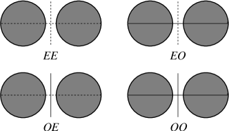
Figure 1 shows the four symmetry classes of coupled dielectric microdisks. The system has two symmetry lines and the former letter is even(odd) if the wave function is even(odd) with respect to and the latter refers to .
In practical calculation of the interacting WGMs in the coupled dielectric microdisks, we use the boundary element method (BEM) which is effective when the boundary is strongly deformed from a circular shape and the cavities are coupledWie03 . In this paper, we focus on the TM polarization where both the wavefunction and its normal derivative are continuous across the boundary. The radius of disks is , the distance between two dielectric disks is , and and are the refractive indices inside and outside disks, respectively. We set throughout the paper.
III Strongly interacting WGMs
In this section we present numerical results on the variation of resonance positions and patterns of the strongly interacting WGMs, i.e., the case of the short distance, . As mentioned before, we expect that the four-fold degenerate WGMs would start to split each other due to the interaction between WGMs as the distance decreases. As a result of the interaction the directional emissions appear in the interacting WGMs with odd parity about -axis. We explain this directionality by assuming an effective deformation of boundary in ray dynamical analysis. In the practical BEM calculation, we take 12 elements per a wavelength inside ().
III.1 Variation of resonance positions and patterns
Numerical calculation is performed for the WGM of mode index with . Exact resonance positions of the WGM in an isolated microdisk can be obtained from the matching conditions between the Bessel function and the Hankel function of the first kind which are inner and outer radial solutions of the Helmholtz equation, respectively. The exact resonance position of is where is the vacuum wavenumber. The very small value of means high factors from the relation . Unfortunately, it is very difficult to get the exact imaginary values from the BEM, for example, when we take 12 elements per , the BEM calculation for the isolated microdisk gives for . In spite of the restriction in the precision of resonance positions, we rely on the BEM calculation in analyzing the interacting WGMs based on the following reasons. First, the change of does not give any visible variation in resonance patterns. Second, the BEM calculation would give a correct result when the variation of resonance positions exceeds the precision limit, .
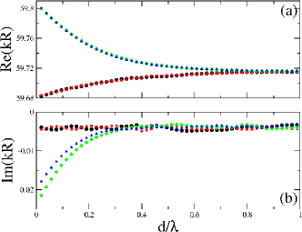
Figure 2 shows the variation of resonance positions of the interacting WGMs. The four fold degenerate state starts to split into two groups at in and at in . Here we can see that the resonances with odd parity about axis(, modes) show larger variations, indicating that the WGMs in the resonances are strongly coupled. We note that the values of , modes increase with decreasing . The increment of implies a reduction of effective boundary perimeter, and the interaction between WGMs in the , modes is, thus, repulsive. From the same argument, we conclude that the interaction in the , modes is weakly attractive. This result will be used in determining the effective deformation in the ray model in the next subsection. As shown in Fig. 2 (b) the values of , modes decrease with decreasing , implying the degradation of Q-factor due to the repulsive interaction. Therefore, we can expect that the emission of the , modes would be stronger than those of the , modes. From the viewpoint of the effective boundary deformation due to the repulsive interaction, we can understand the difference of the onset points of the splitting in and . In a slightly deformed cavity, the rays supporting the WGM are completely confined by the KAM tori, resulting no drastic reduction of -factor. As the cavity is more deformed, the KAM tori would be broken and the rays can diffusively escape along the unstable manifolds, and then the -factor, equivalently , would decrease rapidly.
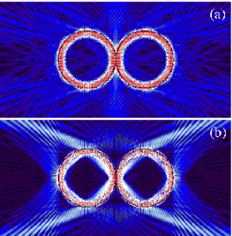
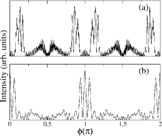
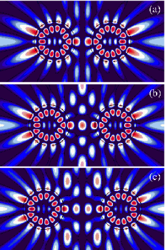
From the splitting behavior of the resonance positions, we can expect that the resonance patterns of and modes would be different from those of and modes. In Fig. 3 the resonance patterns of the interacting s are shown when the distance is . The resonance position of mode shown in Fig. 3 (a) is and, as expected from the small absolute value of , the very small evanescent leakage is showncom01 . However, as shown in Fig. 3 (b), the resonance pattern of mode () shows clear directional emissions, reflecting the strong repulsive mode-mode interaction. Its far field emission pattern is plotted in Fig. 5 (a) where the four strong directional emissions are clearly seen. We find that the directionality of the emission pattern is insensitive to the distance , although the strength of emissions decreases with increasing .
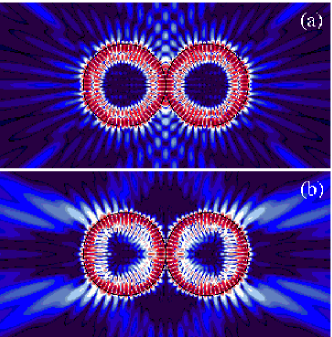
In and modes, the strong directional emission by the repulsive mode-mode interaction is a generic feature, but the emission directions are closely related to the reflective index . As an example, the resonance patterns of and modes in the interacting s, when and , are shown in Fig. 4. As expected, four strong directional emissions are shown only in the resonance pattern in Fig. 4 (b), and the two beams emitted from one disk are almost parallel to -axis. Note that the direction of emission is quite different from that of the interacting in Fig. 3 (b). The corresponding far field emission pattern is shown in Fig. 5 (b) where we confirm the two directional emissions along -axis and clear interference pattern of the parallel beams.
In the next subsection we will introduce a ray dynamical model to explain the dependence of the directionality of emissions in the interacting WGMs with and parities.
III.2 Ray dynamical model : Effective deformation
In a circular disk, the ray dynamics is simple. The rays with incident angles greater than the critical angle, , are perfectly confined in the disk by the total internal reflection, while the other rays escape isotropically due to its rotational symmetry. With a simple combination of this trivial ray dynamics, it is impossible to explain the directionality of the interacting WGMs shown in the previous subsection.
We recall that the interaction between WGMs are repulsive in and modes. In fact, this originates from the constraint that the field value at or on -axis should be zero due to the odd parity about -axis. As a result, the intensity spots confronting each other near would shift repulsively, and the structure of the whole intensity spots in a WGM would be slightly deformed from circle. In order to incorporate this effect of the repulsive interaction into the ray dynamics, we consider a slightly deformed circular boundary which can support the slightly deformed WGM similar to one of the interacting WGMs.
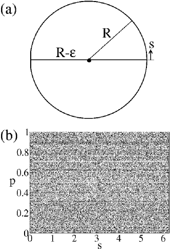
As a simple ray dynamical model containing the effect of the repulsive interaction, we consider a circular disk with a cut as shown in Fig. 6 (a). The deformation parameter is which is the reduced length of the radius by the cut. Figure 6 (b) shows its PSOS representing the trajectory of a ray starting from one point in phase space , where is the boundary coordinate and , being the incident angle, without the consideration of the refractive escape. Since the circle with a cut is a discontinuous deformation(non-KAM system), this model cannot describe weakly deformed case where the rays supporting WGM are still confined in KAM tori. So, our model is more suitable to a moderately deformed case where the rays supporting WGM can diffusively escape. The ray can change their incident angle only through the bounce on the cut, and eventually the ray trajectory fill up the whole phase space, even though there are so many marginally stable lines. The broken lines at and represent the families of the marginally stable triangular and rectangular periodic orbits, and the gaps of lines correspond to the cut of the boundary.
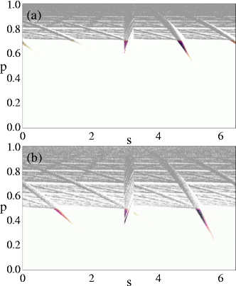
The dielectric microcavities are open systems where rays can refractively escape from the microcavities, and the escape rate are determined by the Fresnel equationsHaw95 . In order to understand the emission direction of rays, we obtain the survival probability distributions in both cases of and which are shown in Fig. 7 (a) and (b), respectively. The gray points in Fig. 7 correspond to the rays with normalized probability greater than in the time range of with a time scale as the length of ray trajectory, and the rays start from a uniform ensemble of initial positions in the phase space. The pattern of the survival probability distribution reveals the openness structure on the unstable manifold background near the critical lines, , for the total internal reflection. The directionality of emissions and the emitting part of boundary are explained by the pattern below the critical line. The color plots below the critical lines in Fig. 7 (a) and (b) illustrate how the long-lived rays supporting the WGMs can escape. We find that the long-lived rays refractively escape through the unstable manifold structure arising in the survival probability distribution. As mentioned before, the ray far above the critical line changes its angular momentum only when bouncing from the cut and, depending on the bouncing position on the cut the angular momentum can increases or decreases, in other words, the angular momentum diffuses to other values. From repetition of this diffusion process, the ray can reach below the critical line and eventually escape the microcavity. The ensemble of the above escape process makes the color plots. The darkness of the color plots represents the population of the ensemble.
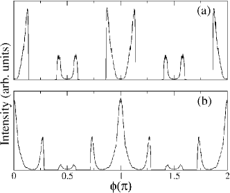
The colored spikes below the critical line() in Fig. 7(a) correspond to the rays following the diamond-typed period orbit inside the microcavity and indicate that the ray emission from about is very strong for the counterclockwise circulating rays(). These are consistent with the resonance pattern shown in Fig. 3 (b) where the faint diamond structure is seen inside the microdisks and the strong emission comes out from about of the right microdisk. If we consider another effective deformed microcavity to simulate the interacting WGMs, we can get the resulting emission pattern shown in Fig. 8 (a) where we neglect the emission from the cut. This ray dynamical result is very similar to the far field emission pattern of Fig. 5 (a) except the interference oscillation in peaks. The same discussion is valid for the case of case shown in Fig. 7 (b). The resulting emission pattern is given in Fig. 8 (b), and this explains well the far field pattern of the interacting WGMs shown in Fig. 5 (b).
Although the deformed disk in Fig. 6 (a) is a non-KAM system, this explains well the insensibility of the directionality of emissions to the distance . The longer distance corresponds to the smaller value. In this case, although the average escape rate and the emitting part of the boundary would decrease, it is clear that the emission directions and the emitting positions on the boundary are essentially invariant. However, the mode-mode interaction would create a continuous deformation, i.e., the system would be a KAM system. In a KAM model, even if the rays supporting the WGM are confined in KAM-tori, it is still possible for the rays to reach chaotic sea through the dynamical tunneling, and then diffuse along the unstable manifolds to the critical linePod05 . The unstable manifold structure near the critical line in the KAM model would be similar to that of the non-KAM model if the global boundary shapes of both models are almost identical. Therefore, both models would give the essentially same emission directionality.
IV Weakly interacting WGMs
When the distance is larger than , the interaction between WGMs becomes very small. The strength of the small interaction can be measured by the deviation of resonance position from that of isolated corresponding WGM as done for the strongly interacting WGMs in the previous section. Figure 9 (a) shows the variation of the resonance position in the range of for the interacting s with . It is shown that the resonance positions of both (black circle) and (red square) modes oscillate with the period . The oscillatory behavior also appears for and modes. The interference effect of emitted waves from the WGMs seems to be responsible for the oscillatory behavior. As pointed out in the previous section, the BEM calculation, however, has the precision limit of . We note that the amplitude of the oscillations is almost same order with the precision limit. So, we have to be careful to accept the oscillatory behavior as a real phenomenon, because it can be a numerical artifact. To check this, we performed the same calculation for the interacting s () which are relatively low-Q resonance modes. Since the emission of the is stronger than the case, we expect the variation of the resonance position would be larger than the precision of BEM.
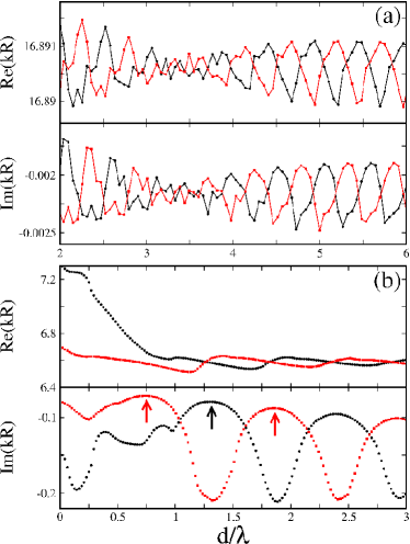
The exact resonance position of the in an isolated circular disk is and in the BEM giving the same precision limit of . For the interacting s, the variations of resonance positions for and modes are shown in Fig. 9 (b). When , both real and imaginary parts of oscillate with a period and the oscillation amplitude is much greater than the precision limit of the BEM, which supports that the oscillatory behavior of the interacting in Fig. 9 (a) would be a real phenomenon, not a numerical artifact. We note that the oscillation of the resonance position of mode is out of phase with that of mode in both and . The resonance patterns at the local maxima of , corresponding to minimum leakages of the system, denoted by arrows in Fig. 9 (b) are shown in Fig. 10, and these explain why the oscillations of resonance positions of and modes are out of phase and have a period . The internal patterns of the resonances are almost invariant, and the characteristic difference is the number of intensity spots on the horizontal axis between two disks which increases one by one. Odd and even number of spots appear in and modes, respectively. Roughly we can understand this oscillation behavior as the degree of the accordance with the quantization condition of the unstable periodic orbit lying on the horizontal axis between two disks even though the boundary condition on the ends of the period orbit is not trivial. In fact this kind of explanation is valid only for relatively low case where the interference on the unstable orbit dominates, and other inference effects are negligible. In the high case many beams emitted from the intensity spots inside disks take part in the interference process, and the resulting oscillation of each symmetry mode would show more complicated behavior in its period and amplitude.
V Summary
In the coupled disks system, we have shown that the strongly interacting WGMs with odd parity about -axis gives good directional emissions, and the directions of the emissions are determined by the refractive index of the dielectric disks. This finding has been well explained by an effective boundary deformation in ray dynamical model. It is also shown that the resonance positions of the weakly interacting WGMs oscillate depending on the distance between two microdisks, and this oscillation can be understood as the result of interference of emitted beams from the WGMs.
Acknowledgments
This work is supported by Creative Research Initiatives of the Korean Ministry of Science and Technology.
References
- (1) S. L. McCall, A. F. J. Levi, R. E. Slusher, S. J. Pearton, and R. A. Logan, Appl. Phys. Lett. 60, 20 (1992);Y. Yamamoto and R. E. Slusher, Physics Today 46, 66 (1993).
- (2) Optical Processes in Microcavities, edited by R. K. Chang and A. J. Campillo (World Scientific, Singapore, 1996).
- (3) A. Mekis, J. U. Nöckel, G. Chen, A. D. Stone, and R. K. Chang, Phys. Rev. Lett. 75, 2682 (1995); J. U. Nöckel, A. D. Stone, G. Chen, H. L. Grossman, and R. K. Chang, Opt. Lett. 21, 1609 (1996); J. U. Nöckel and A. D. Stone, Nature 385, 45 (1997).
- (4) E. J. Heller, Phys. Rev. Lett. 53, 1515 (1984); S.-B. Lee, J.-H. Lee, J.-S. Chang, H.-J. Moon, S. W. Kim, and K. An, Phys. Rev. Lett. 88, 033903 (2002); C. Gmachl, E. E. Narimanov, F. Capasso, J. N. Baillargeon, and A. Y. Cho, Opt. Lett. 27, 824 (2002); T. Harayama, T. Fukushima, P. Davis, P. O. Vaccaro, T. Miyasaka, T. Nishimura, and T. Aida, Phys. Rev. E 67, 015207(R) (2003).
- (5) S.-Y. Lee, S. Rim, J.-W. Ryu, T.-Y. Kwon, M. Choi, and C.-M. Kim, Phys. Rev. Lett. 93, 164102 (2004).
- (6) H. G. L. Schwefel, N. B. Rex, H. E. Tureci, R. K. Chang, A. D. Stone, T. Ben-Messaoud, and J. Zyss, J. Opt. Soc. Am. B 21, 923 (2004); S.-Y. Lee, J.-W. Ryu, T.-Y. Kwon, S. Rim, and C.-M. Kim, arXiv:nlin.CD/0505040 (2005).
- (7) N. B. Rex, H. E. Tureci, H. G. L. Schwefel, R. K. Chang, and A. D. Stone, Phys. Rev. Lett. 88, 094102 (2002);
- (8) G. D. Chern, H. E. Tureci, A. D. Stone, R. K. Chang, M. Kneissl, and N. M. Johnson, Appl. Phys. Lett. 83, 1710 (2003); M. Kneissl, M. Teepe, N. Miyashita, N. M. Johnson, G. D. Chern, and R. K. Chang, Appl. Phys. Lett. 84, 2485 (2004); T. Ben-Messaoud and J. Zyss, Appl. Phys. Lett. 86, 241110 (2005).
- (9) M. S. Kurdoglyan, S.-Y. Lee, S. Rim, and C.-M. Kim, Opt. Lett. 29, 2758 (2004).
- (10) J. Wiersig, J. Opt. A : Pure Appl. Opt. 5, 53 (2003); S.-Y. Lee, M. S. Kurdoglyan, S. Rim, and C.-M. Kim, Phys. Rev. A 70, 023809 (2004).
- (11) The intensity outside disks of Fig. 3 (a) is much smaller than that of Fig. 3 (b) but for convenient sake, we show the near field intensity patterns with different intensity scale. It is the same as Fig. 4.
- (12) J. F. B. Hawkes and I. D. Latimer, Lasers : Theory and Practice, (Prentice Hall, 1995).
- (13) V. A. Podolskiy and E. E. Narimanov, Opt. Lett. 30, 474 (2005).