Development of a high-efficiency pulsed slow positron beam for measurements with orthopositronium in vacuum.
Abstract
We have developed a high-efficiency pulsed slow positron beam for experiments with orthopositronium in vacuum. The new pulsing scheme is based on a double-gap coaxial buncher powered by an RF pulse of appropriate shape. The modulation of the positron velocity in the two gaps is used to adjust their time-of-flight to a target. This pulsing scheme allows to minimize non-linear aberrations in the bunching process and to efficiently compress positron pulses with an initial pulse duration ranging from 300 to 50 ns into bunches of 2.3 to 0.4 ns width, respectively, with a repetition period of 1 . The compression ratio achieved is , which is a factor 5 better than has been previously obtained with slow positron beams based on a single buncher. Requirements on the degree, to which the moderated positrons should be mono-energetic and on the precision of the waveform generation are presented. Possible applications of the new pulsed positron beam for measurements of thin films are discussed.
keywords:
Pulsed slow positron beam, Buncher, OrthopositroniumPACS:
41.85.C; 36.10.D; 41.75.F, , , , , , , , , ,
1 Introduction
Orthopositronium (), the triplet -bound state, is a particularly interesting system for a search for new physics [1] - [5] and for high precision tests of QED [6] -[8]. New experimental results on this system are expected by improving the sensitivity of the previously developed techniques based on the production in a low density SiO2 target [9]. Other possible experiments, such as the search for mirror type dark matter via the decay mode [10]-[12], precise measurements of the decay rate [13] and others [14], require the production and subsequent decay of to occur in vacuum. For these experiments a specially designed slow positron beam operating in a pulsed mode with a repetition period of has been constructed. The construction of the beam has to compromise two main design goals [10]: i) the time of the primary positron collection has to be comparable with the repetition period in order to get the highest pulsing efficiency (the ratio of beam intensities in the pulsed and DC modes) and to enhance the signal-to-noise ratio; ii) a high beam compression factor of has to be achieved in order to obtain a positron pulse width of a few ns and to suppress background for tagging of production.
Various techniques to produce pulsed positron beams have been reported with the main focus so far on material science applications, for a review, see e.g. [15, 16]. The Munich group uses a pulsing scheme with two bunchers [17]. A saw-tooth shape pulse is used in a pre-buncher to produce 2 ns pulses from the initial pulse of 13 ns. Then, a 50 MHz chopper is used to eliminate unbunched positrons and to increase the signal to background ratio. Finally, a 50 MHz RF main buncher produces longitudinal compression of pulses from 2 ns to 150 ps (FWHM) duration. A similar pulsing scheme is used by the Tsukuba group [18]. For the vacuum experiments mentioned above, this method requires a wide time window of chopping, and accordingly, the positron collection efficiency from an initial DC beam would become less than 1%.
A different pulsing method has recently been considered by Oshima et al. [19]. The main idea is the same as for the RF method: the time-of-flight for each positron is adjusted according to the time it arrives at the starting point of the acceleration. However, instead of applying a sinusoidal-like RF field, a more suitable pulse shape of the electric field, with an approximate inverse parabolic function of time, is applied to a single gap for the positron velocity modulation [20]. This method has been further developed by Iijima et al. [21] for material measurements in which the lifetime of orthopositronium atoms is close to its vacuum value of 142 ns. For these applications it is necessary to modify the originally proposed technique in order to generate higher intensity positron beams by accumulating positrons over a wider time interval, even though the bunch width becomes larger, but is still much less than the typical measured timing intervals of 100 ns. Using a high permeability buncher core, a bunch width of 2.2 ns (FWHM) for 50 ns collection time and a repetition period of 960 ns has been achieved [21]. One of the problems encountered is the limitation of the voltage supplied by a post-amplifier to the buncher.
In this paper we describe a double-gap coaxial buncher powered by an RF pulse of appropriate shape, which is produced by an arbitrary waveform generator (AWG) and by a post-amplifier. This pulsing method allows to reduce the influence of aberrations of the bunching pulse shape in comparison with methods using a sinusoidal RF voltage and to achieve a compression ratio limited mainly by the intrinsic energy spread of the initial positrons. In comparison with the one gap buncher method, see e.g. Ref. [19], the present scheme requires lower bunching voltage and less post-amplifier power 111More details on a pulsing system with a single-gap velocity modulation can be found in ref. [19, 20].
The rest of this paper is organized as follows: The beam prototype and the new pulsing system are described in Section 2. The description of simulations used to design the pulsing system is given in Section 3. In Section 4 the results obtained with the pulsed beam are presented and the requirements for the system components are discussed. Possible applications of the developed pulsed beam for measurements in material research are discussed in Section 5. A summary is given in Section 6.

2 The pulsed slow positron beam
2.1 The actual beam
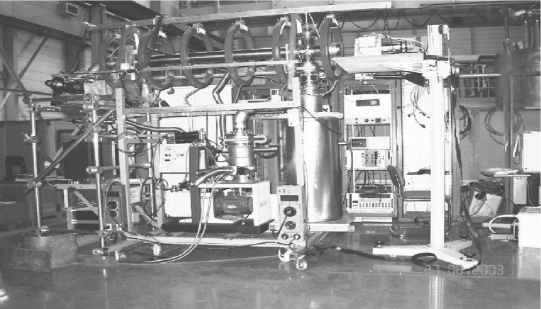
The preliminary design of the present pulsed slow positron beam has been reported in [10]. Our primary consideration is that the system should be of the magnetic transport type because this provides the simplest way to transport a slow positron beam from the positron source to its target [22]. Fig. 1 and Fig. 2 show the schematic illustration of the developed pulsed slow positron beam and the photgraph of the actual beam, respectively. The DC slow positrons are produced by moderating the fast positrons emitted in -decays of the radioisotope source 22Na. This source, with a relatively small activity ( Ci) was prepared by bombarding a 150 m thick foil of pure Al with a 590 MeV proton beam at the PSI accelerator (Paul Scherrer Institute, Switzerland).
The moderator, a tungsten W(100) single crystal foil with a thickness of 1 , is prepared in situ by annealing it at 2000oC (see Section 4). A few eV positrons from the moderator are accelerated to 30 eV and are separated from the fast unmoderated positrons by a 90o curved B-field, serving as a velocity filter. The eight coils provide a quasi-uniform longitudinal magnetic field of 70 Gauss to guide positrons down to the target - a microchannel plate (MCP, Hamamatsu F4655-12), located at the end of the beam line and used for positron detection. The beam energy can be varied up to a few kV simply by applying the desired electrostatic potentials to the beam drift tubes.

The positron pulsing section shown in Fig. 1 consists of a chopper, the drift
tubes, and a buncher. The latter is constructed in such a way that its internal tube (the
buncher electrode) forms a coaxial line of 50 impedance with the external vacuum
pipe. The buncher internal tube length of 135 cm is determined by the distance-of-flight
of positrons entering the buncher during the initial pulse and by their energy. For the
initial pulse of 90 ns the repetition period can be varied from 220 ns to infinity.
Initial positron pulses with the desired duration are formed with the chopper grid placed
4 mm downstream of the moderator foil, as shown in Fig. 3.
The potential difference 5 V between the moderator film and the grid is used
for repelling the slow eV positrons emitted from the moderator. When the
rectangular shaped chopper pulse of a given duration (50 - 300 ns, produced by a standard
fast-signal generator), is applied to the grid with an amplitude of about 5V, the
moderated positrons come through and are accelerated in the gap between the chopper grid
and the first drift tube.
2.2 The pulsing scheme for the buncher
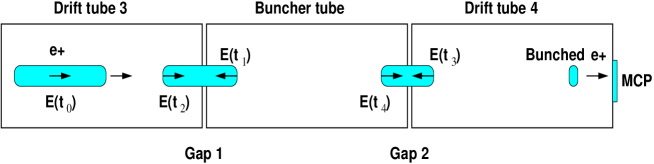
The principle of the positron pulsing method is illustrated in Fig. 4. A non-linear time-varying electric field in the first gap (Gap1) between the drift tube 3 and the bunching electrode modulates the velocity of positrons in such a way, that those (initially chopped and accelerated) positrons which arrive early are decelerated at the gap, while those which reach the gap later are accelerated. In the second gap (Gap2) between the buncher and drift tube 4 the same procedure is repeated. The chopper pulse is synchronized with the AWG trigger signal such that the chopped initial positrons passing the bunching electrode receive the correct bunching voltage from the corresponding part of the bunching pulse. Finally, the initially chopped positron pulse arrives at the MCP target as a bunch of a small width.
The bunching voltage of the designed shape is produced by the arbitrary waveform generator (AWG-510, Tektronix). The AWG output pulse is then amplified by the post amplifier 100A250A (Amplifier Research) and is applied to the bunching electrode. The amplifier has an output power of 100 W and a bandwidth of 10 kHz - 250 MHz, allowing to drive the 50 coaxial buncher with a pulse amplitude up to V without saturation. The time profile of the bunched positrons at the MCP position is measured by using the MCP signal as the TDC-START and the AWG signal as the STOP; the STOP signal is also used to trigger the chopper pulse.
3 Design of the pulsing system
The simulations of the E- and B-fields, the beam transport and the velocity modulation of positrons were performed with the GEANT4 [24] and 3D-Bfield [25] codes with the goal to minimize the time width of the bunch and to optimize the shape of the bunching pulse.
The optimal shape and duration of the bunching pulse was calculated for the given initial positron pulse duration by taking into account the following criteria:
-
•
the amplitude of the RF bunching pulse should be within 80 V,
-
•
after the velocity modulation positrons should arrive at the target as a bunch within a time spread of ns,
-
•
absence of significant non-linear distortions of the beam phase-space at the target position
For the first gap and for an initial pulse of e.g. 300 ns, a parabolic time-varying potential changing from -60 V (decelerating part) to +30 V has been chosen, as shown in Fig. 5. The time dependence of the potential at the central electrode of the buncher at times ns can then be calculated, solving the corresponding equations with an iterative procedure under the condition that positrons arrive at the target simultaneously and that the potential at the electrode at the end of the bunching pulse returns to its initial value -60 V. In Fig. 5 the resulting shape of the bunching voltage is shown for both gaps.
In reality, the bunching pulse shape differs from its ideal theoretical shape, mostly due to the finite frequency bandwidth of the post-amplifier and due to non-ideal matching of the coaxial buncher curcuit to 50 impedance. To estimate the effect, the response of the 100A250A amplifier was simulated according to its circuit characteristics [26]. The residual shape is defined as , where is the input signal supplied by the AWG with unit amplitude and is the amplifier output pulse calculated for unit gain.

It was found that for an initial pulse duration of 300 ns the deviation of the response from the ideal shape shown in Fig.5 is not more than about 1% over the full bunching pulse duration. The simulations show, that such a signal deviation results in a negligible distortion of the bunched positron pulse shape. The FWHM of the corresponding distribution has been increased by less than 2%. However, for shorter initial pulses ( ns ), deviations up to about 5% have been observed. This will result in a significant degradation of the FWHM and shape of the positron pulses. These results mean that the theoretical shape of the bunching pulse must be reproduced within about 1%. For an initial positron pulse duration of more than 100 ns this is achievable.

In Fig. 6 simulated time distributions of bunched positrons at the target are shown for different cuts on the longitudinal kinetic energy of positrons emitted from the moderator. The best time resolution with the new bunching method is about 2.1 ns (FWHM) for an initial pulse duration of 300 ns. It is also seen that the shape and width of the distributions are affected by the cut, i.e. by the degree to which the moderated positrons are mono-energetic, as expected from Liouville’s theorem.
4 Experimental results
4.1 Moderated positrons
It is well known that the spectrum of the longitudinal energy of moderated positrons strongly depends on the quality of the moderator and can be significantly improved by annealing the W-film in situ, see e.g. [23]. The moderator annealing in our setup was performed at 2000oC by bombarding the foil with an electron beam ( 25 W, 10 kV) for about 10 minutes in a vacuum of mbar.
Fig. 7a shows the DC positron intensity as a function of the potential difference between the moderator and the chopper grid. The longitudinal energy spectra are obtained from the derivatives of the corresponding intensity curves and are shown in Fig. 7b. The spectra are taken before, h after and two days after the annealing. It is seen that the positron yield increases due to annealing almost by a factor two. The FWHM of the energy distributions also changes from 3 eV obtained before to 2 eV measured after annealing. The spectra taken two days after annealing illustrate degradation of the moderator surface through interactions with a residual gas, which results in a broadening of the energy spectrum and a more isotropic re-emission of the positrons, i.e. in an increase of the beam emittance.

4.2 Positron bunch width
In Fig. 8 the measured time distributions of pulsed positrons at the target for are shown for an initial pulse of 90 ns and for different values of the retarding voltage between the moderator and the chopper grid. It is seen that the FWHM of the distributions is very sensitive to the energy spread of the moderated positrons changing from 1.4 ns to 0.63 ns, for V ( V) and V ( V), respectively. It should be noted, that the measurements shown in Figure 7 were performed by the retarding potential method, using the grid as an energy analyzer. However, due to the inhomogeneity of the electric field formed by the grid, this method probably does not have an energy resolution better than eV and a significant contribution to the FWHM of the positron energy spectra can be expected.
The measurement results demonstrate that the degree, to which the positrons emitted from the moderator are mono-energetic, is an important parameter. Thus, it is crucial to have a well-conditioned stable moderator in order to get a high performance of the beam. This observation is in qualitative agreement with the results of simulations. 222The detail comparison of beam simulations and measurement results will be reported elsewhere.


In Fig. 9a, b the measured time distributions of positrons arriving at the MCP are shown for initial positron pulse durations of 300 ns and 120 ns, respectively. The FWHM of the distributions are estimated to be 2.3 and 1.4 ns. These values are comparable with those expected from Monte Carlo simulations, see e.g. Fig. 6d. The compression ratio is , which is a factor 5 better than the values previously obtained by Iijima et al. [21], reporting a compression from 50 ns to 2.2 ns, and by Tashiro et al. [27], reporting a compression from 30 ns to 1.4 ns, respectively. For the bunch width of ns and a repetition period of our pulsing efficiency is 31 %, which is also a factor 6 better than reported in [21].

It should be noted, that the peak to (flat) background ratio () of the distributions shown in Fig.9a,b is in agreement with expectations from the accidental coincidences of START and STOP signals from i) two different positrons, mostly due to the MCP detection inefficiency, or ii) from non-positron related events due to the MCP noise. However, the non-Gaussian tails of the distributions in Fig.9a,b (see also Fig. 10) are slightly worse than expected from simulations. There are several contributions to these tails due to: i) the angular distribution of the moderated positrons and the fact that they are not mono-energetic, ii) the extraction of slow positrons from the moderator, iii) deviations of the pulse applied to the bunching electrodes from the calculated ideal shape, iv) heterogeneous electric and magnetic fields, v) time jitter of the detecting electronics, etc.
5 Possible applications of the pulsed beam
It is well known that positron annihilation lifetime spectroscopy (PALS) based on intense pulsed positron beams with a bunch width shorter than 1 ns is useful for many interesting applications, such as studies of polymers, coatings, measurements of porosity of thin films, etc [28]. In these studies information on a sample structure is extracted from the results of the lifetime measurement of formed inside the sample. The vacuum value of the lifetime is shortened by collisional pick-off annihilation and ranges typically from a fraction of a ns to tens of ns, see e.g. [28]. For high quality PALS spectra measurements the important characteristics of the positron bunch at the sample are: i) the bunch width, typically ns, ii) peak to background ratio, typically ; this is an important factor for accurate measurements of low-intensity components, and iii) shape of the time profile (resolution function), typically one or two Gaussians with small tails. This is important for measurements of short lifetimes.
The flexibility of the developed pulsing scheme encourages us to test the generation of positron pulses with a width ns. To avoid the influence of significant bunching pulse distortions on the positron time profile at the target, we try to eliminate them by using only a part of the bunching pulse, where the aberrations of the shape are within a few % (typically, the aberrations were significant at the beginning and at the end of the pulse). For this purpose the initial positron pulse was shortened to a desired duration by the chopper pulse in such a way, that the chopped positrons passing the bunching electrode received the correct bunching voltage from the selected (central) part of the buncher pulse, where aberration effects are negligible.

In Fig. 10 the results of these tests are shown for different chopper pulse durations, varying from 80 ns to 50 ns and a bunch pulse width corresponding to an initial positron pulse of 90 ns. It is seen that a positron bunch width as short as 400 ps can be obtained with this pulsing method. In Fig. 11 the time distribution of Fig.10b is shown with a logarithmic scale for more details. Although it has low statistics (because of the small 22 Na source activity the counting rate is just Hz) the FWHM and the peak to background ratio () are compatible with the pulsed beams for application to polymer films, see e.g. Ref.[27]. 333We assume that the convolution of this spectrum with a time resolution of 200-300 ps of a fast BaF2 detector, usually used for PALS measurements, will not significantly affect the FWHM of the spectrum.
We think that further increasing the statistics with a higher activity source, e.g. using the radioisotope 18F [29], and an improvement of the time profile of the bunched positrons results in a suitable beam for applications on thin film measurements.
6 Summary
We have developed a high-efficiency pulsed slow positron beam for experiments with orthopositronium in vacuum. The new pulsing scheme is based on a double-gap coaxial buncher powered by an RF pulse of a specially designed shape, which is produced by an arbitrary waveform generator. With the modulation of the positron velocity in two gaps, their time-of-flight to a target is adjusted. This pulsing scheme allows to minimize non-linear aberrations in the bunching process and to achieve a compression ratio limited mainly by the intrinsic energy spread of the initial positrons. The flexibility of the new scheme allows us to efficiently compress the positron pulse with an initial pulse duration ranging from 300 to 50 ns into a bunch of 2.3 to 0.4 ns width, respectively. A compression ratio of and a pulsing efficiency of % were achieved for a repetition period of 1 , which is 5 to 6 times better than previously reported numbers.
Both, simulation and measurement results, demonstrate that i) the degree to which the positrons emitted from the moderator are mono-energetic, and ii) the precision of the bunching pulse waveform are important for a high performance of the beam. This will require the possible construction of a new, well-conditioned moderator with narrow ( eV) londitudinal energy spread of moderated positrons. In general, the developed beam is suitable for experiments with in vacuum, mentioned in section 1.
Preliminary results on the generation of short positron bunches for PALS applications are encouraging. However, further work to increase the beam intensity and possibly to improve the time profile of bunched positrons is required.
Acknowledgments
We thank ETH Zürich, the Swiss National Science Foundation, and the INR Moscow for support given to this research. We acknowledge the French institutions which have supported the project: Region Rhône-Alpes through an ”Avenir project”, the French Ministery of Foreign Affairs through an ECONET and a PAI program. We would like to thank A. Gonidec, J-P. Peigneux, V. Postoev, P. Nedelec, V. Samoylenko for support and help in this work. The crucial assistance of L. Knecht, L. Kurchaninov, A. Turbabin, A. Shnyrev and L. Zacharov in the design and construction of the beam and electronics is gratefully acknowledged.
References
- [1] Proceedings of the Workshop on Positronium Physics, 30-31 May 2003, Zürich, Switzerland, M. Felcini, S.N. Gninenko, A. Nyffeler, A. Rubbia, (Eds.). Published in Int. J. Mod. Phys. A 19 (2004) 3769.
- [2] A. Rubbia, Int. J. Mod. Phys. A 19 (2004) 3961, [arXive:hep-ph/0402151].
- [3] S.N. Gninenko, N.V. Krasnikov, A. Rubbia, Mod. Phys. Lett. A 17 (2002) 1713.
- [4] M.I. Dobroliubov, S.N. Gninenko, A.Yu. Ignatiev, V.A. Matveev, Inter. J. Mod. Phys. A 8 (1993) 2859.
- [5] M. Skalsey, Mater. Sci. Forum 255-257 (1997) 209, Trans. Tech. Public., Switzerland.
- [6] For a recent review, see S.G. Karshenboim, hep-ph/0509010.
- [7] M. Charlton, J.W. Humberston, ”Positron Physics”, Cambridge University Press, 2001.
- [8] A. Rich, Rev. Mod. Phys. 53 (1981) 127.
- [9] P. Crivelli, Int. J. Mod. Phys. A19 (2004) 3819; A. Badertscher et al., hep-ex/0404037.
- [10] A. Badertscher et al., Int. J. Mod. Phys. A19 (2004) 3833, [arXive: hep-ex/0311031]; S.N. Gninenko, Int. J. of Mod. Phys. A 19 (2004) 3939.
- [11] S.N. Gninenko, Phys. Lett. B 326 (1994) 317.
- [12] R. Foot, S.N. Gninenko, Phys. Lett. B 480 (2000) 171.
- [13] D. Sillou, Int. J. of Mod. Phys. A 19 (2004) 3919.
- [14] I.N. Meshkov et al., Nucl. Instr. and Meth. B 214 (2004) 186.
- [15] See for example, ”Positron Beams and their applications”, P. Coleman (Ed.), World Scientific, Singapore, 2000.
- [16] M. Charlton, Nucl. Instr. and Meth. B 143 (1998) 11.
- [17] W. Baner-Kugelmann et al., Mater. Sci. Forum 529 (2001) 363; Trans. Tech. Public., Switzerland; P. Willutzki et al., Meas. Sci, Technol. 5 (1994) 548, and references therein.
- [18] R. Suzuki, T. Ohdaira, T. Mikado, Rad. Phys. and Chem. 58 (2000) 603, and references therein.
- [19] N. Oshima, et al., Appl. Surf. Sci. 116 (1997) 82.
- [20] E. Hamada et al., Rad. Phys. and Chem. 58 (2000) 771.
- [21] H. Iijima, et al., Nucl. Instr. and Meth. A 483 (2002) 641.
- [22] N. B. Chilton, P. G. Coleman, Meas. Sci. Technol. 6 (1995) 53.
- [23] P. Schultz and K. G. Lynn, Rev. Mod. Phys. 60 (1988) 701.
- [24] The simulation programm is based on GEANT 4, CERN Program Library Long Writeup W5013.
- [25] The code is courtesy of the group from the ”Troitsk Neutrino Mass Experiment” at INR(Moscow).
- [26] www.amplifiers.com
- [27] M. Tashiro, et al., Rad. Phys. and Chem. 60 (2001) 529.
- [28] See for example, ”Principles and Applications of Positron and Positronium Chemistry”, Y.C. Jean, P.E. Mallon, D.M. Schrader, (Eds.). World Scientific, 2003.
- [29] U. Gendotti, ”18F source for positron beams”, Diploma thesis, ETH Zürich, 2005.