Enhanced stimulated Raman scattering in slow-light photonic crystal waveguides
Abstract
We investigate for the first time the enhancement of the stimulated Raman scattering in slow-light Silicon-on-Insulator (SOI) photonic crystal line defect waveguides. By applying the Bloch-Floquet formalism to the guided modes in a planar photonic crystal, we develop a formalism that relates the intensity of the down-shifted Stokes signal to the pump intensity and the modal group velocities. The formalism is then applied to two prospective schemes for enhanced stimulated Raman generation in slow-light photonic crystal waveguides. The results demonstrate a maximum factor of (66,000) enhancement with respect to SOI channel waveguides. Effects of two photon absorption, intrinsic scattering, and disorder with respect to slow-light Raman generation towards optically-pumped silicon amplifiers and lasers are also discussed.
Submitted to Optics Letters (November, 2005)
Silicon photonics has seen remarkable advancements in recent years. Subwavelength silicon nanostructures - such as photonic crystals and high-index-contrast photonic integrated circuits - offer the opportunity to manipulate the propagation of light at sub-wavelength scales. Moreover, the inherent ease of integrating the silicon photonics platform with CMOS foundry ICs offers unprecedented bandwidth per unitcost and distance in optical data communications.
Silicon, however, is at an intrinsic disadvantage for optical amplification and lasing due to its indirect band gap and non-existent second order nonlinear response. Recent work has demonstrated that stimulated Raman scattering (SRS) in single-crystal silicon channel waveguides is a feasible means to achieve amplification and lasing via optical pumping edo04oe ; lia04apl ; xu04opex ; bj04oe ; rlj05n . This is due to the intrinsically large Raman gain coefficient in silicon (being to times greater than for silica) and silicon nanostructures offering the benefit of high optical confinement due to high-index contrast of silicon with air or silicon oxide. While still requiring an optical pump and possessing limited gain bandwidth, enhanced SRS through slow-light silicon photonic crystal waveguides (PhCWG) can serve as an ultra-compact on-chip gain media at desired telecommunications frequencies. Enhanced Raman scattering has been observed in bulk hollow-core slow-light guided-wave structures kan02jetpl and has also recently been suggested for photonic crystal (PhC) defect nanocavities.yw05oe In addition, a semiclassical model of Raman scattering in bulk photonic crystals has been introduced.fz05pre In this Letter we demonstrate theoretically for the first time the explicit enhancement of SRS in a slow-light PhCWG through a four wave mixing formalism from the computed modes of the line-defect waveguide.
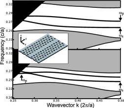
A silicon PhCWG studied here, made by removing a single row in a hexagonal lattice of holes - denoted as ”W1 PhCWG” - and its projected band structure can be seen in Fig. 1. This structure supports two tightly confined modes with small group velocities, as illustrated by the two bands within the band gap, with frequencies below the light line. The field distribution of these two modes, as computed through the plane wave expansion method,jj01oe is illustrated in Fig. 2. The strong subwavelength modal confinement of the high index contrast PhCWG leads to increased field intensities in the silicon gain media, permitting increased nonlinear interactions. In addition to increased field intensities from high index confinement, there is additional SRS enhancement from the small group velocities of the PhCWG propagating modes. Physically this enhancement originates from the effective long light-matter interaction times at small group velocities. Photon localization is observed at the band edge; the photon experiences multiple scattering processes and moves very slowly through the material structure. The guided bands of a 2D PhCWG can be designed to be as flat as desired () for slow-light behavior, and group velocities as low as to have been demonstrated.nys01prl ; gke05prl
In SRS for silicon an incident photon interacts with the LO and TO phonons. The strongest Stokes peak arises from the single first-order Raman-phonon at the center of the Brillouin zone. The generation of the Stokes photons can be understood classically as a third order nonlinear effect and this formalism has been used to model SRS in SOI waveguides, both in CW dhc03ol and pulsedcpo06jqe operation. It can be modeled in bulk materials as a degenerate four-wave-mixing problem involving the pump and Stokes beams. The important material parameter is the third order nonlinear Raman susceptibility, . For silicon, at resonance, is defined by the components = - = - (). An additional symmetry, imposed by the crystal point group (m3m for Si), is = 0.5. These components, and their permutations as defined by the crystal point group, define the SRS in a silicon crystal. For our purpose we shall consider scattering in silicon along the [] direction since practical devices are fabricated along this direction due to the favorable cleaving of silicon along this direction.
For bulk silicon, the evolution of the Stokes beam is defined by the following equation agr89ac
| (1) |
where . Here, and are unit vectors along the polarization directions of the pump and Stokes beams, respectively. Eq. (1) describes the gain of the Stokes intensity, . It shows an intrinsic dependence on the polarization and the phonon selection rules through , and the intensity of the pump beam by . The bulk solution also describes SRS in dielectric waveguides, where is averaged over the waveguide mode field distribution.
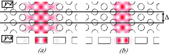
A PhCWG presents a very different field distribution than the bulk or dielectric waveguide case. As shown in the computed modal profiles of Fig. 2, the mode differs from that of a conventional channel waveguide in that it exhibits a periodic variation in the direction of propagation. We introduce the modal distribution of the pump and Stokes modes in a Bloch-Floquet formalism,
| (2) |
where is a mode index , is the mode wave-vector, is the modal distribution within a unit cell of the PhC, defined in Fig. 2, and obeys Bloch boundary condition . defines the length of the unit cell in the direction of propagation and for a W1 waveguide this equals the PhC lattice constant . To develop an equation that relates the evolution of the Stokes mode to the pump mode, we employ the Lorentz reciprocity theorem,booksl
| (3) |
This relates the unperturbed PhCWG modes of the pump or Stokes wavelengths, , to those of the nonlinearly induced fields. The envelopes of the fields are defined as
| (4a) | |||
| (4b) | |||
with the assumption that the change in the pump and Stokes field amplitudes, and respectively, over the length of the unit cell of the waveguide is very small (). Taking the fields as defined in Eq. (4), we derive the dependence of the Stokes amplitude on the longitudinal distance, ,
| (5) |
where is the mode power and . The integral in Eq. (5) is taken over the volume () of the unit cell of the PhCWG mode. Furthermore, the group velocity of the modes can expressed by the following equation booksl
| (6) |
With Eqs. (4) and (6), and by rewriting Eq. (5) in terms of the modes intensity, an equation for the intensity of the Stokes mode inside the PhCWG is obtained,
| (7) |
where
| (8) |
is the efffective susceptibility. Here, the effective area is defined as the average modal area across the volume ,
| (9) |
The final equation, Eq. (7), shows the explicit inverse dependence the Stokes mode amplification has on the group velocities of the pump and Stokes modes.
Table 1 shows the results of Eq. (7) as being applied to two different PhCWG schemes for SRS. The group velocities are calculated from the slope of the projected band structure. The first (Scheme 1) involves utilizing both the guided modes of the W1 waveguide; odd-parity is the pump mode and even-parity is the Stokes mode. The wavelength separation of the modes at the edge of the Brillioun zone is matched to the LO/TO frequency separation of the pump and Stokes beams (15.6 THz in Si th73prb ). The second (Scheme 2) utilizes a wide bandwidth PhCWG,dmv05prb in order for the Stokes and pump modes to exist both in the fundamental mode and below the light line. The arrows in Fig. 2 indicate the pump and Stokes frequency locations for both schemes.
| Scheme | |||
|---|---|---|---|
| 1 | 0.00017c | 0.0077c | 0.55 |
| 2 | 0.0041c | 0.24c | 2.02 |
From the results of Table 1, the Raman gain - proportional to - is enhanced by up to approximately (Scheme 1:66,000, Scheme 2:86) times compared to bulk Si based on a comparison of the respective group velocities. The results in Table 1 also show a value of the same order with a conventional SOI waveguide.cpo06jqe In addition, we note a reduction in in Scheme 1 as compared to Scheme 2, due to the lower modal overlap. However, the single mode (Scheme 2) operation has the disadvantage that only the Stokes mode, and not both modes, are at low group velocities for enhanced SRS.
The above results highlight the benefits of SRS enhancement through slow-light interactions in compact PhCWG schemes. This approach can be readily extended to include two photon and bulk free carrier absorption effects cpo06jqe which may limit the effective Raman gain in PhCWGs. These effects, in the experimental realization of silicon SRS amplification and lasing in slow-light PhCWGs, can be surmounted with pulsed-laser operation bj04oe or PIN diodes rlj05n to sweep the free-carriers.
In addition, we note recent theoreticalhry05prl and
experimentalvm06ol studies of PhCWGs, which show that slow group
velocity modes exhibit increased scattering losses. These losses are from coupling and intrinsic
(backscatter) reflection. Coupling into slow-light modes is currently the dominant loss
experimentally, although this can in principle be reduced through careful adiabatic coupling
jbs02pre between the PhCWGs and input/output channel bus waveguides. Moreover, with thorough attention
to fabrication disorder, reflection
losses in PhCWG are suggested to be comparable with index-guided waveguidesmlpov04apl .These
scattering losses can thus potentially be smaller than the enhanced SRS gain discussed, permitting
the possibility for compact silicon Raman amplifiers and lasers. We also note that, for the same
desired Raman gain, the device length is significantly reduced, by , allowing
compact integration for high-density photonic circuits.
This research was sponsored in part by DARPA, and the Columbia Initiatives in Science and Engineering in Nanophotonics. Both NCP and RMO would like to acknowledge financial support through AFOSR through contracts FA95500510428 and FA9550-04-C-0022, and NSF, Grant no. ECS-0523386. The authors also thank Steven G. Johnson for useful discussions on the low group velocity scattering. C. W. Wong’s email address is cww2104@columbia.edu.
References
- (1) R. L. Espinola, J. I. Dadap, R. M. Osgood, S. J. McNab, and Y. A. Vlasov, Opt. Express 12, 3713 (2004).
- (2) T. K. Liang and H. K. Tsang, Appl. Phys. Lett. 85, 3343 (2004).
- (3) Q. Xu, V. R. Almeida, and M. Lipson, Opt. Express 12, 4437 (2004).
- (4) O. Boyraz and B. Jalali, Opt. Express 12, 5269 (2004).
- (5) H. S. Rong, A. S. Liu, R. Jones, O. Cohen, D. Hak, R. Nicolaescu, A. Fang, and M. Paniccia, Nature 433, 292 (2005).
- (6) S. O. Konorov, D. A. Akimov, A. N. Naumov, A. B. Fedotov, R. B. Miles, J. W. Haus, and A. M. Zheltikov, JETP Lett. 75, 66 (2002).
- (7) X. Yang and C. W. Wong, Opt. Express 13, 4723 (2005).
- (8) L. Florescu and X. Zhang, Phys. Rev. E72, 016611 (2005).
- (9) S. G. Johnson and J. D. Joannopoulos, Opt. Express 8, 173 (2001).
- (10) M. Notomi, K. Yamada, A. Shinya, J. Takahashi, C. Takahashi, and I. Yokohama, Phys. Rev. Lett. 87, 253902 (2001).
- (11) H. Gersen, T. J. Karle, R. J. P. Engelen, W. Bogaerts, J. P. Korterik, N. F. van Hulst, T. F. Krauss, and L. Kuipers, Phys. Rev. Lett. 94, 073903 (2005).
- (12) G. P. Agrawal, Nonlinear Fiber Optics, (Academic, San Diego, 2001).
- (13) D. Dimitropoulos, B. Houshman, R. Claps, and B. Jalali, Opt. Lett. 28, 1954 (2003).
- (14) X. Chen, N. C. Panoiu, and R. M. Osgood, IEEE J. Quantum Electron. (to be published).
- (15) A. W. Snyder and J. D. Love, Optical Waveguide Theory, (London, U.K.: Chapman Hall, 1983).
- (16) P. A. Temple and C. E. Hathaway, Phys. Rev. B7, 3685 (1973).
- (17) E. Dulkeith, S. J. McNab, and Y. A. Vlasov, Phys. Rev. B72 115102 (2005).
- (18) S. Hughes, L. Ramunno, J F. Young, J. E. Sipe, Phys. Rev. Lett. 94, 033903 (2005).
- (19) Y. A. Vlasov and S. J. McNab, Opt. Lett. , (to be published); arXiv:physics/0504102.
- (20) S. G. Johnson, P. Bienstman, M. A. Skorobogatiy, M. Ibanescu, E. Lidorikis, and J. D. Joannopoulos, Phys. Rev. E66, 066608 (2002).
- (21) M. L. Povinelli, S. G. Johnson, E. Lidorikis, J. D. Joannopoulos, and M. Soljaĉić, Appl. Phys. Lett. 84, 3639 (2004).