Low crosstalk intersections of CCWs composed by mono-mode cavities
Abstract
Low crosstalk intersections formed by two crossing coupled cavity waveguides (CCWs), which are formed by series of mono-mode cavities in a two dimensional photonic crystal structure, are investigated. Although the individual cavities are mono-mode, the modes of the properly designed CCWs (which are called supermodes in this paper) may be dipole-like, and antisymmetry along the axis of the other perpendicular CCW, which ensures the low crosstalk of the intersections. According to the results of coupled mode analysis, we divide the intersections into two kinds based on the number of cavities of each CCW, and the transmission and crosstalk spectra of both kinds are numerically obtained using finite difference time domain (FDTD) method. The results show that crosstalk power is lower than dB. We also discuss the factors that affect the performance of the intersections.
pacs:
42.70.Qs, 42.79.GnI Introduction
Low crosstalk intersections of optical waveguides are key components in compact and high dense optical integrated circuits. Usually, the intersection of two crossing waveguides should be designed and optimized properly, or large crosstalk and reflection may be appear. For the intersections formed by two conventional planar waveguides, mode expander structures may be used to decrease crosstalk and reflection (intersection #0).cros0:jjap04 For the intersections of line defect waveguides in photonic crystals (PCs),PC:EYa ; PC:SJohn several designs have been proposed:cros1:StJohn ; cros2:SLan ; cros3:OL04 ; cros3:ptl05 Previously, the two crossing PC line defect waveguides are coupled to a common resonator (a point defect) (intersection #1), and the proper symmetry of the resonator’s mode ensures the low crosstalk between the two crossing waveguides.cros1:StJohn Subsequently, this idea is used to design the crossing of two modified planar waveguides (with cavities or cuts in them).cros1:StJohn ; cros0:jlt99 However, due to the single mode property of the resonator, only one operation frequency (the frequency can be tuned by the resonator) is demonstrated to be low crosstalk in Ref.cros1:StJohn, . Recently, S. Lan and H. Ishikawa proposed a broad bandwidth operation of line defect PC waveguide intersections by replacing the single resonator of intersection #1 with a coupled cavity structure (intersection #2).cros2:SLan Due to the wide broadband transmission band of the CCW,ccow:yariv ; ccow:prl broad bandwidth operation of low crosstalk intersection is numerically verified in a triangle lattice PC structure, cros2:SLan which is also valid for ultrashort (about 500-fs) pulse transmission for the broadband property. More recently, a new design and optimization of line defect PC waveguide crossing based on Wannier basis is investigated in a square lattice (intersection #3).cros3:OL04 ; cros3:ptl05 ; wannier The bandwidth of the optimized crossing is very high (), and crosstalk is very low (dB).cros3:ptl05
Apart from the line defect waveguide, another important kind of waveguide in PC is the coupled cavity waveguide (CCW).ccow:prl ; ccow:yariv Although many novel optical functional elements based on CCW structure have been proposed, such as the optical power splitter,ccow:spliter:apl ; ccow:spliter:apl03 band drop filter,ccow:banddrop nonlinear enhancement,ccow:nl:oe ; ccow:nl:prb optical delay linesccow:delay ; ccow:hop and optical bistable switching and limiting,ccow:ob:conti ; ccow:OL:conti the intersections of CCWs have not been investigated deeply. In fact, the intersection #2 of hybrid waveguides structure in Ref. cros2:SLan, is a design for two crossing CCWs.
Generally speaking, all the intersections mentioned above are all based on the orthogonality of the field pattern of one waveguide in the intersection area with respect to the other crossing waveguide. Therefore, the cavities of intersection #1 should be multi-pole mode, and a mono-pole mode is not suitable for low crosstalk intersection.cros1:StJohn ; cros2:SLan When a CCW is used, the intersection using the mono-pole mode of the cavity is also impossible.cros2:SLan
In this paper, we report a new mechanism of low crosstalk intersection of two CCWs, which are formed by sequences of mono-mode cavities in a square lattice PC structure. Although the individual cavities are mono-mode, the supermodes (result from the strong coupling between cavities) of the CCW may be dipole-like, which ensures the low crosstalk between the two intersecting CCWs, and the working frequencies can be tuned easily.
II Mode patterns of the supermodes
It’s reported that the eigenfrequency spectra of CCW structures follow into two different shapes:coupl12D ; ultrashort One is a continuous band and the other is a series of (the number of cavities) discrete modes.supermode:dwq And the shapes of the spectrum depend on the coupling strength between cavities.coupl12D ; ultrashort
For the continuous spectrum modes, the coupling between neighboring cavities is weak, and the tight binding theory gives a complete description.ccow:yariv ; ccow:prl While for the discrete modes, the coupling between neighboring cavities is strong, and we surprisingly find that a coupled mode theory may be used to predict the eigenfrequencies, mode profiles and as well as the quality factors of each supermodes.dwq:oc05 ; supermode:dwq
In the coupled mode theory, the electric field of the overall CCW is expressed by the superposition of the individual cavity modes with the superposition coefficients of arbitrary complex numbers of : supermode:dwq
| (1) |
Where is the total number of cavities, and and are the eigenfrequencies of an individual cavity and that of the coupled system. and are the eigenmodes of an individual cavity and that of the CCW. and are the distance between two neighboring cavities and the unit vector of the alignment direction of the cavities, respectively. Substituting Eq. (1) into the simplified Maxwell’s equation. Then operate the obtained equation using , one can obtain a group of coupled linear equations about the coefficients of . Solving the equation group, one obtain allowed supermodes for the CCW system. For the th () mode, the superposition coefficients are:
| (2) | |||||
| (3) |
Where is a normalized constant. For the details of the coupled mode theory, the readers are referred to Ref. supermode:dwq, .
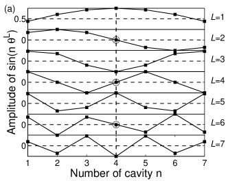
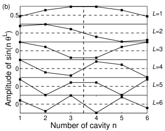
One of the most important results of the theory is the determination of the superposition coefficients of Eq.(2), which measure the contribution of each cavity to the th supermode. For the case of being an odd integer, i.e., with an integer, one can find that the amplitude of the central (th, ) cavity of the th supermodes are . Therefore, for the case of , . More importantly, the amplitudes of the th () cavity modes to both sides of the th cavity are antisymmetry, i.e, . For the other cases of , . Fig. 1(a) shows the values of for the case of . Clearly, for the th cavity, the coefficients of are all zero for , and more importantly, the overall distribution of the coefficients are antisymmetry about the center of the CCW (shown by the dashed line in Fig. 1).
For the case of being an even integer, i.e., with an integer, the coefficients of the central cavities (the th and th cavities) are not zero. However, the coefficients are also antisymmetry about the center of the structure for the cases of , and symmetry for the cases of . Fig. 1(b) shows the coefficients for the case of , and the symmetrical axis is shown by the dashed line.
From the analysis and theoretical results presented above, one can find that although the field pattern of an individual cavity is mono-pole symmetry, half of the supermodes of the CCW may be dipole-like, of which the mode patterns are antisymmetry about the center of CCW. If another CCW is set perpendicular to the CCW, and the intersection area is set at the center of the CCW, it is possible to achieve low crosstalk intersection for the for the supermodes of .
III Numerical results and discussion
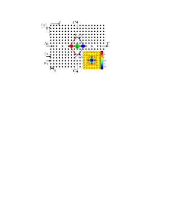
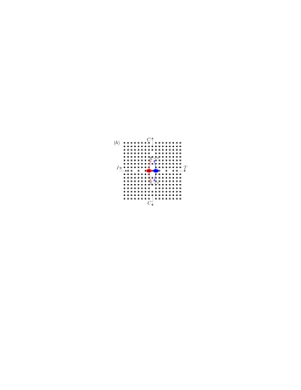
As an example of illustration, we design intersections of two CCWs in a frequently used square lattice PC structure, which is formed by dielectric cylinders in vacuum (), as shown in Fig.2. The refractive indexes of cylinders are , and the radii of the cylinders are , with the lattice constant. This PC structure opens a large band gap of for the TM polarization (electric field vector parallel to the axes of the cylinders). An individual cavity is fabricated by removing a cylinder completely. According to the above results of coupled mode theory, we divide the intersections into two types, as shown in Fig. 2, i.e,. type-A (Fig.2(a)) and type-B (Fig.2(b)).
For the type-A intersection, the numbers of cavities along both () and () directions are odd. Without loss of generality, we set and , respectively. And the two central cavities (the th along direction and the th along direction) are overlapped. The single cavity supports a monopole resonate state at the frequency of , as shown in the inset of Fig. 2(a). For the type-B intersection, the and are both even integers, as shown in Fig. 2(b).
According to the analysis in Ref.cros1:StJohn, and cros2:SLan, , the cavities, which support mono-modes only, are not suitable for low crosstalk operation. However, for the supermodes of the CCWs, low crosstalk is achieved successfully in the two structures of Fig. 2. Using the finite difference time domain (FDTD) method,fdtd:taflove the normalized spectrum of transmission and crosstalk are numerically derived. For the FDTD simulation, spatial grids are divided in a lattice constant , and perfect matched layers (PML) absorbing boundary conditions (ABC) are set around the structures.
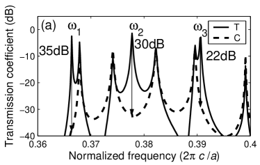
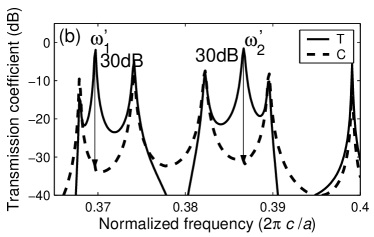
Fig. 3 shows the normalized transmission (solid lines) and crosstalk (dashed lines) power of the type-A intersection (shown in Fig.2(a)) when incident along direction (Fig.3(a)), and direction (Fig.3(b)), respectively. Clearly, for the direction incident, the three frequencies of , and transmit through the intersection with corresponding crosstalk of about dB, dB and dB, respectively. When the signal incident along direction, there are two frequencies of and transmit with a crosstalk ratios of both about dB.
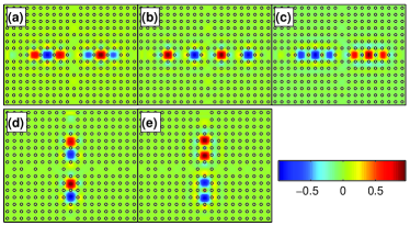
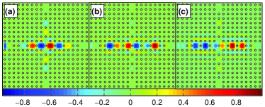
Fig. 4 shows the snapshots of the electric field distribution at steady state of the low crosstalk frequencies. Fig. 4(a), (b) and (c) correspond to the stable states of , and in Fig. 3(a). Fig. 4(d) and (e) correspond to the and in Fig. 3(b).
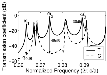
For the type-B intersection, similar results are obtained. The transmission and crosstalk spectra are shown in Fig. 5. For the three frequencies of , and , the crosstalk ratios are about dB, dB and dB, respectively. Fig. 6 (a), (b) and (c) show the electric field intensity distribution of the three frequencies of , and respectively.
From the results of coupled mode analysis, we have predicted that for the cavity number of and , there are frequencies of which the mode patterns satisfy the conditions of low crosstalk. The numerical results of Fig. 3, 4, 5 and 6 confirm our prediction. For the case of and , the number of low crosstalk frequencies are and . From the electric field distribution of Fig. 4 and Fig. 6, the low crosstalk mechanisms can be understood more clearly. One can see that near the intersection, there is a phase difference for the cavity modes to both sides of the crossing CCW, such as the 3rd and 5th cavities in Fig. 4 (a-c), and the 3rd and 4th cavities in Fig. 6. Therefore, the tunneling signals of them interfere destructively in the perpendicular CCWs, and this is the physical mechanism of low crosstalk.
According to the above discussion and numerical results, one can find that the number of cavity ( and ) affects the performance of the intersection greatly. Only the type-A and type-B structures can eliminate the crosstalk efficiently, i.e., the and must be both odd integers or both be even integers. If one of and is odd and the other is even, then low crosstalk is impossible for the mode symmetry of the supermodes. Another condition for the low crosstalk intersection is that the two CCWs must be overlap at the center and perpendicular to each other.
Although only a small number of and is discussed, one can straightly extend to the case of large values of ( and ). However, there is a maximum value for . Suppose the average linewidth of each mode is and the bandwidth of the CCW is about . The upper limit of is , and the maximum number of low crosstalk frequencies is ( means the integer part of a number). The bandwidth of the CCW can be tuned by changing the coupling of neighboring cavities.ccow:yariv ; ccow:prl And the linewidth of each mode can be tuned by the confinement of the cavities.supermode:dwq For the case of supermodes of CCW, the couple between cavities is much stronger than the case of continuous modes, therefore the bandwidth of is very large. For the structures demonstrated in this paper, the bandwidth (bandwidth to center frequency ratio ) is about , which is much larger than the bandwidth demonstrated before.cros2:SLan ; cros1:StJohn ; cros3:OL04 ; cros3:ptl05
In this paper, the reflection spectrum is not considered. Although the maximum normalized transmission power is only ( in Fig. 5), we belive that the reflection mainly originates from the coupling of the CCW and the incident source, but not from the existence of the intersection. The reflectance can be optimized using some tapered structure,taper:jlt ; taper:ol or using some novel optimization algorithm.cros3:ptl05 ; wannier
Finally, we want to point out that for the other eigenfrequencies (corresponding to the cases of for the case of or for the case of ), due to the symmetry of the mode profiles, the coupling of the two CCWs is strong. And this results in the supermodes split into more than one supermodes, and the crosstalk of them are all very high. In fact, the crosstalk are at the same level as the transmission power. Therefore, for these modes, the intersection structure performs just like a 1-to-3 power splitter, rather than a low crosstalk intersection.
IV Conclusions
In summary, we have investigated low crosstalk intersections of two CCWs that are composed by mono-mode cavities in a square lattice PC structures. The desired mode symmetry (orthogonal to the perpendicular CCW) is achieved by the combination of all the cavities but not a single cavity near the intersection. Our results show that for a cavity number of , there are (the integer part of ) frequencies are low crosstalk. We analyzed the mode profiles using a coupled mode theory, and obtained the transmission and crosstalk spectra using FDTD method. We also obtained the electric field distributions at stable states of the low crosstalk modes, from which we analyzed the physical mechanism of low crosstalk.
References
- (1) T. Fukazawa, T. Hirano, F. Ohno and T. Baba, Jpn. J. Appl. Phys. 43, 646 (2004).
- (2) E. Yablonovitch, Phys. Rev. Lett. 58, 2059 (1987).
- (3) S. John, Phys. Rev. Lett. 58, 2468 (1987).
- (4) S. G. Johnson, C. Manolatou, S. Fan, P. R. Villeneuve, J. D. Joannopoulos, and H. A. Haus, Opt. Lett. 23, 1855 (1998).
- (5) S. Lan, and H. Ishikawa, Opt. Lett. 27, 1567 (2002).
- (6) S.F. Mingaleev, M. Schillinger, D. Hermann and K. Busch, Opt. Lett. 29, 2858 (2004).
- (7) Y. Jiao, S.F. Mingaleev, M. Schillinger, D. A. B. Miller, S. Fan and K. Busch, IEEE Photon. Tech. Lett. 17, 1875 (2005).
- (8) K. Busch, S. F. Mingaleev, A. Garcia-Martin, M. Schillinger, and D. Hermann, J. Phys., Condens. Matter 15 R1233 (2003).
- (9) C. Manolatou, S. G. Johnson, S. H. Fan, P. R. Villeneuve, H. A. Haus, and J. D. Joannopoulos, J. Ligtwave Tech. 17, 1682 (1999).
- (10) A. Yariv, Y. Xu, R. K. Lee, and A. Scherer, Opt. Lett. 24, 711 (1999).
- (11) M. Bayindir, B. Temelkuran, and E. Ozbay, Phys. Rev. Lett. 84, 2140 (2000).
- (12) M. Bayindir, B. Temelkuran, and E. Ozbay, Appl. Phys. Lett. 77, 3902 (2000).
- (13) A. Martinez, F. Cuesta, and A. Griol et al, Appl. Phys. Lett. 83, 3033 (2003).
- (14) M. Bayindir and E. Ozbay, Opt. Express 10, 1279 (2002), http://www.opticsexpress.org/.
- (15) Y. Chen and S. Blair, Opt. Express 12, 3353 (2004).
- (16) D. G. Gusev, I. V. Soboleva, M. G. Martemyanov, T. V. Dolgova, A. A. Fedyanin, and O. A. Aktsipetrov, Phys. Rev. B 68, 23303 (2003).
- (17) M. Bayindir, B. Temelkuran, and E. Ozbay, Phys. Rev. B 61, R11855 (2000).
- (18) Y. Sugimoto, S. Lan, S. Nishikawa, N. Ikeda,H. Ishikawa and K. Asakawa, Appl. Phys. Lett. 81, 1946 (2002).
- (19) W. Q. Ding, L. X. Chen, and S. T. Liu, Opt. Commun. 246, 147 (2005).
- (20) W. Q. Ding, L. X. Chen, and S. T. Liu, Chin. Phys. Lett. 21, 1539.
- (21) W. Q. Ding, L. X. Chen and S. T. Liu, arXiv.org: physics/0508127.
- (22) S. Lan, S. Nishikawa, Y. Sugimoto, N. Ikeda, K. Asakawa, and H. Ishikawa, Phys. Rev. B 65, 165208 (2002).
- (23) S. Lan, S. Nishikawa, H. Ishikawa and O. Wada, J. Appl. Phys. 90, 4321 (2001).
- (24) W. Q. Ding, L. X. Chen and S. T. Liu, Opt. Commun. 248, 479 (2005).
- (25) A. Taflove, Computatinal Electrodynamics: The Finite-Difference Time-Domain Method (Norwood, MA: Artech House).
- (26) A. Mekis and J. D. Joannopoulos, J. Lightwave Tech. 19, 861 (2001).
- (27) A. Talneau, Ph. Lalanne, M. Agio, C. M. Soukoulis, Opt. Lett. 27, 1522 (2002).