Preprint of:
D. K. Gramotnev, S. J. Goodman and T. A. Nieminen
“Grazing-angle scattering of electromagnetic waves in
gratings with varying mean parameters: grating eigenmodes”
Journal of Modern Optics 51, 379–397 (2004)
Grazing-angle scattering of electromagnetic waves in gratings with varying mean parameters: grating eigenmodes
D. K. Gramotnev1, S. J. Goodman1 and T. A. Nieminen2
1Applied Optics Program, School of Physical and Chemical Sciences, Queensland University of Technology, GPO Box 2434, Brisbane, Queensland 4001, Australia; e-mail: d.gramotnev@qut.edu.au
2Centre for Biophotonics and Laser Science, Department of Physics, The University of Queensland, St Lucia, Queensland 4072, Australia
Abstract
A highly unusual pattern of strong multiple resonances for bulk electromagnetic waves is predicted and analysed numerically in thick periodic holographic gratings in a slab with the mean permittivity that is larger than that of the surrounding media. This pattern is shown to exist in the geometry of grazing-angle scattering (GAS), that is when the scattered wave ( diffracted order) in the slab propagates almost parallel to the slab (grating) boundaries. The predicted resonances are demonstrated to be unrelated to resonant generation of the conventional guided modes of the slab. Their physical explanation is associated with resonant generation of a completely new type of eigenmodes in a thick slab with a periodic grating. These new slab eigenmodes are generically related to the grating; they do not exist if the grating amplitude is zero. The field structure of these eigenmodes and their dependence on structural and wave parameters is analysed. The results are extended to the case of GAS of guided modes in a slab with a periodic groove array of small corrugation amplitude and small variations in the mean thickness of the slab at the array boundaries.
1 Introduction
Grazing-angle scattering (GAS) is a strongly resonant type of scattering in uniform strip-like slanted wide periodic gratings [1 4]. It is realized when the scattered wave ( diffracted order for first-order GAS [1,2,4], or order for second-order GAS [3]) propagates almost parallel to the front grating boundary, that is at a grazing angle to this boundary. Thus, GAS is intermediate between extremely asymmetrical scattering (EAS) (which occurs when the scattered wave propagates parallel to the grating boundaries [5 8]) and conventional Bragg scattering in reflecting or transmitting gratings (where the scattered wave propagates at a significant angle with respect to the grating boundaries).
The main distinctive feature of GAS is a strong resonant increase in amplitudes of the scattered wave ( order [1,2,4] or order [3]) and incident wave (zero order) inside a wide slanted grating at a resonant (grazing) angle of scattering. A grating is regarded to be wide if its width is larger than a determined critical width [9,10]. In narrow gratings (i.e. for ) the GAS resonance does not exist [1 3].
One of the most unexpected features of the GAS resonance is that it strongly increases in height and sharpness with increasing grating amplitude and/or grating width [1 4]. A physical explanation for this resonant behaviour with respect to angle of scattering has been related to resonant generation of a special new type of grating eigenmodes that are guided by the grating in the absence of any conventional guiding effect in the structure [2,3].
Another interesting and practically important feature of EAS and GAS is their unusual and strong sensitivity to small step-like variations of mean structural parameters (e.g. mean dielectric permittivity) at the grating boundaries [4,11]. This is because one of the main physical mechanisms resulting in EAS and GAS is diffractional divergence of the scattered wave (similar to divergence of a laser beam of finite aperture) [1,6,7,9 11]. Since diffractional divergence can be strongly affected by small variations in mean structural parameters [12], EAS and GAS appear to be highly sensitive to such variations [4,11]. The expected consequences of such a sensitivity for the experimental observation and application of EAS and GAS have been discussed in [4,11].
In particular, Gramotnev et al. [4] investigated GAS in a symmetric structure with a holographic grating in a slab surrounded by identical media with the permittivities that are smaller than the mean permittivity in the grating region (slab). However, only very small variations in the mean permittivity at the grating boundaries were considered, such that the angle of total internal reflection for the wave in the slab is larger than the angle of scattering corresponding to the GAS resonance [4]. As a result, the tolerance of GAS to small variations in the mean permittivity has been determined [4].
In this paper, we shall demonstrate the existence of new, highly unusual strong multiple resonances in a slanted holographic grating in the geometry of GAS in the presence of the conventional guiding effect, that is when the mean permittivity in the grating region (slab) is larger than outside it. These multiple resonances will be shown to exist only in sufficiently wide gratings (with ) and for relatively large variations in the mean permittivity at the grating boundaries, such that the angle of total reflection for the wave in the slab is smaller than the GAS resonant angle.
A new type of electromagnetic mode guided by a slab with a periodic holographic grating will be discovered theoretically. The field structure and propagation parameters of these modes will be investigated. The multiple GAS resonances in the considered structure will be explained by resonant generation of the predicted new slab eigenmodes. The analysis for bulk electromagnetic waves will be carried out by means of the rigorous theory of GAS and EAS [2,8], based on the enhanced T-matrix algorithm [13,14]. The extension of the theory to the case of GAS of optical modes guided by a slab with a corrugated boundary will also be discussed.
2 Structure and methods of analysis
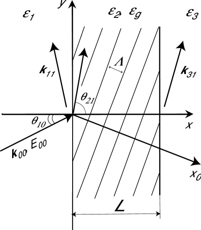
The structure that is under investigation in this paper is similar to that analysed in [4]. Namely, we consider GAS of bulk transverse electric (TE) electromagnetic waves in a holographic grating in a slab of thickness between two media of constant dielectric permittivities and (figure 1):
| (1) |
where the coordinate system is shown in figure 1, is the mean dielectric permittivity in the grating, is the grating amplitude, is the reciprocal lattice vector that is parallel to the axis, , and is the grating period. The grating is assumed to be infinite along the and axes, and the dissipation is absent, that is are real and positive. The step-like variations of the mean dielectric permittivity at the front and rear grating boundaries are given by and . In this paper we shall mainly assume that , that is, the grating region represents a planar waveguide capable of guiding electromagnetic modes. A plane bulk TE electromagnetic wave (with the amplitude and wave vector in medium 1 (see figure 1) is incident on to the grating at an angle that is measured anticlockwise from the positive direction of the axis to the vector (figure 1). The non-conical geometry of scattering is considered. The angle of scattering in the grating region is supposed to be close to , that is, the scattered wave (the order) with the wave vector and the -dependent amplitude propagates almost parallel to the grating boundaries (the geometry of GAS) (figure 1).
As mentioned above, Gramotnev et al. [4] have investigated GAS in the same structure, but with small variations in the mean permittivity at the grating boundaries, such that the angle of total internal reflection for a wave in the slab was larger than the angle of scattering corresponding to the GAS resonance in the same grating but with zero variations in the mean permittivity [4]. This condition restricted the analysis to the case of only very small values of . This was important for understanding the tolerances of GAS and its application possibilities for design of new sensors and measurement techniques. At the same time, in the next section we demonstrate that the case of larger variations in the mean permittivity (when the angle of total reflection is larger than the resonant angle for GAS) is even more interesting, since it results in a discovery of a number of much stronger additional resonances and a new type of eigenmodes of a slab with a slanted holographic grating.
3 Numerical results
As mentioned above, Gamotnev et al. [4] determined the tolerance of GAS to small symmetric variations in the mean dielectric permittivity at the grating boundaries (), such that the angle of total internal reflection for a wave in the slab was larger than or equal to the GAS resonant angle [1,2]. Figures 2 and 3 present the dependences of amplitudes of the order (scattered wave) on the angle of scattering in the middle of the grating (solid curves) and at the front and rear boundaries (dotted curves) in the opposite case, that is for larger symmetric variations of the mean permittivity (), such that . The specific values of are chosen so that , and we have a sufficiently broad range of angles between and . Note that for the considered structures the scattered wave amplitudes at the front and rear grating boundaries are almost identical, and thus they are represented by only one dotted curve in each of the subplots. The grating (or slab) width is kept the same for all the subplots: m (the other structural and wave parameters are presented in the figure captions). The Bragg condition is assumed to be satisfied precisely for all angles of scattering: that is, we investigate only the effect of the angle of scattering on the pattern of GAS, excluding the effect of frequency and/or angular detunings of the Bragg condition.
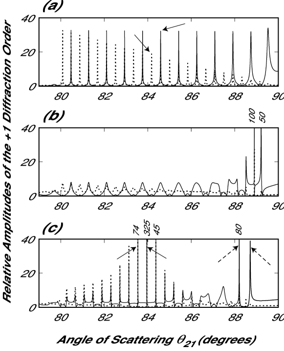
Depending on the grating amplitude , the considered grating width m can be smaller or larger than the critical grating width . For example, for figure 2 (a), the grating amplitude , which corresponds to m [9]. This is noticeably larger than m. Therefore, the pattern presented in figure 2 (a) is typical for narrow gratings. It will be discussed in detail below. At this stage we shall only mention that the presented resonances (figure 2(a)) are not related to GAS, since GAS resonances do not exist in narrow gratings [1,2] (for more detail see below).
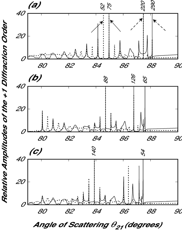
Figures 2 (b) and (c) and 3 (a)–(c) present the typical dependences of scattered wave amplitudes in the middle of the grating (slab) and at its boundaries in wide gratings of the same actual width (m), but with larger grating amplitudes that make the critical grating width smaller, that is . The specific values of for each of the subplots are presented in the figure captions.
It can be seen that increasing the grating amplitude so that the grating width becomes just larger than (figure 2 (b)) results in the appearance of extremely high and sharp resonances just below which is the GAS resonant angle in the same structure, but with zero variations in the mean permittivity (for figure 2 (b), [1,2]). The rightmost resonant maximum in figure 2 (b) (i.e. in the structure with ) occurs almost exactly at . This statement is also correct for all other subplots (figures 2 (c) and 3 (a) (c)). Note that, as mentioned in [1,2], decreases with increasing grating amplitude. Therefore, the rightmost maxima in figures 2 (b) and (d) and 3 (a) (c) shift to the left with increasing .
Though the rightmost maxima in figures 2 (b) and (d) and 3 (a) (c) occur at , these resonances are much stronger and sharper than those in the same structures, but with zero variations in the mean permittivity. For example, in figure 3 (a), the rightmost maximum goes up to about , while in the same structure with it is only about . Thus, symmetric negative variations in the mean permittivity at the grating boundaries may result in an extremely strong increase in the GAS resonance at . One of the physical reasons for this effect is that, if , then the scattered wave at experiences total internal reflection from the slab interfaces. This leads to a substantial reduction in the energy losses from the grating, since the diffracted orders outside the grating become non-propagating (evanescent) waves. As a result, the scattered wave amplitude inside the grating may significantly increase.
In addition, if , then on the left of the resonance at there appear a number of other extremely strong and sharp (often, even sharper and stronger) resonances at resonant angles within the angle range (figures 2 (b) and (c) and 3 (a) (c)). As the grating amplitude increases, so that the grating width becomes just larger than , a bunch of these additional strong resonances appears just below the angle (figure 2 (b)). If the grating amplitude is increased (so that becomes increasingly larger than ), this bunch of maxima ‘shifts’ from towards (figure 2 (c)). The word ‘shifts’ is put in quotes because the discussed resonant maxima do not actually move along the horizontal axis with increasing . Changing results in only insignificant variations in the values of the resonant angles . However, the height of these resonances can change very strongly. For example, the sharp resonances within the range between approximately and in figure 2 (c) simply increase when the grating amplitude increases to .
When the first bunch of resonances ‘moves away’ from the angle (for a sufficiently large ) another bunch starts to appear near this angle (figure 2 (c)). This bunch also ‘shifts’ to the left towards with further increasing , and so on (figures 3 (a) (c)). At larger grating amplitudes, this process becomes less obvious, since the angular distance between the bunches and the number of resonances in a bunch decreases (figures 3 (a) (c)). Note also that the number of resonances in a bunch increases as the bunch ‘shifts’ towards .
The resonances in the bunches are spaced (on the angular scale) approximately periodically, especially for smaller grating amplitudes (figures 2 (c) and 3 (a)). The period is approximately the same for all the bunches, but resonances in each successive bunch occur approximately between the resonances in the previous bunch (figures 2 (b) and (c) and 3 (a) (c)). Increasing grating width results in a rapid increase in the total number of the resonances, that is, the angular distance between them is reduced. Increasing grating width also results in increasing typical height and sharpness of the resonances. On the other hand, changing values of has only a limited effect on the values of and the typical angular distance between the resonances. At the same time, varying the mean permittivity in the grating can substantially change (increase or decrease) the height and sharpness of the resonances (optimization of the values of will be discussed below). The number of the GAS resonances is also increased with increasing , because of the increasing range of angles between and .
If an asymmetric structure is considered (with , and ), then some of the GAS resonances may strongly increase, while others may be reduced, depending on particular values of the variations of the mean permittivity. At the same time, the angular position of the resonances depends on and only very weakly. In this case, strong GAS resonances can be observed within the range of angles max(), where and are the angles of total internal reflection from the front and rear boundaries of the grating (slab). Below this range, strong GAS resonances cannot exist, because in this case the scattered wave either in front (if ) or behind (if ) the grating becomes a propagating wave travelling away from the grating. This wave is associated with substantial energy losses from the grating, resulting in a deterioration of any strong resonance of scattering. This is also the reason why the described pattern of strong multiple GAS resonances (figures 2 (b) and (c) and 3 (a) (c)) cannot exist if at least one of the variations or is zero, positive or sufficiently small negative that the angle of total reflection from the corresponding slab interface is larger than [4].
4 Physical reasons: conventional guided modes or not?
It is obvious that the structure with (i.e. the mean permittivity in the slab is higher than that of the surrounding media) is capable of supporting the conventional guided modes. Therefore, a reasonable question naturally arises from the above consideration: are all, or at least some, of the predicted strong multiple GAS resonances in figures 2 (b) and (c) and 3 (a) (c) related to generation of the conventional guided modes of the slab? To answer this question, let us consider physically the conditions for effective generation of conventional guided modes in a slab with a holographic grating. A conventional guided mode can be represented by a bulk wave travelling in the slab and experiencing total internal reflection from its boundaries [15]. An angle , at which this bulk wave should propagate in the slab to form a particular slab mode, is determined by the dispersion relationship for the guided mode and the fact that the wave vector of this guided mode must be equal to the tangential (to the slab) component of the wave vector of the bulk wave in the slab [15]. Thus, , where is the magnitude of the wave vector of the considered conventional slab mode. Determining q from the dispersion relationship for the slab modes, we can easily see that each of the resonant angles corresponding to the sharp resonances within the range from to in figure 2 (c) lies almost exactly in the middle between two neighbouring values of . This clearly suggests that the above-mentioned GAS resonances cannot be associated with generation of the conventional slab modes.
On the other hand, the same consideration demonstrates that all the resonances in figure 2 (a) occur at the angles corresponding to the conventional slab modes in the considered structure. This suggests that, if the grating amplitude and/or grating width are sufficiently small, we indeed have resonant generation of the conventional slab modes in the structure (the maxima of the solid curve in figure 2 (a) correspond to symmetric TE slab modes, while the maxima of the dotted curve correspond to antisymmetric TE slab modes).
This is because a bulk wave in a slab (reflecting from the slab interfaces) forms a guided mode only if it experiences at least several reflections from the slab interfaces, otherwise it is just a bulk wave travelling from one slab boundary to another with no restrictions on the angle of propagation. On the other hand, scattering in the grating is characterized by a critical length of the grating (along the axis), , within which the steady-state regime of scattering is reached [7,16]. Here, is the relaxation time for a particular resonance [7,16], and is the speed of light in vacuum. Resonant generation of the conventional modes guided by a slab with a holographic grating occurs (figure 2 (a)) when lc for the corresponding resonance is noticeably larger than the distance that the bulk wave in the slab travels between two successive reflections. For example, for figure 2 (a), the analysis developed in [16] gives cm, while ranges from about 0.02 cm to 0.2 cm for the angles within the range between and .
If the grating width is increased, then increases proportionally. If , we rather have generation of a bulk wave in the grating region, and the successive reflections do not effectively restrict angles of scattering so that they can vary in a wide range, not necessarily corresponding to a conventional guided mode. This may also happen when the grating amplitude is increased and constant. In this case, is constant, but the efficiency of scattering is increased, resulting in a smaller critical grating length . This eventually leads to the same inequality . Therefore, the resonances due to generation of the conventional guided slab modes must become broader with increasing grating width and/or grating amplitude . This is what can clearly be seen from the comparison of the curves in figure 2 (a) with the curves in figure 2 (b) at angles . (A very similar effect occurs when the grating width is increased and constant).
Note that increasing angle of scattering results in increasing . Therefore, the maxima in figures 2 (a) and (b) due to the conventional slab modes increase in width with increasing . Eventually, for angles of scattering in figure 2 (b), lc becomes approximately the same as and the whole pattern of scattering drastically changes; for angles , the resonances due to the conventional guided modes disappear, being replaced by strong GAS resonances at ‘wrong’ resonant angles of scattering (figure 2 (b)).
However, it is important to note that, for strong GAS resonances, the relaxation time is large, and becomes again larger than . This is also quite clear from the fact that, in the GAS resonances, the selectivity of scattering with respect to angle is extremely high (figures 2 (b) and (c) and 3 (a) (c)), which can only be achieved if the effect of the rear slab boundary on scattering is significant (recall that we do not consider the angular response of the grating, and the Bragg condition is satisfied precisely for all scattering angles). That is, the bulk scattered wave in the grating should be able to travel many times across the grating, before the steady state is finally reached. This implies that for the GAS resonances the condition must again be satisfied.
As a result of this consideration, we can draw an important conclusion that strong GAS resonances in a slab with a slanted holographic grating have nothing to do with the resonant generation of the conventional slab modes. All the predicted GAS resonances represent a new phenomenon in a slab with a slanted grating.
This conclusion can be made even more convincing if we investigate the angular dependences of the scattered wave amplitude in the grating at angles . Indeed, if we extend the curves in figure 2 (a) to angles , they will be almost exactly symmetric with respect to . This is well expected, since a conventional guided slab mode can be represented by a bulk wave successively reflecting from the slab interfaces. Therefore, scattering at two angles and can equally result in generation of the same mode guided by the slab.
On the contrary, no GAS resonances can be observed at angles . This is similar to what was predicted for gratings with zero variations in the mean permittivity at the boundaries [1,2]. That is, unlike scattering into conventional guided modes of a slab with a holographic grating, the pattern of GAS is completely asymmetric with respect to the scattering angle . This once again emphasizes strong differences between the resonances of scattering due to generation of conventional slab modes (figure 2 (a)) and GAS resonances (figures 2 (b) and (c) and 3 (a) (c)).
5 New grating eigenmodes
In the previous section, we have clearly demonstrated that the predicted multiple-GAS resonances have nothing to do with generation of the conventional guided modes in the slab (grating region). However, this still does not give us a physical explanation for these new resonances. On the other hand, it is well known that any strong resonance is associated with some kind of eigenoscillations or eigenmodes in the structure. Therefore, the described strong GAS resonances must also be related to generation of some type of eigenmodes in the considered structure with a grating in a slab. At the same time, as demonstrated in the above section, these are not conventional guided slab modes that are responsible for the predicted GAS resonances. Therefore, a completely new type of eigenmode must be generated in the slab by means of an incident wave. These are grating eigenmodes that were first predicted in [2,3]. However, in [2,3], grating eigenmodes were considered only in the absence of the conventional guiding effect in the structure. Here, we demonstrate that the presence of the conventional guiding effect, that is when the mean permittivity in the grating region is larger than the permittivity outside the grating, results in drastic changes in the pattern of GAS and therefore of the structure of the grating eigenmodes.
Indeed, figures 2 and 3 clearly demonstrate that a large number of very sharp and strong resonances can exist in a grating with . These resonances appear to be much higher than those in the case when [2] (figures 2 and 3). The typical number of these sharp and strong resonances rapidly increases with increasing grating width and/or mean permittivity in the grating (see above), so does the number of different grating eigenmodes in the structure.
It is also clear that the discussed grating eigenmodes in a slab are not true eigenmodes, because they weakly leak into the regions outside the grating (see also [2,3]). Indeed, these modes are resonantly generated by an incident bulk wave, and coupling between guided and bulk waves can occur only if the guided waves (grating eigenmodes) leak into the surrounding media. At the same time, since the corresponding GAS resonances are extremely high (up to hundreds (figures 2 and 3) or even thousands (see below) of the amplitude of the incident wave at the front grating boundary), the leakage of the grating eigenmodes must be very weak (weak coupling between the incident wave and grating eigenmodes). Therefore, these eigenmodes should be able to propagate long distances along the grating (in the absence of the incident wave at the front boundary), before their amplitudes are significantly decreased owing to leakage. These typical distances can approximately be determined by the relaxation time for the corresponding GAS resonances. The larger the relaxation time, the stronger is the resonance and the longer is the distance that the corresponding eigenmode can propagate without noticeable decay (due to leakage) along the grating. The relaxation time can be determined using the method based on the Fourier analysis of the incident pulse [16]. As mentioned above, during the relaxation time , the scattered wave propagates the distance along the grating, which should approximately be equal to the distance that the corresponding eigenmode can propagate along the grating in the absence of the incident wave. For example, the results of [16] suggest that a resonance of about high should usually correspond to an value of about several tens of centimetres.
It is important to understand that the predicted new eigenmodes of a guiding slab with a grating are generically associated with scattering. They do not exist if there is no grating in the slab. This is one of their major differences from the conventional slab modes. Grating eigenmodes exist only at sufficiently large grating amplitudes and/or widths of the grating (see the previous section and [2,3]). If the grating amplitude and/or grating width are small (so that ), GAS resonances and the corresponding eigenmodes do not exist and are replaced by the resonances caused by generation of the conventional guided slab modes (figure 2 (a)).

The typical dependences of the relative amplitudes and of the scattered and incident waves, respectively, inside the grating are presented in figure 4 for several strong resonances that are indicated by the solid arrows in figures 2 (a), 2 (c) and 3 (a) (other diffracted orders have negligible amplitudes at the considered grating amplitudes). Since these resonances are very high, the field structure in the grating at the corresponding resonant angles of scattering should approximately be the same as that of the corresponding eigenmodes. Indeed, in this case, the modes are only weakly leaking from the grating (slab), and the amplitude of the incident wave at the front grating boundary is much smaller than the amplitudes of the scattered and incident waves in the grating (figure 4). Therefore, the resultant sum of the fields corresponding to the eigenmode and to the incident wave will hardly be different from the field structure of the eigenmode alone. Note that this is relevant to any sufficiently sharp resonance, irrespective of whether this resonance is due to the conventional guided slab modes (figure 2 (a)), or new grating eigenmodes (figures 2 (b) and (c) and 3 (a) (c)). Therefore, the dependences presented in figures 4 (a) (c) with a good approximation represent the field structure of the corresponding eigenmodes (conventional and new).
Thus the dotted and solid curves in figure 4 (a) approximately represent the field structure in symmetric and antisymmetric conventional guided modes of the slab, corresponding to the resonances indicated by the solid arrows in figure 2 (a). The broken curve represents the dependences of the incident wave amplitude for both the considered resonances. However, the incident wave in the grating is not a part of the conventional slab eigenmode. Indeed, the incident wave amplitude in the grating can be made arbitrarily small compared with the amplitude of the scattered wave by reducing the grating amplitude. Therefore, conventional slab modes can obviously exist in a slab with no grating.
The situation with the grating eigenmodes is completely different. Firstly, grating eigenmodes are usually generated at different angles of scattering (see section 3). Secondly, grating eigenmodes of a slab are intrinsically related to scattering and cannot exist in the absence of the grating. Thirdly, because they are generically related to scattering, the 0 diffracted order (incident wave) in the grating is an inseparable part of the grating eigenmodes (also [2,3]). The amplitude of the 0 diffracted order in the grating can never be made arbitrarily small compared with the amplitude of the scattered wave ( order) without destroying the eigenmode (and the corresponding GAS resonance). Thus the field structure in a grating eigenmode is given not only by the scattered wave but rather by a superposition of the fields of all diffracted orders involved (see also [2,3]).
Figures 4 (b) and (c) present the typical dependences of the scattered and incident wave amplitudes in the grating for the several resonances indicated by the solid arrow in figures 2 (c) and 3 (a) (corresponding to generation of grating eigenmodes in the slab). It can be seen that these dependences are significantly different from those in figure 4 (a). In particular, unlike figure 4 (a), the amplitudes of the incident wave in figures 4 (b) and (c) are much larger than , its amplitude at the front grating boundary. As mentioned above, there is no way that we could make them negligible compared with the amplitude of the scattered wave, without destroying the corresponding resonances and, hence, the grating eigenmodes.
Comparison of figure 4 (a) with figures 4 (b) and (c) suggests that the scattered wave amplitudes inside the grating experience strong oscillations (as a function of ) for both conventional slab modes and grating eigenmodes. However, the dependences corresponding to grating eigenmodes display beat-like modulation of these oscillations with one or more waists (see the solid and dotted curves in figures 4 (b) and (c)). The number of these waists is determined by the bunch of maxima (figures 2 (b) and (c) and 3 (a) (c)) that the considered resonance belongs to. For example, the dependences of the scattered wave amplitude in figure 4 (b) show only one waist if the corresponding resonances belong to the first bunch of maxima (figure 2 (c)). The two waists are displayed by the solid and dotted curves in figure 4 (c), because the corresponding resonances belong to the second bunch of maxima (figure 3 (a)), etc.
The typical number of oscillations of the dependences of the scattered wave amplitude in the grating increases with decreasing resonant angle of scattering (i.e. with increasing grazing angle between and the grating boundaries). For example, if we shift from the resonance in figure 2 (c), indicated by the right solid arrow, to the neighbouring resonance indicated by the left solid arrow, the number of oscillations of the dependencies of the scattered wave amplitudes is increased by one (compare the dotted and solid curves in figure 4 (b)). This is very similar to what occurs for the conventional guided modes (figure 4 (a)).

Thus, if we consider the GAS resonance at (the largest possible resonant angle), the number of oscillations of the dependence of the scattered wave amplitude in the grating is reduced to one. This is demonstrated by figures 5 (a) and (c) that are plotted for the rightmost resonances in figures 2 (c) and 3 (a), respectively. The number of bumps on the solid curves in figures 5 (a) and (c) (two for figure 5 (a) and four for figure 5 (c)) corresponds to the bunch number that these resonances belong to (these bumps correspond to the ‘waists’ in the case of the large number of oscillations (figures 4 (b) and (c)).
Note also that the dependences in figures 5 (a) and (c) are similar to those obtained for grating eigenmodes in the case of zero variations of the mean permittivity at the grating boundaries [1,2]. The main difference from the case when [1,2] is that the dependencies of the scattered wave amplitudes in figures 5 (a) and (c) are not close to zero at the grating boundaries. If this were the case for a grating with constant mean permittivity, there would have been substantial energy losses from the grating because propagating scattered waves outside the grating carry the energy away from the grating. As a result, the corresponding grating eigenmodes would have quickly decayed owing to strong leakage. This is the reason why only a limited number of grating eigenmodes can exist in the gratings with constant mean permittivity, that is only those for which the scattered wave amplitude is close to zero at the grating boundaries [1,2].
In the presence of the conventional guiding effect in the grating (i.e. when ), the situation is significantly different. In the scattering angle range , the scattered waves outside the grating are non-propagating (evanescent) waves that do not carry energy away from the grating. Therefore, the leakage of the grating eigenmodes can occur only as a result of the 0 diffracted order (incident wave) at the rear boundary, which has an amplitude that is much smaller than the amplitudes of the incident and scattered waves in the grating (recall that other diffracted orders in the considered gratings have even smaller amplitudes). Therefore, the leakage is weak in the whole mentioned range of angles . As a result, a number of new (additional), weakly leaking grating eigenmodes with different field structures (presented, for example, in figures 4 (b) and (c) and 5 (b) and (d)) can exist in a slab with a holographic grating.
As mentioned above, variations in the mean permittivity in the grating region (in the slab) result in only limited variations in the angles corresponding to strong GAS resonances in figures 2 (b) and (c) and 3 (a) (c). At the same time, these variations may have a drastic effect on height and sharpness of the GAS resonances. This means that changing the mean permittivity in the grating region (slab) must have a substantial impact on the leakage of the corresponding grating eigenmodes.

It is not difficult to optimize the variations in the mean permittivity, , so that a particular GAS resonance becomes as high as possible for a given grating amplitude. To do this, we plot the dependence of the scattered wave amplitude (e.g. in the middle of the grating) on the scattering angle and record the maximal value of this amplitude, corresponding to a particular resonance for a given . Then, change and repeat the above procedure. As a result, we obtain the dependence of maximal values of the scattered wave amplitude, corresponding to a particular resonance, on . For example, the solid curve in figure 6 (a) represents such a dependence for the maximal scattered wave amplitude in the middle of the grating for the first GAS resonance (i.e. at ). The grating parameters are , m, and m. The broken curve in this figure gives the corresponding values of the scattered wave amplitudes at the front and rear grating boundaries. Note that, since weakly depends on , its values are slightly different for different points on the curves in figure 6 (a). Thus, it is clear that variations in the mean permittivity in the grating region (compared with the regions outside the grating) may lead to a very substantial increase of the height of the GAS resonance (figure 6 (a)).
The predicted strong resonances at optimal values of ( in figure 6 (a)) obviously result in the generation of very weakly leaking grating eigenmodes. Thus, optimization of to the strongest GAS resonance automatically means optimization of the corresponding eigenmode to the minimal losses due to leakage. According to the results of the rigorous analysis of nonsteady-state EAS [16], the typical propagation distance for such an eigenmode is expected to be around several tens of metres. However, the exact analysis of this question will require more consistent application of the methods developed in [16] to GAS in the considered structure (which is beyond the scope of the current paper).
The dependences of the relative scattered wave amplitudes on angle of scattering at the optimized value of ( (figure 6 (a)) are presented in figure 6 (b) by the solid curve (in the middle of the grating) and broken curve (at the grating boundaries). It can be seen that the angular width of the optimized resonance is about . It is quite clear that such a resonance can hardly be achieved in practice, owing to the excessively long relaxation time. Therefore, its major importance is in the demonstration of the existence of new, very weakly leaking grating eigenmodes. In the end, these eigenmodes can be generated by the same means as conventional slab modes (but not necessarily by means of GAS).
The dependences of the amplitudes of the incident (dotted curve) and scattered (solid curve) waves in the optimized grating eigenmode (i.e. corresponding to the resonance in figure 6 (b): and ) are presented in figure 6 (c). It can again be seen that, unlike the eigenmodes in gratings with zero variations in the mean permittivity [1 3], the amplitudes of the scattered wave at the grating boundaries are strongly non-zero. As has been indicated, this does not result in any energy losses from the grating, since the scattered waves outside the grating are evanescent. On the contrary, the amplitudes of the 0 diffracted order (incident wave) at the grating boundaries are negligible compared with that in the middle of the grating (dotted curve in figure 6 (c)), which ensures only small leakage losses from the grating.
6 Grating eigenmodes in planar waveguides
As indicated in [4,6,11], a very similar pattern of scattering in the geometry of EAS and GAS can also be obtained in the case of scattering of guided slab modes of arbitrary polarization (TE or transverse magnetic (TM) modes) in wide periodic groove arrays. In this case, the plane of figure 1 is the surface of the slab with a periodic groove array within a strip of width . An incident guided mode of the slab (with the wave vector ) propagates at an angle (figure 1), enters the array and is scattered into a scattered mode of the same slab, so that the wave vector of the scattered mode is almost parallel to the array boundaries (the geometry of GAS) (figure 1). The mean thickness of the waveguide inside the array (at ) is assumed to be larger than outside it, that is, the mean thickness of the slab experiences a step-like variation at the grating boundaries. This results in a step-like increase in the effective mean permittivity for the guided modes inside the grating region (similar to what was considered in sections 3 and 4 for bulk waves).
The procedure of extending the results obtained in the above sections for bulk TE electromagnetic waves in holographic gratings to the case of GAS of guided slab modes in periodic groove arrays is presented and justified in [4,11]. In particular, it follows from here that slanted periodic groove arrays are capable of guiding electromagnetic modes, similar to the eigenmodes of regular rib waveguides. At the same time, these grating eigenmodes are strongly different in terms of field structure and existence conditions from the conventional modes of a rib waveguide (see section 4). The field structure of the grating eigenmodes of a rib with a periodic groove array must be approximately the same as that described in section 4 (for further justifications see [4,11]). Similar to the considered eigenmodes of a slab with a holographic grating (section 4), eigenmodes of a rib waveguide with a periodic groove array must be weakly leaking into guided modes in the regions outside the array. The sharper the corresponding GAS resonance, the weaker is this leakage, and the longer is the propagation distance for the eigenmodes.
However, it is important to understand that the extension of the obtained results (sections 3 and 4) to the case of guided modes in periodic groove arrays has only been justified within the frames of the applicability of the approximate theory of GAS, based on the two-wave approximation [4,11]. The actual applicability condition for the approximate theory of GAS of bulk electromagnetic waves was derived in [1] and verified in [2,8]:
| (2) |
where is the wavelength in vacuum, is the amplitude of the order (scattered wave) inside the grating and is the amplitude of the holographic grating.
If condition (2) is satisfied for GAS of bulk TE waves in a holographic grating, then we can find a structure with GAS of guided modes in a slab with a periodic groove array [4,11], for which all the dependences of the amplitudes of the incident and scattered waves are very close to those for bulk TE waves (sections 3 and 4). Similarly, if we have a particular structure with GAS of guided modes (without mode conversion), the same procedure [11] allows us to find an equivalent structure with bulk TE electromagnetic waves in a holographic grating with the same dependences of the incident and scattered wave amplitudes.
Another applicability condition for the discussed extension to GAS of guided modes is that the corresponding variations of the mean thickness of the slab at the boundaries of the groove array should be much smaller than the mean thickness itself [4,11]. If this is not the case, significant energy losses from the structure due to generation of bulk waves at the array boundaries may occur, resulting in deterioration of the predicted resonances.
One might also think that owing to very large amplitudes of the scattered wave at the grating boundaries (figures 4 (b), 5 (d) and 6 (a) (c)), even small variations in the mean thickness of the slab may result in the significant energy losses. However, this is not the case, since GAS resonances occur at scattering angles . Within this range, the component of the wave vector of the scattered guided mode in the array is larger than the wave vector of the same mode outside the array and, even more so, larger than the wave vector of the bulk waves in the media surrounding the slab. Therefore, propagating bulk waves will not be generated at the grating boundaries by means of the scattered slab mode in the range of angles where strong GAS resonances occur.
On the contrary, the incident slab mode can result in generation of bulk waves at the front and rear grating boundaries. However, this wave has much smaller amplitudes at these boundaries, than the amplitude of the scattered wave in the grating. Thus, the resultant additional energy losses must be negligible for small variations in the mean thickness of the slab. Small thickness variations correspond to small variations in the mean effective dielectric permittivity for the guided modes, which is in agreement with the typical (small) values of considered for bulk waves in sections 3 and 4.
7 Conclusions
This paper has used the rigorous theory [2,8,11] for the analysis of GAS of bulk electromagnetic waves in wide holographic gratings with step-like variations in the mean dielectric permittivity at the grating boundaries. A highly unusual pattern of strong multiple wave resonances has been predicted in such gratings when the scattered wave propagates nearly parallel to the grating boundaries (the geometry of GAS). These resonances are shown to exist only in gratings with sufficiently large amplitudes and/or widths, when the mean permittivity in the grating region is larger than the permittivities outside the grating. In this case, the grating region is actually a slab capable of guiding electromagnetic modes.
At the same time, it is clearly demonstrated that the predicted GAS resonances are unrelated to generation of conventional guided modes of the slab. It has been shown that these resonances are associated with generation of a completely new type of modes in a slab with a periodic grating. In particular, it has been shown that these grating eigenmodes have a different field structure and are generated at angles of scattering that are substantially different from those required for generation of conventional slab modes. Moreover, the predicted grating eigenmodes are generated in gratings, where effective generation of conventional slab modes is not possible due to relatively large grating amplitude and/or width.
It has been demonstrated that the grating eigenmodes of a slab with a holographic grating are intrinsically associated with scattering and cannot exist in the absence of the grating. Unlike conventional slab modes, they are formed not only by the scattered wave (the order), but also by a superposition of all diffracted orders generated in the grating. Grating eigenmodes have been shown to leak weakly into the regions outside the grating. The main existence conditions for grating eigenmodes have been discussed. However, the higher the considered GAS resonance, the longer is the propagation distance for the corresponding grating eigenmode.
Optimization of the variations in the mean permittivity at the grating boundaries has been made to achieve the highest GAS resonance(s) (which can reach thousands of amplitudes of the incident wave at the front grating boundary). This procedure automatically means optimization of the corresponding eigenmodes(s) to the minimal leakage and thus maximal propagation distance along the grating.
Extension of the obtained results to the case of GAS of electromagnetic modes guided by a slab with a slanted periodic groove array has been carried out. In particular, the existence of a new type of eigenmodes of a rib waveguide with a slanted periodic groove array has been predicted.
References
-
1.
Gramotnev, D.K., Opt. Quant. Electron., 2001. 33: p. 253.
-
2.
Gramotnev, D. K., T. A. Nieminen, Optics Commun., 2003. 219: p. 33.
-
3.
Pile, D. F. P., D. K. Gramotnev, Applied Physics B, 2003. 76: p. 65.
-
4.
Gramotnev, D. K., S. J. Goodman, D. F. P. Pile, J. Mod. Opt., 2003 (to be published).
-
5.
Kishino, S., A. Noda, and K. Kohran, J. Phys. Soc. Japan, 1972. 33: p. 158.
-
6.
Bakhturin, M.P., L.A. Chernozatonskii, and D.K. Gramotnev, Applied Optics, 1995. 34: p. 2692.
-
7.
Gramotnev, D.K., J. Phys. D, 1997. 30(14). p. 2056-2062.
-
8.
Nieminen, T.A. and D.K. Gramotnev, Opt. Commun., 2001. 189: p. 175.
-
9.
Gramotnev, D.K. and D.F.P. Pile, Opt. Quant. Electron., 2000. 33: p. 1097.
-
10.
Pile, D. F. P., D. K. Gramotnev, Opt. Quant Electron., 2003. 35: p. 237.
-
11.
Gramotnev, D.K., T.A. Nieminen, and T.A. Hopper, J. Mod. Opt., 2001.
-
12.
Akhmediev, N.N. and A. Ankiewicz, Solitions: Nonlinear pulses and beams. 1997: Chapman and Hall.
-
13.
Moharam, M.G., et al., J. Opt. Soc. Am., 1995. A12: p. 1077.
-
14.
Moharam, M.G., et al., J. Opt. Soc. Am., 1995. A12: p. 1068.
-
15.
Yariv, A. and P. Yeh, Optical waves in crystals. Propagation and control of laser radiation. 1984, John Wiley, New York.
-
16.
Nieminen, T. A. and D. K. Gramotnev, Optics Express, 2002, 10, p.2683.