Time-Resolved Ring Structure of Backscattered Circularly
Polarized Beams from Forward Scattering
Media
Kevin G. Phillips, M. Xu, S.K. Gayen, R.R. Alfano
Institute for Ultrafast Spectroscopy and Lasers, Department of Physics,
City College of New York,
Graduate School of the City University of New York,
New York, New York 10031
Abstract
The backscattering of circularly polarized light at normal incidence to a half-space of scattering particles is studied using the Electric Field Monte Carlo (EMC) method. The spatial distribution of the backscattered light intensity is examined for both the time-resolved and continuous wave cases for large particles with anisotropy factor, , in the range 0.8 to 0.97. For the time-resolved case, the backscattered light with the same helicity as that of the incident beam (co-polarized) is found to form a ring centered on the point of incidence. The ring expands and simultaneously grows weak as time increases. The intensity of backscattered light with helicity opposite to that of the incident beam (cross-polarized) is found to exhibit a ring behavior for , with significant backscattering at the point of incidence. For the continuous-wave case no such ring pattern is observed in backscattered light for either helicity. The present EMC study suggests that the ring behavior can only be observed in the time domain, in contrast to previous studies of light backscattered from forward scattering media based on the scalar time-independent Fokker-Planck approximation to the radiative transfer equation. The time-dependent ring structure of backscattered light may have potential use in subsurface imaging applications.
Keywords: Backscattering, Light Propagation in Tissues, Multiple Scattering, Radiative Transfer, Time-Resolved Imaging , Turbid Media.
1 Introduction
Polarized light backscattered from highly scattering media carries medium-specific information that can be utilized in polarization sensitive imaging techniques[1]-[4]. How light depolarizes and propagates from and within a scattering medium remains an active topic of research in optical imaging of targets embedded in highly scattering media. Polarization sensitive imaging techniques depend on the level of anisotropy of the scattering medium, which in turn depends on the relative size of scattering particle and wavelength of light used. When the particle diameter, , is small compared to the wavelength, , of incident light, the transport mean free path, , becomes equal to the scattering mean free path, , and isotropic scattering results. In isotropic scattering linearly polarized light has a longer depolarization length than circularly polarized light and tends to backscatter with the same polarization as the input whereas circularly polarized light backscatters with its helicity flipped. This is attributed to single scattering events with large scattering angle. In the case of anisotropic scattering for large particles, where yielding , circularly polarized light has a longer depolarization length than linearly polarized light and backscatters with preserved helicity[5]. This process is termed polarization memory[6]. In this case linearly polarized light is backscattered with some elliptic polarization. This is attributed to forward scattering within the medium, causing the polarization of linearly polarized light to become randomized over shorter distances than the circularly polarized light.
The questions that need to be addressed include the following. Is light backscattered primarily from the point of incidence? Does backscattered light take special pathways inside the media towards the incident surface? Does the backscattered light exhibit time-dependent features? These questions warrant study as it is strongly anisotropic scattering in the forward direction that is encountered in biomedical optical imaging. Such knowledge would give an indication of the scattering behavior of light as it travels inside the scattering medium.
An analysis of the spatial dependence of backscattered circularly polarized beams was first carried out by Kim and Moscoso[7] who used the scalar time-independent Fokker-Planck equation, an approximation to the radiative transfer equation. They predict a time-independent circularly symmetric peak centered on the point of incidence, henceforth referred to as a “ring” or “ring-peak”, in the backscattered light and postulate that light comprising the ring is of the same helicity as the circularly polarized incident beam.
In this study, the Electric Field Monte Carlo method[8] is used to investigate the spatial distribution of time-dependent (time-resolved), in addition to steady state (continuous wave), properties of light backscattered when a pencil-like beam is incident on a half-space of forward scattering particles whose anisotropy factors range from to . The EMC program uses the exact phase function of the individual scatterers to allow for a more physical simulation of light propagation. The EMC simulation results suggest that the backscattered light forms rings that can only be observed in the time domain and can be seen in both the co-polarized and cross-polarized backscattered light in the presence of forward-peaked scattering with .
2 The Electric Field Monte Carlo Method
Polarized light propagation in turbid media, including human tissues[9], may be described by the time-dependent vector radiative transfer equation (RTE)[10]:
| (1) |
Here is the Stokes vector, defined by , where T denotes transpose. The components of the Stokes vector are defined in terms of the two orthogonal complex electric field components, , perpendicular to the direction of the incident light: , , and . denotes time averaging of the quantity , is the speed of light in the medium, is the total extinction cross section and denotes the unit sphere. denotes the phase matrix.
Due to the current absence of analytical solutions to the RTE within a bounded medium, numerical studies of polarized light propagation involving Monte Carlo simulation and numerical solutions to the RTE are often the most available tools to explore polarized light propagation in turbid media from a theoretical perspective. These methods[8],[12] - [20] have been extensively used to characterize different types of scattering media such as particle suspensions, and biological materials.
The Electric Field Monte Carlo method (EMC) traces the multiply scattered electric
field of incident light in time to simulate the time-resolved
propagation
of polarized light in turbid media.
At each step in time, the EMC program simulates light scattering, absorption, or unhindered propagation
giving the scattered electric field, .
The parallel and perpendicular components of the complex
electric field
are updated with respect to the instantaneous scattering plane by the amplitude scattering matrix and simultaneous
rotations of
the local coordinate system spanned by the components of the electric field and the propagation direction. As described
in reference[8], if and are unit vectors in the directions of the parallel
and perpendicular
components of the electric field with respect to the previous scattering plane and is the electric field
propagation direction prior to the current scattering event then the propagation direction of the electric
field after the current scattering event is given by:
| (2) |
where is the scattering angle and is the azimuthal angle of the current scattering. The current scattering plane is spanned by and . The unit vectors in the direction of the parallel and perpendicular electric field components with respect to and are given prior to scattering by:
| (3) |
and after scattering are given by:
| (4) |
The local coordinate system is rotated to (,,) with the components of the incident electric field, = , being updated correspondingly by:
| (5) |
where and are the diagonal elements, respectively, of the amplitude scattering matrix. The amplitude scattering matrix is diagonal as a result of the symmetry of the spherical scatterers.
To summarize, the local coordinate system () is updated to (,,) by:
| (6) |
and the electric field is updated by:
| (7) |
where the scattered wave intensity, , into direction (characterized by ) has been introduced as a normalizing factor[8]. This normalization factor insures that the scattered light intensity is conserved at each scattering event. Absorption of light is accounted for by adjusting the weight of the scattered photons as in standard Monte Calro simulations[21].
The coordinate system and electric field are updated simulatneously at each scattering event defined by the sampling of from the normalized phase function where is the scattering efficiency, is the wave vector of incident light on a spherical particle and is the radius of the particle. To sample and the phase function of the particles is determined numerically at the beginning of the calculation.
After consecutive scattering events
the state of a photon is given by the local coordinate system
(,,), the complex electric
field components , the optical path length (distance travelled by photon in the medium)
and weight, .
Initially unity at incidence, the
weight is multiplied by the albedo of the scatterer at each scattering event. Once the photon hits the detector
the electric field at the detector, , and Stokes vector, , is increased according
to the detected light increment:
[8].
3 Results
A collimated beam, , where circularly polarized photons,
is normally incident on
a slab of scatterers of length .
Mie calculations were used to determine , ,
and the phase function prior to running the EMC program. To optimize computation
time the calculation was broken up into parts involving a reduced number of photons and run simulataneously
on the CUNY-GC research cluster.
A detecting area with a resolution of 0.1 was used to monitor the
light backscattered around the incident direction
over a time range of 50[], with a time resolution of 0.1.
Two types of collection schemes were explored. Firstly one in which backscattered light with arbitrary propagation
direction was collected and the second collected only light exactly backscattered
(propagation direction anti-parallel to the
incident beam).
Computation time was further reduced
by employing the circular symmetry of the spatial profiles of the backscattered light to plot the
backscattered intensity as a function of radial distance from the point of incidence. This circular symmetry is
attributed to the normal incidence of the beam. All results presented
correspond to the collection of backscattered light with arbitrary propagation direction. As well each plot
of backscattered light intensities, weather spatial or radial, has been normalized according to
the total number of photons,, used in the simulation.
3.1 Time-Resolved Backscattering
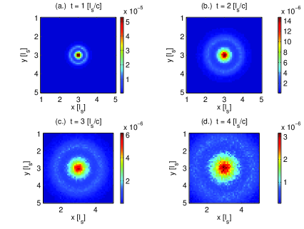
For time-resolved detection of light backscattered with the same polarization as the incident beam (co-polarized backscatter), a ring centered on the point of incidence of the beam is found to form. Initially the radius of the ring expands linearly with time. The intensity of light at the ring-peak grows weaker as the ring expands. Fig. (1) shows the intensity of the co-polarized backscattered beam for at different times. Ring formation corresponds to the red peak which noticeably expands and becomes weaker (as seen in the change in colorbar scales) as time progresses. The backscatted intensity at the ring-peak is more pronounced than backscattering at the point of incidence (the center of the plots).

Ring formation was observed in co-polarized backscattered light for all values of ranging from 0.8 to 0.97.
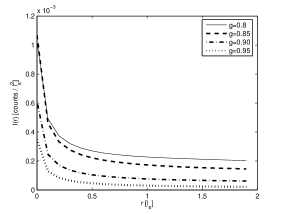
Fig. (2) shows radial profiles of the backscattered intensity with same helicity as the incident beam for = 0.8, 0.85, 0.9 and 0.95 at a single time . An important feature illustrated in Fig. (2) is the weakening of the ring-peak as increases. This is due to increased forward-peaked scattering within the medium and a resulting decrease in the likelihood of return of the photons with polarization of the incident beam.

For each value of , the ring behavior in the backscattered co-polarized light evolved in a similar way: initially the ring expanded linearly in time away from the point of incidence, growing weaker at each time step, until it reached a maximal radius at which point the ring-peak flattens and backscattering at the point of incidence begins to take over, see Fig. (3).

After sufficient time has passed the backscattered light converges to a Gaussian-like distribution with peak at the point of incidence. The maximum radius of the ring and time over which the ring is present (ring-lifetime), increases for increasing values of , prior to this flattening effect. This is a consequence of increased forward scattering as increases.
The ring behavior occurs due to successive near-forward scattering events which preserve the polarization state of the photon as a result of polarization memory effects[5],[6] described earlier. The successive near-forward scattering events give rise to arc-like trajectories of photons as they travel into the medium. Rings with smaller radii are composed of shallow penetrating photons while rings with larger radii are composed of photons that travel deeper, giving depth information about the scattering medium.
As increases, the number of near-forward scattering events needed to bring a photon back to the surface increases, giving rise to weaker ring-peaks and prolonged ring life-times. The time-dependence of the rings is a result of photons penetrating deeper into the medium as a result of forward scattering: photons that travel further into the media take longer to backscatter along the semi-circular trajectories giving rise to ring formation at later times. Fig. (4) shows a schematic depiction of this process.
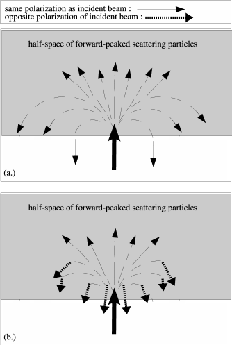
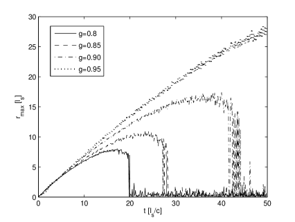
Fig. (5) shows the linear dependence on time the ring radius displays up to the point of plateauing of the ring peak. Beyond this plateauing the radial position of the peak of light intensity moves to as backscattering at the point of incidence takes over. This feature can be seen in the “fall” back to zero of each curve in Fig. (5). As well, it illustrates the relationship between anisotropy and the duration of the ring behavior of the backscattered light: the ring is prevalent for longer times as increases.
Light backscattered with the opposite helicity of the incident circularly polarized beam is found to display a different ring-like behavior for sufficiently strong forward-peaked scattering, . Light is primarily backscattered at the point of incidence, as a result of large angle scattering, with a secondary ring-peak forming some distance away from the point of incidence. As in the case of the helicity preserved backscattered light, the ring radius increases in time and the peak associated with the ring decreases simultaneously.
Fig. (6) displays the spatially resolved backscattering of light of opposite helicity with respect to the incident beam (cross-polarized backscatter) for . The dark red center of the plots correpsonds to backscattering at the point of incidence. The secondary light blue peak is the ring-peak. Light backscattered at the point of incidence results from the finite tail of the phase function, , peaked about the scattering angle . Because most of the light is transmitted as a result of forward-peaked scattering, large angle scattering is dominant when looking at the backscattered light. Large angle scattering is also responsible for the helicity flip of the backscattered light[6].
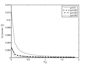
As in the case of polarization preserved backscattering, the ring observed for light bacskcsattered with opposite polarization of the incident beam moves away from the point of incidence as time progresses, growing weaker as it does so, until a plateauing occurs with eventual convergence to a Gaussian-like distribution. Fig. (7) displays the plateuing for the case in which . The inset displays the gaussian-like convergence, with peak at the point of incidence, for long times. Again, the ring behavior is attributed to successive near-forward scattering events with the presence of a small number (mostly, single) of large-angle scattering events which are responsible for the polarization flip of the backscattered light, see Fig. (4). Light that travels deeper into the medium is responsible for ring formation at later times while light that travels to smaller depths is responsible for ring formation at early times. As increases the ring-peak deminishes due to increased forward scattering resulting in greater transmittance of light, see Fig. (8).


Lastly, a comparison of rings formed by co-polarized and cross-polarized backscattered light at equal times and equal anisotropies reveals that the radial position of ring-peaks composed of light with preserved helicity are greater than the radial position of ring-peaks composed of light with flipped helicity, see Fig. (9). This is attributed to large angle scattering in which photons deviate from the successive near-forward scattering paths comprising the arc-like trajectories going back towards the incident surface. As a result, the photons that undergo large angle scattering towards the incident surface have their polarizations flipped and traverse a shorter path inside the scattering medium, resulting in a smaller ring radius, Fig. (4).

3.2 Continuous-Wave Backscattering
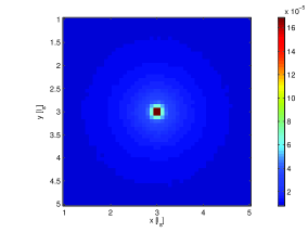
In the continuous-wave case, no ring formation is observed in the backscattered light of either preserved or flipped helicity with respect to the incident beam. Fig. (10) shows the spatially resolved continuous-wave backscattered intensity of both helicities with .

The radial profiles for and , Fig. (11), as well show no ring formation. Backscattering is dominated at the point of incidence with no ring features.
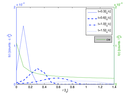
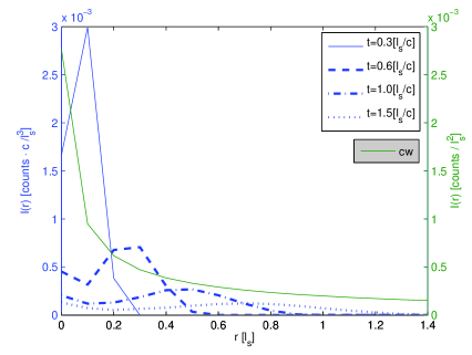
The absence of ring formation in the continuous wave backscattered light of either helicity is attributed to the smearing of the ring structure where time is integrated over all time steps. Figures 12 and 13 compare the continuous wave profiles (solid green lines) of preserved and flipped polarizations, respectively, to snap shots of the time-resolved profiles for various times. The continuous wave (time-averaged) profiles have been superimposed on the time-resolved profiles for comparison.
4 Discussion
Ring formation of backscattered light was first described by Kim and Moscoso[7] who predicted a time-independent ring formation using the scalar time-independent Fokker-Planck approximation to radiative transfer in forward scattering media. It was also postulated by these authors that the light composing the ring was of the same helicity of an incident circularly polarized beam. Ring formation was described by Kim and Moscoso as a result of successive near forward scattering events, due to the forward-peaked scattering nature of the particles, which gave rise to a steady state semi-circular trajectory of photons inside the medium. The EMC results presented here suggest partial agreement with Kim and Moscoso however, EMC differs in that it predicts a strictly time-dependent ring formation. As well, the EMC results predict ring formation for light backscattered with the same opposite helicity as that of the incident beam.
The results of the EMC simulation provide a basis for the following explanation of backscattered photon transport in forward-peaked scattering media involving time dependence. In the case of helicity preserved ring formation, the ring peak moves outward away from the point of incidence in time and grows weak simulatneously. This behavior can be understood in terms of successive near forward scattering events in which different amounts of light penetrate deeper into the medium than others, see the schematic in Fig. (4). Light that travels to shallow depths is responsible for ring formation at early times. Due to the forward-peaked nature of scattering, light that travels deeper into the medium is predominantly transmitted with only a small constituent being successively scattered to form arc-like trajectories. This light is responsible for ring formation at later times. This gives rise to an ever widening ring radius and an ever decreasing ring peak as time progresses. As well, it explains why ring peaks are smaller as increases: light is scattered about a smaller distribution of angles about the forward direction increasing the likelihood of transmittance. As well, the arc-like trajectories become longer as anisotropy increases due to the smaller deviations from the forward direction of the scattering angle resulting in longer ring lifetimes. The ring behaviors described here may be experimentally observed using time-resolved femtosecond pulses using a streak camera or Kerr gate.
In the case of helicity flipped backscattering, light is backscattered with high likelihood at the point of incidence and a secondary ring location. Backscattering at the point of incidence is attributed to the structure of the phase function of the forward-peaked scatterers. There is a finite peak in the phase function about the scattering angle giving rise to a finite probability of backscatter with helicity flip. Because photons are primarily transmitted due to the forward-peaked nature of scattering, light scattered through a large angle dominates when analyzing backscatter. Ring formation in this case is a result of forward-peaked scattering events combined with large angle scattering events. Forward-peaked scattering brings about the ring behavior while large angle scattering at some point along the photon’s trajectory is responsible for the helicity flip of the photon and the decreased ring radius, see Fig. (9). For values of , off-forward scattering remains dominant to the point of quenching opposite helicity ring formation when collecting backscattered light with arbitrary propagation direction. As a result, backscatter is dominant at the point of incidence with a Guassian-like distribution as distance from the central point of incidence increases.
The analysis of continuous-wave backscatterd light revealed an absence of ring formation. This can be reconciled with the time-dependent nature of ring formation presented above by recognizing that the time integration destroys the ring structure. It is noted that the dependence of ring formation on the collection angle of backscattered light is weak in the presence of high anisotropy, . When scattering becomes more isotropic it is expected that ring formation will first be observed when collecting light exactly backscattered anti-parallel to the incident beam. Lastly, the ring behavior can be observed when collecting light of both preserved and flipped polarizations simultaneously, Fig. (14).

5 Conclusion
The EMC method was used to investigate the backscattering of circularly polarized light at normal incidence to a half-space of forward scattering particles ranging in anisotropies of to . The spatial dependence of the backscattered intensity is examined for both the time-resolved and continuous-wave cases. Time-resolved analysis reveals ring formation for co-polarized cross-polarized backscattered light for . For values of , off-forward scattering remains dominant to the point of quenching ring formation when collecting backscattered light with arbitrary propagation direction and opposite polarization with respect to the incident beam. Ring behavior is similar in both types of backscattered light: the ring radius grows in time with the ring-peak decreasing simultaneously. The ring pattern is more pronounced when light is backscattered with the same polarization as the input. For the continuous-wave case, no such ring is observed. The ring formation presented in this study provides an important clue for understanding how light is backscattered from forward scattering media. Specifically, the EMC results suggest that photons undergo successive near-forward scattering events. Futhermore, these findings suggest that backscattered light is comprised of photons undergoing arc-like trajectories within the medium. In addition, the photons penetrate to different depths such that rings that form near the point of incidence of the pencil-like beam (at early times) are comprised of photons that have penetrated to smaller depths while rings that form further away from the point of incidence (at later times) are comprised of deeper penetrating photons. This knowledge may have potential use in polarization imaging techniques to aquire depth information of targets. Ring formation with cross-polarized backscattered light arises from succesive forward-peaked scattering events over most of the photons path with large angle scattering events taking place at some point along the trajectory to flip the photon’s helicity. It is the large angle scattering events which give rise to smaller ring radii than in the case of light backscattered with preserved polarization. It is noted that these results come in contrast to previous theoretical studies of backscattered light using the scalar time-independent Fokker-Planck approximation to radiative transfer[7] which predict a continuous-wave ring formation. The results given by the EMC method suggest that the time dependence and polarization state of the scattered light intensities play a crucial role in understanding ring formation for forward scattering media.
V. Aknowledgements
The authors thank Dr. Florain Lengyel, Assitant Director for Research Computing at the CUNY-GC computing facilities, for extensive help and support using the CUNY-GC research cluster. The authors acknowledge helpful discussions with W. Cai. This research was supported in part by ONR Award No: N00014-03-1-0463 and by NASA COSI. Kevin Phillips’ email address is kevphill@sci.ccny.cuny.edu.
References
- [1] G.D. Gilbert and J.C. Pernicka, “Improvement of underwater visibility by reduction of backscatter with a circular polarization technique,” Appl. Opt. 6, 741 (1967).
- [2] G.D. Lewis, D.L. Jordan, and P.J. Roberts, “Backscattering target detection in a turbid medium by polarization descrimination,” Appl. Opt. 38, 3937 (1999).
- [3] S.P. Morgan and M.E. Ridgway, Opt. Express 7, 395 (2000).
- [4] Xiaohui Ni and R.R. Alfano, “Time-resolved backscattering of circularly and linearly polarized light in a turbid medium,” Opt. Lett. 29, 2773 (2004).
- [5] Min Xu, R.R. Alfano, “Circular Polarization Memory of Light,” Phys. Rev. E (Submitted)
- [6] F.C. MacKintosh, J.X. Zhu, D.J. Pine, D.A. Weitz, “Polarization memory of mutliply scattered light,” Phys. Rev. B 40, 9342 (1989).
- [7] Arnold D. Kim and Miguel Moscoso, “Backscattering of beams by forward-peaked scattering media,”, Opt. Lett. 29, 74 (2004).
- [8] Min Xu, “Electic field Monte Carlo simulation of polarized light propagation in turbid media,” Opt. Express 12, 6530 (2004).
- [9] A. Ishimaru, Wave Propagation and Scattering in Random Media, I and II (Academic, New York, 1978).
- [10] S. Chandrasekhar, Radiative Transfer (Oxford University Press, Oxford, UK, 1960).
- [11] K.F. Evans and G.L. Stephens, “A new polarized atmospheric radiative transfer model,” J. Quant. Spectrosc. Radiat. Transfer 46, 413 (1991).
- [12] Arnold D. Kim and Miguel Moscoso, “Chebyshev spectral methods for radiative transfer,” SIAM J. Sci. Comput. 23, 2074 (2002).
- [13] G.W. Kattawar and G.N. Plass, “Radiance and Polarization of Multiply Scattered Light from Haze Clouds,” Appl. Opt. 7, 1519 (1968).
- [14] I. Lux and L. Koblinger, Monte Carlo Particle Transport Methods: Neutron and Photon Calculations (CRC Press, Boca Raton, Fla., 1991).
- [15] J.M Schmitt, A.H. Gandjbakhche, and R.F. Bonner, “Use of polarized light to discriminate short-path photons in a multiply scattering medium,” Appl. Opt. 31, 6535 (1992).
- [16] P. Bruscaglioni, G. Zaccanit, and Q. Wei, “Transmission of a Pulsed Polarized Light Beam Through Thick Turbid Media: Numerical Results,” Appl. Opt. 32, 6142 (1993).
- [17] M.J. Rakovic, G.W. Kattawar, M. Mehrbeolu, B.D. Cameron, L.V. Wang, S.Rastegar, and G.L. Cote, “Light backscattering polarization patterns from turbid media: theory and experiment,” Appl. Opt. 38, 3399 (1999).
- [18] S. Bartel and A.H Hielscher,“Monte Carlo Simulations of the Diffuse Backscattering Mueller Matrix for Highly Scattering Media,” Appl. Opt. 39, 1580 (2000).
- [19] Miguel Moscoso, J.B. Keller, and G. Papanicolaou, “Depolarization and blurring of optical images by biological tissue,” J. Opt. Soc. Am. A 18, 948 (2001).
- [20] H.H. Tynes, G.W. Kattawar, E.P. Zege, I.L. Katsev, A.S. Prikhach, and L.I. Chaikovskaya, “Monte Carlo and Multicomponent Approximation Methods for Vector Radiative Transfer by use of Effective Mueller Matrix Calculations ,” Appl. Opt. 40, 400 (2001).
- [21] R. Y. Rubinstein, Simulation and the Monte Carlo Method (John Wiley and Sons, 1981.)